EP0432234B1 - Procede et dispositif pour l'enduction avec des substances, p.ex. avec de la colle, pour le lavage et/ou sechage de p.ex. une bande transporteuse sans fin ou similaire - Google Patents
Procede et dispositif pour l'enduction avec des substances, p.ex. avec de la colle, pour le lavage et/ou sechage de p.ex. une bande transporteuse sans fin ou similaire Download PDFInfo
- Publication number
- EP0432234B1 EP0432234B1 EP90908155A EP90908155A EP0432234B1 EP 0432234 B1 EP0432234 B1 EP 0432234B1 EP 90908155 A EP90908155 A EP 90908155A EP 90908155 A EP90908155 A EP 90908155A EP 0432234 B1 EP0432234 B1 EP 0432234B1
- Authority
- EP
- European Patent Office
- Prior art keywords
- conveyor belt
- fabric
- fact
- working
- endless web
- Prior art date
- Legal status (The legal status is an assumption and is not a legal conclusion. Google has not performed a legal analysis and makes no representation as to the accuracy of the status listed.)
- Expired - Lifetime
Links
- 238000000034 method Methods 0.000 title claims abstract description 26
- 238000001035 drying Methods 0.000 title claims abstract description 18
- 230000008569 process Effects 0.000 title claims abstract description 17
- 238000005406 washing Methods 0.000 title claims abstract description 10
- 239000011248 coating agent Substances 0.000 title claims abstract description 7
- 238000000576 coating method Methods 0.000 title claims abstract description 7
- 239000000126 substance Substances 0.000 title claims description 9
- 239000000853 adhesive Substances 0.000 title description 11
- 230000001070 adhesive effect Effects 0.000 title description 11
- 238000004140 cleaning Methods 0.000 claims abstract description 12
- 239000000463 material Substances 0.000 claims description 12
- 238000003825 pressing Methods 0.000 claims description 8
- 239000004744 fabric Substances 0.000 claims 15
- 230000006835 compression Effects 0.000 claims 1
- 238000007906 compression Methods 0.000 claims 1
- 230000003993 interaction Effects 0.000 claims 1
- 229920001059 synthetic polymer Polymers 0.000 claims 1
- 238000007790 scraping Methods 0.000 abstract 1
- 238000007639 printing Methods 0.000 description 9
- BGPVFRJUHWVFKM-UHFFFAOYSA-N N1=C2C=CC=CC2=[N+]([O-])C1(CC1)CCC21N=C1C=CC=CC1=[N+]2[O-] Chemical compound N1=C2C=CC=CC2=[N+]([O-])C1(CC1)CCC21N=C1C=CC=CC1=[N+]2[O-] BGPVFRJUHWVFKM-UHFFFAOYSA-N 0.000 description 7
- 238000005452 bending Methods 0.000 description 6
- 238000005516 engineering process Methods 0.000 description 5
- 239000004753 textile Substances 0.000 description 4
- 238000010276 construction Methods 0.000 description 3
- 239000007788 liquid Substances 0.000 description 3
- 238000004026 adhesive bonding Methods 0.000 description 2
- 239000002313 adhesive film Substances 0.000 description 2
- 230000001680 brushing effect Effects 0.000 description 2
- 230000000694 effects Effects 0.000 description 2
- 239000000835 fiber Substances 0.000 description 2
- 230000009969 flowable effect Effects 0.000 description 2
- OKTJSMMVPCPJKN-UHFFFAOYSA-N Carbon Chemical compound [C] OKTJSMMVPCPJKN-UHFFFAOYSA-N 0.000 description 1
- 235000013358 Solanum torvum Nutrition 0.000 description 1
- 240000002072 Solanum torvum Species 0.000 description 1
- 230000009471 action Effects 0.000 description 1
- 230000008901 benefit Effects 0.000 description 1
- 229910052799 carbon Inorganic materials 0.000 description 1
- 230000001364 causal effect Effects 0.000 description 1
- 238000005520 cutting process Methods 0.000 description 1
- 238000011982 device technology Methods 0.000 description 1
- 238000007654 immersion Methods 0.000 description 1
- 239000000976 ink Substances 0.000 description 1
- 230000007257 malfunction Effects 0.000 description 1
- 238000011089 mechanical engineering Methods 0.000 description 1
- 238000010327 methods by industry Methods 0.000 description 1
- 230000000737 periodic effect Effects 0.000 description 1
- 229920000642 polymer Polymers 0.000 description 1
- 238000006748 scratching Methods 0.000 description 1
- 230000002393 scratching effect Effects 0.000 description 1
- 239000007787 solid Substances 0.000 description 1
- 239000002904 solvent Substances 0.000 description 1
- XLYOFNOQVPJJNP-UHFFFAOYSA-N water Substances O XLYOFNOQVPJJNP-UHFFFAOYSA-N 0.000 description 1
Images
Classifications
-
- B—PERFORMING OPERATIONS; TRANSPORTING
- B41—PRINTING; LINING MACHINES; TYPEWRITERS; STAMPS
- B41F—PRINTING MACHINES OR PRESSES
- B41F15/00—Screen printers
- B41F15/14—Details
- B41F15/16—Printing tables
- B41F15/18—Supports for workpieces
- B41F15/24—Supports for workpieces for webs
-
- B—PERFORMING OPERATIONS; TRANSPORTING
- B41—PRINTING; LINING MACHINES; TYPEWRITERS; STAMPS
- B41F—PRINTING MACHINES OR PRESSES
- B41F15/00—Screen printers
- B41F15/14—Details
- B41F15/40—Inking units
- B41F15/42—Inking units comprising squeegees or doctors
- B41F15/426—Inking units comprising squeegees or doctors the squeegees or doctors being magnetically attracted
-
- B—PERFORMING OPERATIONS; TRANSPORTING
- B65—CONVEYING; PACKING; STORING; HANDLING THIN OR FILAMENTARY MATERIAL
- B65G—TRANSPORT OR STORAGE DEVICES, e.g. CONVEYORS FOR LOADING OR TIPPING, SHOP CONVEYOR SYSTEMS OR PNEUMATIC TUBE CONVEYORS
- B65G45/00—Lubricating, cleaning, or clearing devices
- B65G45/10—Cleaning devices
- B65G45/12—Cleaning devices comprising scrapers
- B65G45/16—Cleaning devices comprising scrapers with scraper biasing means
Definitions
- the invention relates to a method and a device according to claims 1 and 4.
- the present invention is primarily directed to a novel treatment process which is suitable for all three functions - gluing, washing and drying the conveyor belt, and, derived therefrom, a combined or multi-stage auxiliary process in which these three work functions are connected in series in a similar process technology or run sequentially.
- this invention also encompasses the structural designs of these treatment devices according to the method.
- EP-A 311 728 A corresponding method and a device are known from EP-A 311 728.
- the invention differs from the subject matter of the aforementioned European patent application 311 728 in that at least one of the working parts or the conveyor belt is pressure-elastic and at least one of the working parts and / or the conveyor belt is flexurally elastic, wherein the pressure elasticity of the functional unit can also be brought about by that the conveyor belt is exposed in the area of the pressure of the doctor element, ie does not rest on a counter element in the opposite area and can therefore elastically deflect into the free space behind it by pressure of the doctor element on the conveyor belt.
- EP-A 311 728 shows working elements that are neither pressure nor bending elastic and as the only compensating movement can perform a pivoting movement and thus can not lead to the desired uniform operation.
- a remarkable mechanical engineering, economic and application-related advantage of this invention is the usability of an essentially identical construction or design for different purposes, which, however, in turn have a process-related, purpose-related or functional causal relationship or, in combination, form a process engineering entity.
- the endless conveyor belt e.g. A textile printing machine is usually first thinly coated with an adhesive each time it is run, then the material to be printed is laminated and printed thereon, peeled off after printing and fed to drying; the printing blanket, which is subsequently contaminated with adhesive residues, textile fibers or fluff and in some cases also with printing inks, must then be washed and then dried again after washing, in order then to be prepared for renewed adhesion.
- This procedural treatment cycle usually takes place once per each cycle and in its entirety forms part of the entire printing process, or it could also be said: it forms an auxiliary process cycle for the printing process.
- the present invention first describes a novel treatment method which is suitable for all three functions - gluing, washing and drying - of the conveyor belt, and is derived therefrom, in which these three work functions are connected in series or in sequence using the same process technology.
- this invention also encompasses the structural designs of these treatment devices according to the method.
- the working element can be referred to as a magnetically pressed doctor element, but the construction of this doctor element differs from the previously known magnetically pressed doctor elements by its identification according to the invention.
- the adhesive film is applied first, then washed and knife-coated and finally knife-dried again.
- Another possibility is to apply the adhesive film and stick on the goods, which are printed in several rounds and then removed again.
- the washing device is then actuated in repeated cycles and a repeated cycle is carried out using the drying device.
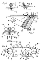
- FIGS. 3 and 4 are two exemplary embodiments of the invention and FIG. 5 schematically shows a longitudinal section through a round stencil printing machine.
- doctor blade 1 shows a known doctor blade device, in which a doctor blade 1 is arranged in a holder 2 and on a conveyor belt 3 rests. The doctor blade 1 is pressed against this conveyor belt 3 by a magnet 4.
- the disadvantage of the device shown in this figure is, for example, that the doctor blade 1 is rigid or intrinsically stiff, it has to be processed with great effort and, however, due to the inherent stiffness it always has the tendency to bend, in particular with working widths of more than 1000 mm . Since the table containing the magnet 4 or a magnetic roller usually has slight unevenness in the case of large working widths and, finally, the conveyor belt 3 can also hardly be produced with large widths and lengths without differences in thickness, the required uniformity of contact with the conveyor belt can hardly be achieved in practice. Such devices have therefore not been used in practice.
- FIG. 2 Another known embodiment is shown in FIG. Here rests on the conveyor belt 3, an elastic blade 5, which is mounted in a holder 2 and the elastic blade is pressed here via an additional magnetizable pressure strip.
- These devices according to FIG. 2 are hardly suitable due to the longitudinal and transverse elasticity of the blades 5 and their flat contact for a precise, uniform treatment that acts over the entire working width. Rather, there is more of a risk that they will smear the surface of the conveyor belt 3 and, with a steeper setting, there is also the risk of scratching and cutting.
- a magnetizable bar 7 is fastened, for example, to a swivel joint 8 and the magnetizable bar 7 consists of a Working element 9, which is made, for example, of a flexible and pressure-elastic, profiled, strip-shaped plate, preferably made of polymer plastic, and of a pressing element 11, which carries a holder 10 for inserting the working element 9.
- the holder 10 holds the working element 9 parallel to the pressing element 11, which consists of magnetizable material, and the working edge 12 protrudes slightly beyond the surface 13 of the pressing element 11 facing the magnet 4 or the conveyor belt 3.
- Fig. 3 the device according to the invention is shown in work function, the pressing element 11 and consequently also the working element 9 are tightened in an approximately perpendicular direction to the level of the conveyor belt, but so that the surface 13 of the pressing element 11 does not touch the conveyor belt, which causes a malfunction would cause.
- the working edge 12 of the working element 9 lies against the surface of the conveyor belt as a result of the magnetically induced attraction described, a bar body, which encloses the magnet 4 or is connected to it, provides the necessary counterpressure for the corresponding work function.
- any non-uniformities that may impair the function due to the counter pressure body 14 or its sliding surface or also in the conveyor belt are compensated for by the combination of the bending and pressure elasticity according to the invention with the magnetically caused contact pressure, so that an error-free application of e.g. Adhesive, or error-free cleaning or drying can be effected.
- a device 15 according to the invention is again provided below the conveyor belt 3, which carries a working element 9 in the form of a round profile rod 19 in a recess 18 on its upper part 17.
- the round profile rod 19 is secured against rotation by pinning 20. It does not necessarily have to have a circular cross section, but can have any other shape, including rounded or angular.
- the round profile bar 19 or the bar 17 carrying this is attracted by the magnet 4 and tubular bodies 16 serve as counter surfaces here.
- the process-related component of the pressure elasticity is opposed by the pressure and bending elastic conveyor belt 3 and the contact pressure direction indicated by arrow 36 of the squeegee edge creates the flexural movement clearance.
- the upper, preferably made of magnetizable material bar 17 of the device 15 according to the invention is solid, the lower, non-hatched part is cut several times over the length. As a result, the bending elasticity can be increased in an advantageous manner.
- the device according to the invention is in the working position here, ie it is raised from a latching surface 35 and in the working position by the magnetic pressure. 4, the device according to the invention is in the rest position, ie out of operation. The magnet 4 is switched off and in this state the device rests on the latching surface 35 and has no contact with the conveyor belt 3. When the magnet 4 is switched on, the device 15 is then moved in the direction of the arrow 36 until contact with the conveyor belt 3 is made.
- Both embodiments according to FIGS. 3 and 4 have in common that the strength (magnetic force) and the arrangement of the magnetic field as well as the strength (magnetizable mass) of the bar or of the second working part causing the contact pressure and also the pressure integrated in the method according to the invention. and bending elasticity components are coordinated with one another taking into account all existing or acting, mutual functional dependencies with the greatest possible care in the material selection and dimensioning of the individual components.
- FIG. 5 shows a schematic representation of a longitudinal section through a circular stencil printing machine, which is equipped with an endless conveyor belt 32, which is guided over a drive roller 27 or deflection roller 28, and in each of which one of the three possible, procedural functions of the first Application of a flowable, preferably viscous medium, such as adhesive, secondly for cleaning and thirdly for drying the conveyor belt 32, the device according to the invention is installed.
- This figure schematically shows devices 21, 22 and 23 for applying or doctoring, for example, adhesive, devices 24 and 25 for cleaning or doctoring the materials soaked with cleaning liquid, for example adhesive residues, color paste residues, textile fibers, textile fluff, and device 26 intended for drying, ie as a doctor blade.
- Fig. 5 is also shown schematically that a web 29 is placed on the conveyor belt 32, for example in the drive roller 27, together with the Conveyor belt is guided past printing stations 30 and is finally lifted off again in the area of the deflecting rollers 28.
- the cleaning devices 24, 25 can either be used either in combination or, to enhance the cleaning action, combined.
- the substance to be applied for example adhesive
- the material web is only fed to the conveyor belt and pressed against it in the area after the application of the carbon, which is not shown in FIG. 5.
- Adhesive preferably viscous, flowable substance, such as e.g. Adhesive, not to be limited to the previously described application form of coating an endless conveyor belt, but also to apply it to other coating functions, in particular applying layers to sheet-like material of all kinds, different thicknesses and different surface properties.
- rollers that release magnetic force or, conversely, magnetizable counter-pressure rollers, in which case the parts that generate the magnetic force are arranged on the side of the material web or the conveyor belt on which the application or coating or doctoring takes place.
Landscapes
- Engineering & Computer Science (AREA)
- Mechanical Engineering (AREA)
- Coating Apparatus (AREA)
- Application Of Or Painting With Fluid Materials (AREA)
- Filtering Of Dispersed Particles In Gases (AREA)
- Belt Conveyors (AREA)
Claims (14)
- Procédé pour l'enduction avec des substances, pour le lavage et/ou séchage d'une bande de transport (3, 32) ou d'une nappe de tissu (29) dans lequel on utilise pour les opérations d'application, de nettoyage et/ou de séchage respectivement une unité fonctionnelle constituée d'au moins deux parties opérationnelles (4, 9, 11, 15, 16), un élément formant racle (12, 19) fonctionnant pour étaler, glisser, racler ou écraser et un élément de contre-pression (4, 16) qui sont disposés à des faces opposées de la bande de transport (3)/de la nappe de tissu (29) et dont l'un contient le dispositif à aimant et l'autre le matériau pouvant être aimanté, caractérisé en ce qu'au moins l'une des parties opérationnelles (4, 9, 11, 15, 16) et/ou la bande de transport (3)/la nappe de tissu (29) est élastique sous pression ou que la bande de transport (3)/la nappe de tissu (29) repose à l'extérieur de la zone sur un ou plusieurs éléments de contre-pression (16) qui est opposée à la zone de contact de l'élément formant racle (19) avec la bande de transport (3)/la nappe de tissu (29) et donne ainsi à l'unité fonctionnelle une élasticité sous pression, et en ce qu'au moins l'une des parties opérationnelles (4, 9, 11, 15, 16) et/ou la bande de transport (3)/la nappe de tissu (29) est élastique en flexion et en ce que l'élément formant racle (12, 19) est pressé par le dispositif à aimant uniformément contre la bande de transport (3)/la nappe de tissu (29).
- Procédé selon la revendication 1, caractérisé en ce que l'élément formant racle (12, 19) est déplacé suivant un mouvement de va-et-vient transversalement à la direction d'avancement de la bande de transport (3)/la nappe de tissu.
- Procédé selon la revendication 1, caractérisé en ce que lors de l'application d'une substance par l'unité fonctionnelle, un dispositif formant racle est placé à la suite de celle-ci, et en ce que l'unité fonctionnelle et le dispositif formant racle traitent la bande de transport tout en se situant dans un champ magnétique.
- Dispositif pour l'enduction avec des substances, le lavage et/ou le séchage d'une bande de transport (3)/une nappe de tissu (29), dans lequel on utilise pour les opérations d'application, de nettoyage et/ou de séchage, respectivement une unité fonctionnelle qui est constituée d'au moins deux parties opérationnelles (4, 9, 11, 15, 16) disposées à des faces opposées de la bande de transport (3)/la nappe de tissu (29), d'un élément mobile formant racle (12, 19) avec un élément opérationnel (9, 19) et un élément d'application (11, 17) relié à celui-ci dans lequel est prévu un matériau pouvant être aimanté, et d'un élément de contre-pression (4, 16) qui contient un dispositif à aimant, caractérisé en ce qu'au moins l'une des parties opérationnelles (4, 9, 11, 15, 16) et/ou la bande de transport (3)/la nappe de tissu (29) est élastique sous pression ou que la bande de transport (3)/la nappe de tissu (29) repose à l'extérieur de la zone sur un ou plusieurs éléments de contre-pression (16) qui est opposée à la zone de contact de l'élément formant racle (19) avec la bande de transport (3)/la nappe de tissu (29) et donne ainsi à l'unité fonctionnelle une élasticité sous pression, et en ce qu'au moins l'une des parties opérationnelles (4, 9, 11, 15, 16) et/ou la bande de transport (3)/la nappe de tissu (29) est élastique en flexion et que l'élément formant racle (12, 19) est pressé par le dispositif à aimant uniformément contre la bande de transport (3)/la nappe de tissu (29) .
- Dispositif selon la revendication 4, caractérisé en ce que l'intensité de la force magnétique et la position du champ magnétique ainsi que la grandeur de la masse pouvant être aimantée peuvent être choisies dans la deuxième partie opérationnelle, ainsi que l'élasticité en flexion et sous pression de l'élément opérationnel (9, 19) en tenant compte des dépendances fonctionnelles mutuelles existantes ou actives.
- Dispositif selon la revendication 4 ou 5, caractérisé en ce que l'élément opérationnel (9, 19) est constitué d'une plaque élastique en flexion et sous pression, profilé, réalisé en forme de bande, de préférence en polymère
- Dispositif selon l'une des revendications 4 à 6, caractérisé en ce que l'élément d'application (11) comprenant le matériau pouvant être aimanté comprend un logement (10) pour la mise en place de l'élément de travail (9,19).
- Dispositif selon l'une des revendications 4 à 7, caractérisé en ce que l'élément opérationnel (9) présente une arête opérationnelle (12) qui fait légèrement saillie sur la face orientée vers le champ magnétique ou la bande de transport de l'élément d'application (11) et qui s'applique à l'état fonctionnel à la bande de transport (3).
- Dispositif selon l'une des revendications 4 à 8, caractérisé en ce que l'élément de travail est réalisé sous forme de tige profilée ronde (19).
- Dispositif selon la revendication 9, caractérisé en ce que la tige profilée ronde (19) a une section transversale circulaire et est assurée par des goupilles (20) contre une rotation.
- Dispositif selon l'une des revendications 4 à 10, caractérisé en ce qu'il est prévu un dispositif pour déplacer l'élément opérationnel transversalement au mouvement d'avance de la bande de transport (3).
- Dispositif selon l'une des revendications 4 à 11, caractérisé en ce que l'élément opérationnel (9, 19) est échangeable.
- Dispositif selon la revendication 4, caractérisé en ce que dans le cas de l'application de la substance par l'unité fonctionnelle (21), la substance à appliquer est d'abord appliquée avec un excédent et est raclée directement ensuite selon un dosage.
- Dispositif selon la revendication 13, caractérisé en ce que les éléments de l'unité fonctionnelle (21) sont disposés dans un champ magnétique.
Applications Claiming Priority (3)
| Application Number | Priority Date | Filing Date | Title |
|---|---|---|---|
| AT1446/89 | 1989-06-13 | ||
| AT1446/89A AT392743B (de) | 1989-06-13 | 1989-06-13 | Verfahren und einrichtung zum beschichten mit substanzen, z.b. mit klebstoff, zum waschen und/oder trocknen eines z.b. endlosen transportbandes od.dgl. |
| PCT/AT1990/000055 WO1990015716A1 (fr) | 1989-06-13 | 1990-06-06 | Procede et dispositif pour l'enduction avec des substances, p.ex. avec de la colle, pour le lavage et/ou sechage de p.ex. une bande transporteuse sans fin ou similaire |
Publications (2)
| Publication Number | Publication Date |
|---|---|
| EP0432234A1 EP0432234A1 (fr) | 1991-06-19 |
| EP0432234B1 true EP0432234B1 (fr) | 1994-12-07 |
Family
ID=3514067
Family Applications (1)
| Application Number | Title | Priority Date | Filing Date |
|---|---|---|---|
| EP90908155A Expired - Lifetime EP0432234B1 (fr) | 1989-06-13 | 1990-06-06 | Procede et dispositif pour l'enduction avec des substances, p.ex. avec de la colle, pour le lavage et/ou sechage de p.ex. une bande transporteuse sans fin ou similaire |
Country Status (6)
| Country | Link |
|---|---|
| EP (1) | EP0432234B1 (fr) |
| AT (2) | AT392743B (fr) |
| AU (1) | AU5745590A (fr) |
| BR (1) | BR9006804A (fr) |
| DE (1) | DE59007933D1 (fr) |
| WO (1) | WO1990015716A1 (fr) |
Families Citing this family (3)
| Publication number | Priority date | Publication date | Assignee | Title |
|---|---|---|---|---|
| EP0579433A1 (fr) * | 1992-07-13 | 1994-01-19 | Ichinose International Incorporated | Machine d'impression sérigraphique automatique et méthode d'impression |
| CN110104386B (zh) * | 2019-06-13 | 2024-03-26 | 烟台石川密封科技股份有限公司 | 一种汽缸垫片喷涂用不锈钢带输送机 |
| CN118654437B (zh) * | 2024-08-19 | 2024-11-05 | 山东七十二度制冷技术有限公司 | 一种食品加工速冻机 |
Citations (1)
| Publication number | Priority date | Publication date | Assignee | Title |
|---|---|---|---|---|
| EP0311742A1 (fr) * | 1987-10-10 | 1989-04-19 | Johannes Zimmer | Dispositif de raclage |
Family Cites Families (5)
| Publication number | Priority date | Publication date | Assignee | Title |
|---|---|---|---|---|
| FR687168A (fr) * | 1929-03-16 | 1930-08-05 | Dispositif d'entraînement des tissus sur les machines à imprimer en plusieurs couleurs | |
| DE1752374A1 (de) * | 1967-05-26 | 1971-05-19 | Zimmer Johannes | Rakeivorrichtung mit gleitendem Arbeitsorgan |
| CS149843B1 (fr) * | 1971-04-22 | 1973-08-23 | ||
| AT377476B (de) * | 1983-05-24 | 1985-03-25 | Zimmer Johannes | Rakelgeraet fuer flachschablonen mit zwei im abstand zueinander angeordneten rakelleisten |
| EP0311728B1 (fr) * | 1987-10-10 | 1993-03-10 | Johannes Zimmer | Dispositif de raclage |
-
1989
- 1989-06-13 AT AT1446/89A patent/AT392743B/de not_active IP Right Cessation
-
1990
- 1990-06-06 AT AT90908155T patent/ATE115041T1/de not_active IP Right Cessation
- 1990-06-06 DE DE59007933T patent/DE59007933D1/de not_active Expired - Fee Related
- 1990-06-06 AU AU57455/90A patent/AU5745590A/en not_active Abandoned
- 1990-06-06 BR BR909006804A patent/BR9006804A/pt not_active IP Right Cessation
- 1990-06-06 EP EP90908155A patent/EP0432234B1/fr not_active Expired - Lifetime
- 1990-06-06 WO PCT/AT1990/000055 patent/WO1990015716A1/fr not_active Ceased
Patent Citations (1)
| Publication number | Priority date | Publication date | Assignee | Title |
|---|---|---|---|---|
| EP0311742A1 (fr) * | 1987-10-10 | 1989-04-19 | Johannes Zimmer | Dispositif de raclage |
Also Published As
| Publication number | Publication date |
|---|---|
| AT392743B (de) | 1991-05-27 |
| ATA144689A (de) | 1990-11-15 |
| WO1990015716A1 (fr) | 1990-12-27 |
| ATE115041T1 (de) | 1994-12-15 |
| EP0432234A1 (fr) | 1991-06-19 |
| DE59007933D1 (de) | 1995-01-19 |
| AU5745590A (en) | 1991-01-08 |
| BR9006804A (pt) | 1991-08-06 |
Similar Documents
| Publication | Publication Date | Title |
|---|---|---|
| WO1989003259A1 (fr) | Dispositif activateur | |
| WO2006074921A1 (fr) | Dispositif et procede permettant d'appliquer un agent liquide sur une bande de matiere | |
| EP0432234B1 (fr) | Procede et dispositif pour l'enduction avec des substances, p.ex. avec de la colle, pour le lavage et/ou sechage de p.ex. une bande transporteuse sans fin ou similaire | |
| DE2422373A1 (de) | Verfahren und einrichtung zur herstellung von geweben mit verschiedenfarbigen schussfaeden | |
| EP0290519B1 (fr) | Dispositif pour enduire des bandes de feuilles | |
| DE6925888U (de) | Einrichtung zur herstellung einer beschichtung auf einer zum einbuegeln bestimmten stoffbahn. | |
| DE2124085A1 (fr) | ||
| WO1992003605A1 (fr) | Procede et dispositif pour deposer, appliquer par pression ou eliminer des liquides ou des substances | |
| DE3033478A1 (de) | Vorrichtung zum auftragen geringer fluessigkeitsmengen auf bahnfoermige textile flaechengebilde | |
| EP1789628B1 (fr) | Dispositif de raclage | |
| DE2637303B2 (de) | Verfahren und Vorrichtung zur Verminderung des Grauschleiers beim kontinuierlichen Färben von Textilgeweben mit Zwischentrocknung | |
| AT393973B (de) | Einrichtung zum beschichten von textilien und sonstigen flaechengebilden, bahnenfoermig oder in stuecken vorliegend | |
| DE3618935C2 (fr) | ||
| DE536644C (de) | Schlichten von Webketten | |
| CH682772A5 (de) | Beaufschlagen einer Siebdruckform mit einem Medium. | |
| DE1952009U (de) | Verklebungspresse fuer waesche- und bekleidungsstuecke mit einem endlosen zufuehrband. | |
| US5302202A (en) | Process and device for applying a coating or substance e.g. adhesive for washing and/or drying an endless conveyor belt or the like | |
| AT388118B (de) | Verfahren zum ein- oder beidseitigen beschichten bzw. impraegnieren einer warenbahn und einrichtung zur durchfuehrung des verfahrens | |
| AT349423B (de) | Streichrakelvorrichtung | |
| DE4033660A1 (de) | Verfahren und vorrichtung zur randfugenversiegelung einer isolierglaseinheit, insbesondere einer kraftfahrzeug-isolierglaseinheit | |
| DE3900672C2 (fr) | ||
| DE2243746A1 (de) | Verfahren zum aufbringen eines gleichmaessig verteilten, aus thermoplastischem oder thermohaertenden kunststoff bestehenden beschichtungsmusters auf eine stoffbahn | |
| DE1460794C (de) | Einrichtung zum vielfarbig ge musterten kontinuierlichen Einfärben von Faden, Bandern oder Bahnen | |
| EP0713771B1 (fr) | Dispositif de nettoyage pour éléments rotatifs dans des machines à imprimer | |
| AT361438B (de) | Rakelvorrichtung |
Legal Events
| Date | Code | Title | Description |
|---|---|---|---|
| PUAI | Public reference made under article 153(3) epc to a published international application that has entered the european phase |
Free format text: ORIGINAL CODE: 0009012 |
|
| 17P | Request for examination filed |
Effective date: 19910206 |
|
| AK | Designated contracting states |
Kind code of ref document: A1 Designated state(s): AT CH DE DK ES FR GB IT LI NL |
|
| 17Q | First examination report despatched |
Effective date: 19930126 |
|
| GRAA | (expected) grant |
Free format text: ORIGINAL CODE: 0009210 |
|
| AK | Designated contracting states |
Kind code of ref document: B1 Designated state(s): AT CH DE DK ES FR GB IT LI NL |
|
| PG25 | Lapsed in a contracting state [announced via postgrant information from national office to epo] |
Ref country code: GB Effective date: 19941207 Ref country code: FR Effective date: 19941207 Ref country code: ES Free format text: THE PATENT HAS BEEN ANNULLED BY A DECISION OF A NATIONAL AUTHORITY Effective date: 19941207 Ref country code: DK Effective date: 19941207 |
|
| REF | Corresponds to: |
Ref document number: 115041 Country of ref document: AT Date of ref document: 19941215 Kind code of ref document: T |
|
| REF | Corresponds to: |
Ref document number: 59007933 Country of ref document: DE Date of ref document: 19950119 |
|
| ITF | It: translation for a ep patent filed | ||
| EN | Fr: translation not filed | ||
| GBV | Gb: ep patent (uk) treated as always having been void in accordance with gb section 77(7)/1977 [no translation filed] |
Effective date: 19941207 |
|
| PLBE | No opposition filed within time limit |
Free format text: ORIGINAL CODE: 0009261 |
|
| STAA | Information on the status of an ep patent application or granted ep patent |
Free format text: STATUS: NO OPPOSITION FILED WITHIN TIME LIMIT |
|
| 26N | No opposition filed | ||
| PGFP | Annual fee paid to national office [announced via postgrant information from national office to epo] |
Ref country code: AT Payment date: 19960401 Year of fee payment: 7 |
|
| PGFP | Annual fee paid to national office [announced via postgrant information from national office to epo] |
Ref country code: DE Payment date: 19960426 Year of fee payment: 7 |
|
| PGFP | Annual fee paid to national office [announced via postgrant information from national office to epo] |
Ref country code: NL Payment date: 19960630 Year of fee payment: 7 |
|
| REG | Reference to a national code |
Ref country code: CH Ref legal event code: PL |
|
| PGFP | Annual fee paid to national office [announced via postgrant information from national office to epo] |
Ref country code: CH Payment date: 19970303 Year of fee payment: 7 |
|
| REG | Reference to a national code |
Ref country code: CH Ref legal event code: AEN Free format text: DAS PATENT IST AUFGRUND DES WEITERBEHANDLUNGSANTRAGS VOM 05.02.1997 REAKTIVIERT WORDEN. |
|
| PG25 | Lapsed in a contracting state [announced via postgrant information from national office to epo] |
Ref country code: AT Effective date: 19970606 |
|
| PG25 | Lapsed in a contracting state [announced via postgrant information from national office to epo] |
Ref country code: LI Free format text: LAPSE BECAUSE OF NON-PAYMENT OF DUE FEES Effective date: 19970630 Ref country code: CH Free format text: LAPSE BECAUSE OF NON-PAYMENT OF DUE FEES Effective date: 19970630 |
|
| PG25 | Lapsed in a contracting state [announced via postgrant information from national office to epo] |
Ref country code: NL Effective date: 19980101 |
|
| REG | Reference to a national code |
Ref country code: CH Ref legal event code: PL |
|
| NLV4 | Nl: lapsed or anulled due to non-payment of the annual fee |
Effective date: 19980101 |
|
| PG25 | Lapsed in a contracting state [announced via postgrant information from national office to epo] |
Ref country code: DE Free format text: LAPSE BECAUSE OF NON-PAYMENT OF DUE FEES Effective date: 19980303 |
|
| PG25 | Lapsed in a contracting state [announced via postgrant information from national office to epo] |
Ref country code: IT Free format text: LAPSE BECAUSE OF NON-PAYMENT OF DUE FEES;WARNING: LAPSES OF ITALIAN PATENTS WITH EFFECTIVE DATE BEFORE 2007 MAY HAVE OCCURRED AT ANY TIME BEFORE 2007. THE CORRECT EFFECTIVE DATE MAY BE DIFFERENT FROM THE ONE RECORDED. Effective date: 20050606 |