EP0432343A1 - Druckpackung - Google Patents
Druckpackung Download PDFInfo
- Publication number
- EP0432343A1 EP0432343A1 EP90104896A EP90104896A EP0432343A1 EP 0432343 A1 EP0432343 A1 EP 0432343A1 EP 90104896 A EP90104896 A EP 90104896A EP 90104896 A EP90104896 A EP 90104896A EP 0432343 A1 EP0432343 A1 EP 0432343A1
- Authority
- EP
- European Patent Office
- Prior art keywords
- pressure
- product container
- hollow cylinder
- pack according
- free space
- Prior art date
- Legal status (The legal status is an assumption and is not a legal conclusion. Google has not performed a legal analysis and makes no representation as to the accuracy of the status listed.)
- Granted
Links
Images
Classifications
-
- B—PERFORMING OPERATIONS; TRANSPORTING
- B65—CONVEYING; PACKING; STORING; HANDLING THIN OR FILAMENTARY MATERIAL
- B65D—CONTAINERS FOR STORAGE OR TRANSPORT OF ARTICLES OR MATERIALS, e.g. BAGS, BARRELS, BOTTLES, BOXES, CANS, CARTONS, CRATES, DRUMS, JARS, TANKS, HOPPERS, FORWARDING CONTAINERS; ACCESSORIES, CLOSURES, OR FITTINGS THEREFOR; PACKAGING ELEMENTS; PACKAGES
- B65D83/00—Containers or packages with special means for dispensing contents
- B65D83/14—Containers for dispensing liquid or semi-liquid contents by internal gaseous pressure, i.e. aerosol containers comprising propellant
- B65D83/60—Containers for dispensing liquid or semi-liquid contents by internal gaseous pressure, i.e. aerosol containers comprising propellant with contents and propellant separated
- B65D83/62—Containers for dispensing liquid or semi-liquid contents by internal gaseous pressure, i.e. aerosol containers comprising propellant with contents and propellant separated by membranes, bags or the like
-
- B—PERFORMING OPERATIONS; TRANSPORTING
- B65—CONVEYING; PACKING; STORING; HANDLING THIN OR FILAMENTARY MATERIAL
- B65D—CONTAINERS FOR STORAGE OR TRANSPORT OF ARTICLES OR MATERIALS, e.g. BAGS, BARRELS, BOTTLES, BOXES, CANS, CARTONS, CRATES, DRUMS, JARS, TANKS, HOPPERS, FORWARDING CONTAINERS; ACCESSORIES, CLOSURES, OR FITTINGS THEREFOR; PACKAGING ELEMENTS; PACKAGES
- B65D83/00—Containers or packages with special means for dispensing contents
- B65D83/771—Containers or packages with special means for dispensing contents for dispensing fluent contents by means of a flexible bag or a deformable membrane or diaphragm
- B65D83/7711—Containers or packages with special means for dispensing contents for dispensing fluent contents by means of a flexible bag or a deformable membrane or diaphragm the contents of a flexible bag being expelled by the contracting forces inherent in the bag or a sleeve fitting snugly around the bag
Definitions
- the invention relates to a pressure pack for spraying a liquid from an essentially pressure-free compressible product container, the product container being enclosed by a one-way stretchable, elastically prestressed hollow cylinder made of rubber-elastic material and subjected to a pressure which is dependent on the degree of filling of the product container varies between a minimum pressure P min and a maximum pressure P max and a free space is provided between the product container and the hollow cylinder.
- Such a pressure pack is known from DE-OS 31 32 906.
- the hollow cylinder used here can only be expanded in the axial direction and is provided with a base which is designed to engage in a pot-like manner in the hollow cylinder in order to fill the dead volume.
- the manufacture and assembly are accordingly complex.
- the pressure drop that occurs during the emptying of the pressure pack is very large and can result in changes in the spray formation that are intolerable. It is indeed possible to reduce the pressure drop by increasing the applied preload relative to the maximum tension of the hollow cylinder when the product container is completely empty. In this case, however, you have to accept a loss of working stroke and thus a lower degree of filling, i.e. a product quantity reduced in relation to the hollow cylinder size.
- the invention has for its object to show a pressure can be used as a spray can, which is comparatively easier to manufacture and allows higher fill levels to achieve and thereby completely spray the liquid contained in the product container with a pressure which is within the range of optimal spray formation defined by P min and P max.
- the free space between the product container and the hollow cylinder is hermetically sealed to the outside and, when the product container is emptied, is filled with a gas which has approximately the pressure P min, the liquid being fed into the product container in such an amount that the in the gas contained in the free space reaches about the pressure P max. Due to the pressure-free deformability of the product container, the pressure prevailing in the free space is transferred without loss to the liquid to be sprayed therein. When the outlet valve of the product container is actuated, the liquid is therefore always available at a pressure which is between P min and P max. In this area, the liquid can be sprayed in an optimal manner. There is therefore no risk of undesired droplet formation at the outlet nozzle of the spray valve, either when the product container is completely full or when it is empty.
- the dead space of the hollow cylinder in the pressure pack according to the invention is completely filled with a pressure gas cushion.
- the elastic properties of the hollow cylinder are hereby supplemented in an advantageous manner.
- the gas obtained in the pressure gas cushion suitably consists of argon or air. This makes special measures to achieve good environmental compatibility unnecessary.
- the free space containing the prestressed gas is either filled with a diffusion-proof gas, for example with argon, or is separated from the surroundings by a gas-tight diffusion barrier.
- a diffusion-proof gas for example with argon
- This can be a coating made of a deformable material on the inside and / or outside of the hollow cylinder, for example one of the known sealing materials that are used in the tire industry.
- a planter as a diffusion barrier, which surrounds the outside of the hollow cylinder.
- the planter expediently consists of a metallic material and can at the same time serve to mark the contents or as an advertising medium.
- the pressure P 10 should be such that the atmospheric pressure is at least reached when the product container is completely empty. Diffusion losses from the free space (3) can be reduced to a certain extent by the planter compensate since a pressure drop in the free space 3 is opposed by a pressure increase in the intermediate space 10. If the excess pressure occurring in the intermediate space 10 when filling the product container 1 or the free space 3 is undesirable, a valve provided in the wall of the planter can be actuated and the compressed air can be discharged. The valve then closes automatically, so that gas which diffuses from the free space 3 into the intermediate space 10 during storage leads there to the compensatory pressure increase. Before, on the other hand, a negative pressure can arise in the intermediate space 10 during rapid emptying, a compensation with the atmosphere occurs by automatically opening the valve.
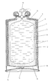
- This shows a pressure pack in a longitudinal section, which is intended for spraying a liquid 4 from a product container 1 which can be compressed essentially without pressure.
- the product container 1 is enclosed by a longitudinally stretchable, elastically prestressed hollow cylinder 2 made of rubber-elastic material, which is fastened to floors 6 in the region of its front ends. These consist of deep-drawn, metallic molded parts, the upper part of which is used for fixing in a metallic planter 5.
- the hollow cylinder 2 is reinforced in the area of its outside by a vertical spacing from one another, which is not expandable under normal operating conditions, metallic rings 7 and is coated with an elastically stretchable coating made of butyl rubber, which serves as a diffusion barrier 8. This is deformable together with the hollow cylinder 2.
- the free space 3 between the product container 1 and the hollow cylinder 2 is filled with air.
- P min which, when the spray valve 9 is actuated, still permits optimal spraying of the liquid 4 contained in the product container 1 during normal use.
- the pressure required in this regard depends on the type of liquid 4 to be sprayed. It can be determined using simple tests.
- the hollow cylinder 2 is enclosed on the outside by a planter 5 and connected to it in the region of the upper base.
- the planter 5 is made of metallic material and is therefore both impermeable to diffusion and pressure-resistant.
- the intermediate space 10 formed in this way is filled with air, which has the pressure P 10 when the product container is empty, which is at least as big as the pressure of the atmosphere.
- the pressure of the gas contained in the intermediate space 10 is significantly higher.
- the spring elasticity of the hollow cylinder 2 is thereby noticeably supported.
- the excess pressure of the gas inside the hollow cylinder 2 guarantees a complete emptying of the product container 1 at the intended excess pressure P min.
- Both the hollow cylinder 2, which can be deformed in one direction by means of reinforcement, and the product container 1 can have a different shape within the scope of the invention, as can the shape of the pressure pack as a whole.
- openings with valve function can be provided for adjusting the gas pressure in the free space 3 and also in the intermediate space 10.
- the pressure vessel according to the invention can also be used for pasty products.
- the achievable high degree of filling with a particularly low pressure difference between P max and P min is also an advantage and helps to ensure that the sprayed product line is very uniform.
Landscapes
- Engineering & Computer Science (AREA)
- Mechanical Engineering (AREA)
- Chemical & Material Sciences (AREA)
- Dispersion Chemistry (AREA)
- Containers And Packaging Bodies Having A Special Means To Remove Contents (AREA)
- Nozzles (AREA)
- Jellies, Jams, And Syrups (AREA)
- Pharmaceuticals Containing Other Organic And Inorganic Compounds (AREA)
Abstract
Description
- Die Erfindung betrifft eine Druckpackung zum Versprühen einer Flüssigkeit aus einem im wesentlichen drucklos zusammendrückbaren Produktbehälter, wobei der Produktbehälter von einem nur in einer Richtung dehnbaren, elastisch vorgespannten Hohlzylinder aus gummielastischem Werkstoff umschlossen und mit einem Druck beaufschlagt ist, der in Abhängigkeit von dem Füllungsgrad des Produktbehälters varriert zwischen einem Mindestdruck P min und einem Höchstdruck P max und wobei zwischen dem Produktbehälter und dem Hohlzylinder ein Freiraum vorgesehen ist.
- Eine solche Druckpackung ist aus der DE-OS 31 32 906 bekannt. Der dabei zur Anwendung gelangende Hohlzylinder ist nur in axialer Richtung dehnbar und mit einem Boden versehen, der zur Ausfüllung des Totvolumens topfartig in den Hohlzylinder eingreifend gestaltet ist. Die Herstellung und Montage sind dementsprechend aufwendig. Der sich während der Entleerung der Druckpackung ergebende Druckabfall ist jedoch sehr groß und kann eine Änderungen der Sprühnebelbildung zur Folge haben, die nicht tolerierbar ist. Es ist zwar möglich, den Druckabfall zu vermindern, in dem man die angewendete Vorspannung bei vollständig entleertem Produktbehälter relativ zur Maximalspannung des Hohlzylinders erhöht wird. In diesem Falle muß man aber einen Verlust an Arbeitshub und somit einen geringeren Füllgrad in Kauf nehmen, d.h. eine im Verhältnis zur Hohlzylindergröße reduzierte Produktmenge.
- Der Erfindung liegt die Aufgabe zugrunde, eine als Sprühdose verwendbare Druckpackung zu zeigen, die sich vergleichsweise einfacher herstellen läßt und es gestattet, höhere Füllgrade zu erreichen und dabei die in dem Produktbehälter enthaltene Flüssigkeit restlos zu versprühen mit einem Druck, der innerhalb des durch P min und P max umgrenzten Bereiches optimaler Sprühnebelbildung liegt.
- Diese Aufgabe wird erfindungsgemäß mit den kennzeichnenden Merkmalen von Anspruch 1 gelöst. Auf vorteilhafte Ausgestaltungen nehmen die Unteransprüche Bezug.
- Bei der erfindungsgemäßen Druckpackung ist der Freiraum zwischen dem Produktbehälter und dem Hohlzylinder hermetisch nach außen abgeschlossen und bei entleertem Produktbehälter mit einem Gas gefüllt, das etwa den Druck P min aufweist, wobei die Flüssigkeit in einer solchen Menge in den Produktbehälter eingespeist ist, daß das in dem Freiraum enthaltene Gas etwa den Druck P max erreicht. Durch die drucklose Verformbarkeit des Produktbehälters wird der in dem Freiraum herrschende Druck verlustfrei auf die in diesem enthaltene, zu versprühende Flüssigkeit übertragen. Bei einer Betätigung des Auslaßventils des Produktbehälters ist die Flüssigkeit daher stets mit einem Druck verfügbar, der zwischen P min und P max liegt. In diesem Bereich ist die Flüssigkeit in optimaler Weiser versprühbar. Weder bei völlig gefüllten Produktbehälter noch beim Erreichen des Entleerungszustandes ist daher eine unerwünschte Tropfenbildung an der Austrittsdüse des Sprühventils zu befürchten.
- Der Totraum des Hohlzylinders ist bei der erfindungsgemäßen Druckpackung vollständig mit einem Druckgaspolster ausgefüllt. Die elastischen Eigenschaften des Hohlzylinders werden hierdurch in einer vorteilhaften Weise ergänzt.
- Das in dem Druckgaspolster erhaltene Gas besteht zweckmäßig aus Argon oder Luft. Besondere Maßnahmen zur Erzielung einer guten Umweltverträglichkeit sind hierdurch entbehrlich.
- Um bei einer langen Zwischenlagerung der Druckpackung eine gute Funktionssicherheit zu gewährleisten, hat es sich als vorteilhaft bewährt, wenn der das vorgespannte Gas enthaltende Freiraum entweder mit einem diffusionssicheren Gas gefüllt ist, beispielsweise mit Argon, oder durch eine gasdichte Diffusionssperre von der Umgebung abgetrennt ist. Hierbei kann es sich um eine innen und/oder außenseitig an dem Hohlzylinder angebrachten Beschichtung aus einem verformbaren Werkstoff handeln, beispielsweise aus einem der bekannten Dichtwerkstoffe, die in der Reifenindustrie gebräuchlich sind. Daneben besteht auch die Möglichkeit, als Diffusionssperre einen Übertopf zu verwenden, der den Hohlzylinder außenseitig umschließt. Zweckmäßigerweise besteht der Übertopf aus einem metallischen Werkstoff und kann gleichzeitig der Kennzeichnung des Inhaltes bzw. als Werbeträger dienen.
- Falls als Diffussionsperre ein Übertopf zur Anwendung gelangt, besteht die Möglichkeit, den durch den Abstand zwischen dem Übertopf und dem Hohlzylinder gebildeten Zwischenraum mit Luft zu füllen. Hierbei bietet es sich an, die Luft mit dem Druck P 10 elastisch vorzuspannen, um eine Unterstützung der Federelastizität des Hohlzylinders zu erreichen.
- Jedenfalls sollte der Druck P 10 so bemessen sein, daß bei völlig entleertem Produktbehälter der atmosphärische Druck zumindest erreicht wird. Diffusionsverluste aus dem Freiraum (3) lassen sich durch den Übertopf zu einem gewissen Anteil kompensieren, da einem Druckabfall im Freiraum 3 ein Druckanstieg im Zwischenraum 10 gegenübersteht. Ist der beim Befüllen des Produktbehälters 1 bzw. des Freiraumes 3 im Zwischenraum 10 entstehende Überdruck unerwünscht, so kann ein in der Wand des Übertopfes vorgesehenes Ventil betätigt und die komprimierte Luft abgelassen werden. Danach schließt sich das Ventil selbsttätig, so daß bei der Lagerung eventuell vom Freiraum 3 in den Zwischenraum 10 diffundierendes Gas dort zu dem kompensatorischen Druckanstieg führt. Bevor andererseits bei rascher Entleerung ein Unterdruck im Zwischenraum 10 entstehen kann tritt durch selbsttätiges Öffnen des Ventils ein Ausgleich mit der Atmosphäre ein.
- Der Gegenstand der Erfindung wird nachfolgend anhand der in der Anlage beigefügten Zeichnung weiter verdeutlicht. Diese zeigt eine Druckpackung in längsgeschnittener Darstellung, welche zum Versprühen einer Flüssigkeit 4 aus einem im wesentlichen drucklos zusammendrückbaren Produktbehälter 1 bestimmt ist. Der Produktbehälter 1 ist von einem nur in Längsrichtung dehnbaren, elastisch vorgespannten Hohlzylinder 2 aus gummielastischem Werkstoff umschlossen, der im Bereich seiner stirnseitigen Enden an Böden 6 befestigt ist. Diese bestehen aus tiefgezogenen, metallischen Formteilen, von denen das Obere der Festlegung in einem metallischen Übertopf 5 dient. Der Hohlzylinder 2 ist im Bereich seiner Außenseite durch einen senkrechten Abstand voneinander aufweisende, unter normalen Betriebsbedingungen nicht dehnbare, metallische Ringe 7 armiert und mit einer elastisch dehnbaren Beschichtung aus Butylkautschuk überzogen, welche als Diffusionssperre 8 dient. Diese ist gemeinsam mit dem Hohlzylinder 2 verformbar.
- Der Freiraum 3 zwischen dem Produktbehälter 1 und dem Hohlzylinder 2 ist mit Luft gefüllt. Diese ist bei entleertem Produktbehälter 1 vorgespannt auf einen Druck P min, der bei einer Betätigung des Sprühventils 9 noch ein optimales Versprühen der während der normalen Verwendung in dem Produktbehälter 1 enthaltenen Flüssigkeit 4 gestattet. Der diesbezüglich benötigte Druck ist abhängig von der Art der zu versprühenden Flüssigkeit 4. Er läßt sich anhand einfacher Versuche bestimmen.
- Zur Herstellung der Betriebsbereitschaft wird in den Produktbehälter der im Sinne der vorstehenden Darlegungen vorbereiteten Druckpackung soviel zu versprühende Flüssigkeit eingespeist, daß die in dem Freiraum 3 enthaltene Luft den Druck P max erreicht, bei dem das optimale Sprühbild erreicht wird. Der bei P min vorgespannte Hohlzylinder nimmt seine vorgesehene Maximaldehnung ein, wenn der Druck P max erreicht ist. Auch der diesbezügliche Wert ist von der Art der zu versprühenden Flüssigkeit 4 und der verwendeten Düse abhängig und läßt sich gegebenenfalls anhand einfacher Versuche ermitteln.
- Der Hohlzylinder 2 ist bei dem gezeigten Ausführungsbeispiel außenseitig von einem Übertopf 5 umschlossen und im Bereich des oberen Bodens mit diesem verbunden. Der Übertopf 5 besteht aus metallischem Werkstoff und ist hierdurch sowohl diffusionsundurchlässig als auch druckfest. Er weist in dem gezeigten, bis zur Obergrenze aufgefüllten Zustand des Produktbehälters 1 noch einen allseitigen Abstand von dem Hohlzylinder 2 auf sowie von dessen unterem Boden 6. Der hierdurch gebildete Zwischenraum 10 ist mit Luft gefüllt, welche bei entleertem Produktbehälter den Druck P 10 aufweist, welcher wenigstens so groß ist wie der Druck der Atmosphäre. In dem gezeigten, vollständig gefüllten Zustand des Produktbehälters 1 ist der Druck des in dem Zwischenraum 10 enthaltenen Gases wesentlich höher. Die Federelastitziät des Hohlzylinders 2 wird hierdurch merklich unterstützt. Zusätzlich ergibt sich eine gewisse Reduzierung von diffusionsbedingten Druckverlusten des Freiraumes 3, welche sich bei längerer Lagerung auftreten können.
- Der im Innern des Hohlzylinders 2 herrschende Überdruck des Gases garantiert eine vollständige Entleerung des Produktbehälters 1 bei dem vorgesehenen Überdruck P min. Sowohl der vermittels einer Armierung nur in einer Richtung verformbare Hohlzylinder 2 als auch der Produktbehälter 1 können im Rahmen der Erfindung eine andere Gestalt erhalten, desgleichen die Form der Druckpackung insgesamt. Ferner können zur Einstellung des Gasdruckes im Freiraum 3 und ebenso im Zwischenraum 10 nicht dargestellte Öffnungen mit Ventilfunktion vorgesehen werden.
- Der erfindungsgemäße Druckbehälter kann auch für pastöse Produkte Verwendung finden. Der erreichbare hohe Füllgrad bei zugleich besonders geringem Druckunterschied zwischen P max und P min ist dabei ebenfalls von Vorteil und verhilft zu großer Gleichmäßigkeit des ausgespritzten Produktstranges.
Claims (10)
- Druckpackung zum Versprühen einer Flüssigkeit aus einem im wesentlichen drucklos zusammendrückbaren Produktbehälter wobei der Produktbehälter von einem nur in einer Richtung dehnbaren, elastisch vorgespannten Hohlzylinder aus gummielastischem Werkstoff umschlossen und mit einem Druck beaufschlagt ist, der in Abhängigkeit von dem Füllgrad des Produktbehälters variiert zwischen einem Mindestdruck P min und einem Höchstdruck P max, und wobei zwischen dem Produktbehälter und dem Hohlzylinder ein Freiraum vorgesehen ist, dadurch gekennzeichnet, daß der Freiraum (3) nach außen hermetisch abgeschlossen und bei entleertem Produktbehälter (1) mit einem Gas gefüllt ist, das etwa den Druck P min aufweist und daß die Flüssigkeit (4) in einer solchen Menge in den Produktbehälter (1) eingespeist ist, daß das in dem Freiraum (3) enthaltene Gas etwa den Druck P max erreicht.
- Druckpackung nach Anspruch 1, dadurch gekennzeichnet, daß das Gas aus Argon besteht.
- Druckpackung nach Anspruch 1, dadurch gekennzeichnet, daß das Gas aus Luft besteht.
- Druckpackung nach Anspruch 1 bis 3, dadurch gekennzeichnet, daß der Freiraum (3) durch eine gasdichte Diffusionssperre (5, 8) von der Umgebung abgetrennt ist.
- Druckpackung nach Anspruch 4, dadurch gekennzeichnet, daß die Diffusionssperre aus einer an dem Hohlzylinder (2) angebrachten Beschichtung (8) aus verformbarem Werkstoff besteht.
- Druckpackung nach Anspruch 4, dadurch gekennzeichnet, daß die Diffusionssperre aus einem den Hohlzylinder (2) umschließenden Übertopf (5) besteht.
- Druckpackung nach Anspruch 6, dadurch gekennzeichnet, daß der Übertopf (5) aus einem metallischen Werkstoff besteht.
- Druckpackung nach Anspruch 6 bis 7, dadurch gekennzeichnet, daß der Übertopf (5) den Hohlzylinder (2) in einem Abstand umschließt und daß der durch den Abstand gebildete Zwischenraum (10) mit Luft gefüllt ist.
- Druckpackung nach Anspruch 8, dadurch gekennzeichnet, daß die in dem Zwischenraum (10) enthaltene Luft bei entleertem Produktbehälter (1) den Druck P 10 aufweist und daß der Druck P 10 wenigstens so groß ist wie der atmosphärische Druck.
- Druckpackung nach Anspruch 8, dadurch gekennzeichnet, daß die Wandung des Übertopfes (5) eine Öffnung (11) aufweist, in der ein nach innen durchlässiges Rückschlagventil angeordnet ist und daß das Rückschlagventil von außen betätigbar ist.
Priority Applications (1)
| Application Number | Priority Date | Filing Date | Title |
|---|---|---|---|
| AT90104896T ATE101835T1 (de) | 1989-12-08 | 1990-03-15 | Druckpackung. |
Applications Claiming Priority (2)
| Application Number | Priority Date | Filing Date | Title |
|---|---|---|---|
| DE3940601 | 1989-12-08 | ||
| DE3940601 | 1989-12-08 |
Publications (2)
| Publication Number | Publication Date |
|---|---|
| EP0432343A1 true EP0432343A1 (de) | 1991-06-19 |
| EP0432343B1 EP0432343B1 (de) | 1994-02-23 |
Family
ID=6395072
Family Applications (1)
| Application Number | Title | Priority Date | Filing Date |
|---|---|---|---|
| EP19900104896 Expired - Lifetime EP0432343B1 (de) | 1989-12-08 | 1990-03-15 | Druckpackung |
Country Status (6)
| Country | Link |
|---|---|
| US (1) | US5069363A (de) |
| EP (1) | EP0432343B1 (de) |
| JP (1) | JPH03187874A (de) |
| AT (1) | ATE101835T1 (de) |
| BR (1) | BR9003212A (de) |
| DE (1) | DE59004681D1 (de) |
Cited By (5)
| Publication number | Priority date | Publication date | Assignee | Title |
|---|---|---|---|---|
| FR2703980A1 (fr) * | 1993-04-13 | 1994-10-21 | Helispire Sarl | Dispositif pour diffuser ou pulvériser de faibles quantités de fluide. |
| DE4333627C2 (de) * | 1993-10-04 | 2000-09-07 | Kertels Peter | Verpackung als Dispenser für ein unter Druck stehendes, fluidförmiges Füllgut |
| WO2009032771A3 (en) * | 2007-08-28 | 2009-05-14 | Entegris Inc | Method and appararus for dispensing fluids |
| DE202017002628U1 (de) | 2017-05-16 | 2018-08-17 | Claude Valerius | In seiner Form veränderbares flexibles Behältnis |
| US11008739B1 (en) * | 2020-02-11 | 2021-05-18 | Lvm Technology, Llc | Vapor-liquid mixture-based constant pressure hydropneumatics system |
Families Citing this family (22)
| Publication number | Priority date | Publication date | Assignee | Title |
|---|---|---|---|---|
| US5535951A (en) * | 1989-07-06 | 1996-07-16 | Utter; Steven | Misting apparatus |
| US5622056A (en) * | 1992-08-07 | 1997-04-22 | Utter; Steven | Misting apparatus |
| JPH10511887A (ja) * | 1994-10-18 | 1998-11-17 | スティーヴン エム アッター | ポータブルミスト冷却装置 |
| US5915595A (en) * | 1996-08-21 | 1999-06-29 | U.S. Can Company | Aerosol dispensing container and method for assembling same |
| US5797520A (en) * | 1996-09-24 | 1998-08-25 | Northrop Grumman Corporation | Metering system and method for use with fluids having a high solid content |
| WO1999016684A1 (fr) | 1997-10-01 | 1999-04-08 | Osaka Shipbuilding Co., Ltd. | Contenant sous pression double conçu pour charger une sous-cupule et produits sous pression doubles utilisant ce contenant |
| US6389835B1 (en) | 1999-06-02 | 2002-05-21 | Joel S. Uranga | Misting system for vehicles |
| US6481642B1 (en) | 2000-08-28 | 2002-11-19 | Ralph Frank Louis, Jr. | Portable misting apparatus and method for delivering a mist |
| US6439430B1 (en) | 2000-09-22 | 2002-08-27 | Summit Packaging Systems, Inc. | Collapsible bag, aerosol container incorporating same and method of assembling aerosol container |
| DE10251306A1 (de) * | 2002-11-04 | 2004-05-19 | Hilti Ag | Druckbehälter |
| US20040251272A1 (en) * | 2003-06-13 | 2004-12-16 | Haywood Hunter | Sunless tanning spray dispenser |
| US20080257883A1 (en) | 2007-04-19 | 2008-10-23 | Inbev S.A. | Integrally blow-moulded bag-in-container having an inner layer and the outer layer made of the same material and preform for making it |
| US20080258356A1 (en) | 2007-04-19 | 2008-10-23 | Inbev S.A. | Integrally blow-moulded bag-in-container comprising an inner layer and an outer layer comprising energy absorbing additives, and preform for making it |
| US20150266231A1 (en) | 2007-04-19 | 2015-09-24 | Anheuser-Busch Inbev S.A. | Integrally blow-moulded bag-in-container having a bag anchoring point; process for the production thereof; and tool thereof |
| US9919841B2 (en) | 2007-04-19 | 2018-03-20 | Anheuser-Busch Inbev S.A. | Integrally blow-moulded bag-in-container having interface vents opening to the atmosphere at location adjacent to bag's mouth, preform for making it; and processes for producing the preform and bag-in-container |
| AU2009201024B2 (en) * | 2008-03-14 | 2013-10-24 | Bissell Inc. | Manual spray cleaner |
| DE102010038912A1 (de) * | 2010-08-04 | 2012-02-09 | Huhtamaki Ronsberg Zn Der Huhtamaki Deutschland Gmbh & Co. Kg | Bag-on-Valve-System mit einem Füllgut-Behälter für aggressive Füllgüter, Füllgut-Behälter für ein Bag-on-Valve-System, Folienlaminat zur Herstellung eines Füllgut-Behälters und Verwendung des Folienlaminats für ein Bag-on-Valve-System |
| JP2015000748A (ja) * | 2013-06-17 | 2015-01-05 | 信越ポリマー株式会社 | 噴射容器 |
| US20150239584A1 (en) * | 2014-02-26 | 2015-08-27 | Elc Management Llc | Aerosol Package With Fermentation Propulsion |
| US20150239647A1 (en) * | 2014-02-26 | 2015-08-27 | Elc Management Llc | Aerosol Package With Fermentation Propulsion |
| WO2015200311A1 (en) * | 2014-06-23 | 2015-12-30 | Timms Broadus | Manual squeeze bottle applicator for atomizing liquids |
| US20220096687A1 (en) * | 2020-09-29 | 2022-03-31 | Tabitha Angel Bryant | Sanitizer Aerosol Dispensing Apparatus |
Citations (4)
| Publication number | Priority date | Publication date | Assignee | Title |
|---|---|---|---|---|
| US3974945A (en) * | 1975-01-27 | 1976-08-17 | Norman D. Burger | Aerosol dispensing system |
| US4077543A (en) * | 1977-02-18 | 1978-03-07 | Continental Can Company, Inc. | Propellantless aerosol container |
| US4121737A (en) * | 1975-11-24 | 1978-10-24 | Kain's Research and Development Co., Inc. | Apparatus for pressure dispensing of fluids |
| EP0069699A1 (de) * | 1981-05-20 | 1983-01-12 | Winfried Jean Werding | Behälter zur Ausgabe von flüssigen oder cremigen Produkten mit einer Vorrichtung zur Verminderung der Ausgabeverluste |
Family Cites Families (6)
| Publication number | Priority date | Publication date | Assignee | Title |
|---|---|---|---|---|
| US3240394A (en) * | 1959-08-26 | 1966-03-15 | Modern Lab Inc | Pressurized dispensing container |
| GB1327800A (en) * | 1970-08-28 | 1973-08-22 | Idees Soc Civ | Pressurized measuring dispenser |
| US3828977A (en) * | 1972-06-14 | 1974-08-13 | Continental Can Co | Compartment bag assembly for dispensing containers |
| JPS5190680A (de) * | 1975-02-04 | 1976-08-09 | ||
| DE3132906A1 (de) * | 1980-03-28 | 1983-03-03 | Berthold H. Dr. 5630 Remscheid Daimler | Verfahren und vorrichtung zur speicherung von fliessfaehigen stoffen zwecks druckfoerderung, insbesondere spraydosen, spritzgeraete und dosiervorrichtungen |
| US4458830A (en) * | 1981-05-18 | 1984-07-10 | Werding Winfried J | Appliance for discharging a non-compressible liquid, creamy or pasty product under pressure |
-
1990
- 1990-03-15 AT AT90104896T patent/ATE101835T1/de not_active IP Right Cessation
- 1990-03-15 DE DE90104896T patent/DE59004681D1/de not_active Expired - Fee Related
- 1990-03-15 EP EP19900104896 patent/EP0432343B1/de not_active Expired - Lifetime
- 1990-03-21 US US07/496,903 patent/US5069363A/en not_active Expired - Fee Related
- 1990-07-06 BR BR909003212A patent/BR9003212A/pt unknown
- 1990-09-10 JP JP2239770A patent/JPH03187874A/ja active Pending
Patent Citations (4)
| Publication number | Priority date | Publication date | Assignee | Title |
|---|---|---|---|---|
| US3974945A (en) * | 1975-01-27 | 1976-08-17 | Norman D. Burger | Aerosol dispensing system |
| US4121737A (en) * | 1975-11-24 | 1978-10-24 | Kain's Research and Development Co., Inc. | Apparatus for pressure dispensing of fluids |
| US4077543A (en) * | 1977-02-18 | 1978-03-07 | Continental Can Company, Inc. | Propellantless aerosol container |
| EP0069699A1 (de) * | 1981-05-20 | 1983-01-12 | Winfried Jean Werding | Behälter zur Ausgabe von flüssigen oder cremigen Produkten mit einer Vorrichtung zur Verminderung der Ausgabeverluste |
Cited By (8)
| Publication number | Priority date | Publication date | Assignee | Title |
|---|---|---|---|---|
| FR2703980A1 (fr) * | 1993-04-13 | 1994-10-21 | Helispire Sarl | Dispositif pour diffuser ou pulvériser de faibles quantités de fluide. |
| DE4333627C2 (de) * | 1993-10-04 | 2000-09-07 | Kertels Peter | Verpackung als Dispenser für ein unter Druck stehendes, fluidförmiges Füllgut |
| WO2009032771A3 (en) * | 2007-08-28 | 2009-05-14 | Entegris Inc | Method and appararus for dispensing fluids |
| CN101970311B (zh) * | 2007-08-28 | 2014-05-21 | 安堤格里斯公司 | 施配流体之装置及方法 |
| US8844774B2 (en) | 2007-08-28 | 2014-09-30 | Entegris, Inc. | Pressurized system for dispensing fluids |
| US9556012B2 (en) | 2007-08-28 | 2017-01-31 | Entegris, Inc. | Pressurized system for dispensing fluids |
| DE202017002628U1 (de) | 2017-05-16 | 2018-08-17 | Claude Valerius | In seiner Form veränderbares flexibles Behältnis |
| US11008739B1 (en) * | 2020-02-11 | 2021-05-18 | Lvm Technology, Llc | Vapor-liquid mixture-based constant pressure hydropneumatics system |
Also Published As
| Publication number | Publication date |
|---|---|
| DE59004681D1 (de) | 1994-03-31 |
| BR9003212A (pt) | 1991-08-27 |
| JPH03187874A (ja) | 1991-08-15 |
| ATE101835T1 (de) | 1994-03-15 |
| US5069363A (en) | 1991-12-03 |
| EP0432343B1 (de) | 1994-02-23 |
Similar Documents
| Publication | Publication Date | Title |
|---|---|---|
| EP0432343B1 (de) | Druckpackung | |
| DE69009754T2 (de) | Dosierventil für aerosolbehälter. | |
| DE69223314T2 (de) | Druckgas-aerosolsystem mit einem dampfeinlass versehenen steigrohr | |
| DE69108174T2 (de) | Ausgabeventil für einen Behälter mit einer unter einem Druck eines Gases stehenden Flüssigkeit und mit einem derartigen Ventil versehener Behälter. | |
| DE2749219A1 (de) | Dosierventil | |
| DE7530421U (de) | Handbetaetigter miniaturzerstaeuber | |
| WO1991019653A1 (de) | Behältnis aus flexiblem kunststoff zur befestigung an einer starren haftfläche und verfahren zur befestigung des behältnisses an einer starren haftfläche | |
| DE3503354A1 (de) | Wirkstoff-spender | |
| WO1990010583A1 (de) | Zweikammerpackung | |
| DE2409409A1 (de) | Insassensicherheitseinrichtung fuer fahrzeuge | |
| EP0057226A1 (de) | Schubregler zur verwendung im innern von unter gasdruck stehenden behältern. | |
| DE1184104B (de) | Verfahren und Vorrichtung zur Ausgabe einer vorbestimmten Menge einer Fluessigkeit aus einem Behaelter | |
| DE1199643B (de) | Behaelter mit einem von Hand zu betaetigenden Abgabeventil | |
| EP0024659A1 (de) | Zweikammerpackung | |
| DE2442328A1 (de) | Vorrichtung zum abgeben eines fludes unter druck | |
| DE8715785U1 (de) | Ventil | |
| DE3210777C2 (de) | ||
| DE2737326A1 (de) | Ventilanordnung fuer aerosolbehaelter | |
| DE2832640A1 (de) | Hydraulischer stossdaempfer | |
| EP0417440A1 (de) | Druckmittelspeicher, insbesondere für Fahrzeug-Bremsanlagen | |
| DE1475158A1 (de) | Spruehventil fuer Aerosole | |
| CH591901A5 (en) | Fluid dispenser - having expansible elastomeric bladder | |
| DE2159391A1 (de) | Federvorrichtung zum Abfangen und Dämpfen von stoßartigen Belastungen | |
| DE1425727B2 (de) | Füll- und Entnahmeventil für Aerosolbehälter | |
| EP0145908A1 (de) | Behälter für versprühbare Medien mit Kolbenpumpe |
Legal Events
| Date | Code | Title | Description |
|---|---|---|---|
| PUAI | Public reference made under article 153(3) epc to a published international application that has entered the european phase |
Free format text: ORIGINAL CODE: 0009012 |
|
| 17P | Request for examination filed |
Effective date: 19910311 |
|
| AK | Designated contracting states |
Kind code of ref document: A1 Designated state(s): AT BE CH DE DK ES FR GB GR IT LI LU NL SE |
|
| 17Q | First examination report despatched |
Effective date: 19920907 |
|
| GRAA | (expected) grant |
Free format text: ORIGINAL CODE: 0009210 |
|
| AK | Designated contracting states |
Kind code of ref document: B1 Designated state(s): AT BE CH DE DK ES FR GB GR IT LI LU NL SE |
|
| PG25 | Lapsed in a contracting state [announced via postgrant information from national office to epo] |
Ref country code: IT Free format text: LAPSE BECAUSE OF FAILURE TO SUBMIT A TRANSLATION OF THE DESCRIPTION OR TO PAY THE FEE WITHIN THE PRE;WARNING: LAPSES OF ITALIAN PATENTS WITH EFFECTIVE DATE BEFORE 2007 MAY HAVE OCCURRED AT ANY TIME BEFORE 2007. THE CORRECT EFFECTIVE DATE MAY BE DIFFERENT FROM THE ONE RECORDED.SCRIBED TIME-LIMIT Effective date: 19940223 Ref country code: SE Effective date: 19940223 Ref country code: GB Effective date: 19940223 Ref country code: FR Free format text: THE PATENT HAS BEEN ANNULLED BY A DECISION OF A NATIONAL AUTHORITY Effective date: 19940223 Ref country code: BE Effective date: 19940223 Ref country code: GR Free format text: LAPSE BECAUSE OF FAILURE TO SUBMIT A TRANSLATION OF THE DESCRIPTION OR TO PAY THE FEE WITHIN THE PRESCRIBED TIME-LIMIT Effective date: 19940223 Ref country code: DK Effective date: 19940223 Ref country code: ES Free format text: THE PATENT HAS BEEN ANNULLED BY A DECISION OF A NATIONAL AUTHORITY Effective date: 19940223 |
|
| REF | Corresponds to: |
Ref document number: 101835 Country of ref document: AT Date of ref document: 19940315 Kind code of ref document: T |
|
| RAP2 | Party data changed (patent owner data changed or rights of a patent transferred) |
Owner name: DAIMLER, BERTHOLD H., DR. |
|
| RIN2 | Information on inventor provided after grant (corrected) |
Free format text: DAIMLER, BERTHOLD H., DR. |
|
| PG25 | Lapsed in a contracting state [announced via postgrant information from national office to epo] |
Ref country code: AT Effective date: 19940315 |
|
| PG25 | Lapsed in a contracting state [announced via postgrant information from national office to epo] |
Ref country code: LU Free format text: LAPSE BECAUSE OF NON-PAYMENT OF DUE FEES Effective date: 19940331 Ref country code: CH Effective date: 19940331 Ref country code: LI Effective date: 19940331 |
|
| REF | Corresponds to: |
Ref document number: 59004681 Country of ref document: DE Date of ref document: 19940331 |
|
| NLT2 | Nl: modifications (of names), taken from the european patent patent bulletin |
Owner name: DR. BERTHOLD H. DAIMLER TE REMSCHEID, BONDSREPUBLI |
|
| EN | Fr: translation not filed | ||
| GBV | Gb: ep patent (uk) treated as always having been void in accordance with gb section 77(7)/1977 [no translation filed] |
Effective date: 19940223 |
|
| PG25 | Lapsed in a contracting state [announced via postgrant information from national office to epo] |
Ref country code: NL Effective date: 19941001 |
|
| NLV4 | Nl: lapsed or anulled due to non-payment of the annual fee | ||
| REG | Reference to a national code |
Ref country code: CH Ref legal event code: PL |
|
| PLBE | No opposition filed within time limit |
Free format text: ORIGINAL CODE: 0009261 |
|
| STAA | Information on the status of an ep patent application or granted ep patent |
Free format text: STATUS: NO OPPOSITION FILED WITHIN TIME LIMIT |
|
| 26N | No opposition filed | ||
| PGFP | Annual fee paid to national office [announced via postgrant information from national office to epo] |
Ref country code: DE Payment date: 19971015 Year of fee payment: 8 |
|
| PG25 | Lapsed in a contracting state [announced via postgrant information from national office to epo] |
Ref country code: DE Free format text: LAPSE BECAUSE OF NON-PAYMENT OF DUE FEES Effective date: 19981201 |