EP0432436A2 - Flexible pipe component for exhaust conduits of internal combustion engines used on vehicles - Google Patents
Flexible pipe component for exhaust conduits of internal combustion engines used on vehicles Download PDFInfo
- Publication number
- EP0432436A2 EP0432436A2 EP90121004A EP90121004A EP0432436A2 EP 0432436 A2 EP0432436 A2 EP 0432436A2 EP 90121004 A EP90121004 A EP 90121004A EP 90121004 A EP90121004 A EP 90121004A EP 0432436 A2 EP0432436 A2 EP 0432436A2
- Authority
- EP
- European Patent Office
- Prior art keywords
- element according
- pipe element
- braided hose
- spring
- fingers
- Prior art date
- Legal status (The legal status is an assumption and is not a legal conclusion. Google has not performed a legal analysis and makes no representation as to the accuracy of the status listed.)
- Granted
Links
Images




Classifications
-
- F—MECHANICAL ENGINEERING; LIGHTING; HEATING; WEAPONS; BLASTING
- F01—MACHINES OR ENGINES IN GENERAL; ENGINE PLANTS IN GENERAL; STEAM ENGINES
- F01N—GAS-FLOW SILENCERS OR EXHAUST APPARATUS FOR MACHINES OR ENGINES IN GENERAL; GAS-FLOW SILENCERS OR EXHAUST APPARATUS FOR INTERNAL-COMBUSTION ENGINES
- F01N13/00—Exhaust or silencing apparatus characterised by constructional features
- F01N13/18—Construction facilitating manufacture, assembly, or disassembly
- F01N13/1805—Fixing exhaust manifolds, exhaust pipes or pipe sections to each other, to engine or to vehicle body
- F01N13/1811—Fixing exhaust manifolds, exhaust pipes or pipe sections to each other, to engine or to vehicle body with means permitting relative movement, e.g. compensation of thermal expansion or vibration
- F01N13/1816—Fixing exhaust manifolds, exhaust pipes or pipe sections to each other, to engine or to vehicle body with means permitting relative movement, e.g. compensation of thermal expansion or vibration the pipe sections being joined together by flexible tubular elements only, e.g. using bellows or strip-wound pipes
-
- F—MECHANICAL ENGINEERING; LIGHTING; HEATING; WEAPONS; BLASTING
- F16—ENGINEERING ELEMENTS AND UNITS; GENERAL MEASURES FOR PRODUCING AND MAINTAINING EFFECTIVE FUNCTIONING OF MACHINES OR INSTALLATIONS; THERMAL INSULATION IN GENERAL
- F16L—PIPES; JOINTS OR FITTINGS FOR PIPES; SUPPORTS FOR PIPES, CABLES OR PROTECTIVE TUBING; MEANS FOR THERMAL INSULATION IN GENERAL
- F16L27/00—Adjustable joints; Joints allowing movement
- F16L27/10—Adjustable joints; Joints allowing movement comprising a flexible connection only
- F16L27/107—Adjustable joints; Joints allowing movement comprising a flexible connection only the ends of the pipe being interconnected by a flexible sleeve
- F16L27/11—Adjustable joints; Joints allowing movement comprising a flexible connection only the ends of the pipe being interconnected by a flexible sleeve the sleeve having the form of a bellows with multiple corrugations
- F16L27/111—Adjustable joints; Joints allowing movement comprising a flexible connection only the ends of the pipe being interconnected by a flexible sleeve the sleeve having the form of a bellows with multiple corrugations the bellows being reinforced
Definitions
- the invention relates to a flexible pipe element for exhaust pipes of internal combustion engines in motor vehicles with a cylindrical connection ends provided with a screw-shaped or ring-corrugated bellows made of metal and a first braided hose made of metal wire immediately surrounding the bellows, the bellows and the first braided hose possibly being terminal to form the connection ends of the pipe element within a cylindrical support ring pressed together and with this and the parts are mutually connected by tacking.
- a line element of this type is the subject of the earlier patent application P 39 24 697.3-13. It is usually installed as an intermediate piece in the otherwise largely rigid exhaust pipe to absorb movements and vibrations and to decouple them from transmission to neighboring components, such as those caused by the elastically mounted drive machine, vibrations of the vehicle, temperature-related changes in length, etc.
- neighboring components such as those caused by the elastically mounted drive machine, vibrations of the vehicle, temperature-related changes in length, etc.
- a cylindrical support part is advantageously placed on the bellows connection ends from the outside, radially pressed with the associated bellows connection end and the end piece of the metal hose, and connected to the bellows connection end several times over the circumference by tacking, for example welded.
- This line element has the expected performance characteristics in every respect. On the other hand, however, it has been shown that its ability to dampen vibrations decreases over time. The reason for this is seen essentially in the fact that the inner wound metal hose or agraff hose, which is the main damping element for vibrations, decreases in its damping effect with increasing mileage. This could be due to a certain amount of frictional wear in the individual windings of the metal hose that are in positive engagement with one another.
- the object of the invention is therefore to equip a line element of the type mentioned at the outset with an additional damping which, in an optionally also adjustable manner, guarantees a significant increase in the service life of the damping properties, in particular a simple and inexpensive construction which is sought and largely independent of the influences of the exhaust gas flow should.
- this object is principally achieved with the invention in that at least one flexible attenuator, which starts from one of the connection ends of the line element and is otherwise movable relative to the braided hose, is brought into contact with the first braided hose.
- This basic measure according to the invention therefore means that at least one of the connecting ends of the line element acts on the first braided hose in a vibration-damping manner via the damping member by its relative movements to the other end of the line, so that the movements of the first braided hose resulting from the movements of the line element are fundamentally can take place, but thereby occur relative movements relative to the attenuator.
- the damping element Due to the fact that the damping element is arranged on the outside of the bellows, it is practically removed from the exhaust gas-related loads, in particular temperature loads, so that a negative influence on the service life of the line element can no longer arise from this.
- the damping element Due to the design of the damping element according to the invention, it adapts to the normal movement processes of the line element in the axial and lateral directions, and thus in particular does not restrict its mobility anywhere.
- the damping member is a second braided hose which is arranged coaxially to the line element and which is adjacent to the first braided hose, that the second braided hose is fixed at one end to the connecting end of the line element there, and that the other end of the second braided hose is optionally preloaded or adjustable in the axial direction in the sense of an extension.
- the ends of the second braided hose are gripped between pairs of retaining rings, that one pair of retaining rings is connected to the associated connecting end of the line element or the supporting ring there, and that the other pair of retaining rings is connected by or adjustable spring means in the direction of movement away from the first pair of retaining rings or is biased.
- the springs surrounding the guide rods can be helical springs which are supported on the one hand on an optionally adjustable abutment of the guide rods and on the other hand on the associated web.
- the solution outlined in this way provides sufficient support or guidance for the second braided sleeve at its axially movable or free end, the fact that the second braided sleeve, due to its pretensioning in the direction of extension, is permanently on the first Braid hose attaches, so that its short, free end is adequately supported.
- webs extending radially outward extend from the retaining ring pairs in the form of circumferential collars and that at least one helical circumferential spring is clamped with its free ends under axial load between the collars.
- a solution can be advantageous which provides that the attenuator with its from the connecting end of the line element in the longitudinal direction free ends on the first braided tube from the outside in contact with fingers or sheet metal or wire strips is formed.
- the fingers which are essentially stiff in the axial direction, extend in a basket-shaped manner from a connection end of the line element over its outer region and rest with their free ends on the first braided hose, so as to be independent of the mode of operation of the line element by relative movement with respect to the first Braid hose to bring about the desired damping.
- the fingers start from a common retaining ring which is fixed in the region of the connection end and which is expediently formed by the support ring there.
- the finger ends can be resiliently biased against the first braided tube so that it is always in contact with it.
- the finger ends are held against the first braided hose by an externally attached, resilient and possibly adjustable clamping ring.
- higher contact and thus frictional forces can be achieved between the finder ends and the first braided hose.
- the contact force of the finger ends with respect to the first braided tube can be corrected or adjusted after a long period of operation, provided that no automatic constant adjustment should be made.
- the fingers of a second, possibly axially on them biased braided hose arranged coaxially to the line element are surrounded on the outside and that this second braided hose is fixed at the terminal ends of the line element.
- this second braided hose is fixed at the terminal ends of the line element.
- the fingers are surrounded by at least one spring element in the form of a helical spring which extends essentially over the length of the line element and that the inner diameter of the spring element in its relaxed state is smaller than the outer diameter of the finger arrangement. So here it is the spring element in the form of a helical spring that holds the fingers in contact with the first braided hose and thus guarantees the damping friction effect between fingers and the first braided hose.
- the damping member may be formed by at least one helical spring, starting from at least one connecting end in its longitudinal direction and having its inner cross section in contact with the first braided hose under radial tension.
- a helical spring of this type which is fixed on one side, is located, as is the case with the fingers discussed above, in frictional contact with the first braided hose and thus dampens its movement.
- the inner cross section of the spring is formed differently from the outer cross section of the first braided hose, that is, for example, has an oval shape, so that there is no contact between the spring and the braided hose over the entire inner contour of the spring. In this way, the size of the damping effect exerted by the spring on the braided hose can be structurally adjusted or controlled.
- the spring material can have a circular cross section.
- spring material which has a rectangular cross section in the manner of a flat strip can also be used, the spring then resting with one of the larger surfaces on the first braided tube.
- a spring with a rectangular cross-section surrounding the first braided hose is arranged within an optionally counter-clockwise wound spring with a circular or rectangular cross-section in order to influence, in particular to increase, the friction and thus the damping effect.
- the damping member may be formed by fingers or sheet metal strips, which extend from the connection end of the line element in its longitudinal direction and are arranged between the bellows and the first braided hose, the fingers also being of a common area of the connection end fixed retaining ring can go out.
- the damping member is thus moved into the area between the bellows and the first braided hose, where it can act equally on the first braided hose and the bellows, in that the relative axial movements of these two parts lead to friction with the damping member in the form of the fingers or sheet metal strips.
- an attenuator with fingers is provided starting from both ends of the line element. Starting from both ends of the line element, the attenuator is therefore attached separately from each other.
- the oppositely extending fingers are arranged so as to interlock with one another, although it can also be advantageous for the fingers to have different lengths, in each case - as seen over the axial length of the line element - to be effective in as many different axial positions as possible.
- this can be punctiform, be linear or sheet-like in that the part of the fingers that comes into contact with the first braided tube or the bellows is correspondingly curved transversely to the longitudinal axis of the line element or parallel to its longitudinal axis.
- the size of the mutual contact area between the first braided sleeving and the attenuator and thus ultimately the size of the damping effect can also be influenced.
- the fingers can also be designed in a wave-like manner over their longitudinal extent for intermittent contact with the first braided tube.
- This training is particularly recommended for fingers made of wire material in order to create certain frictional relationships with the braided hose, such fingers made of wire material being more flexible than those made of sheet metal strips, so that they hardly influence the flexibility of the line element.
- the attachment of anti-wear agents or agents that facilitate the sliding movement can be advantageous for the relative movement between the first braided hose and the damping member.
- lubricious materials such as copper, brass or temperature-resistant plastic, with which the parts in question can be coated, for example, is suitable for this in a manner known per se.
- the insertion of so-called sacrificial wires made of copper or brass can be provided for the first and second braided sleeving.
- the construction can be designed such that, as already mentioned in the introduction to the description, a metal hose without a sealing insert is coaxially arranged in the bellows, that the outer cross section of the metal hose is smaller than the clear inner cross section of the bellows, and that Metal hose is pressed terminally with the connection ends of the line element and, if necessary, connected by tacking.
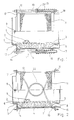
- FIGS. 1 to 5 are based on the same basic structure of a flexible line element for exhaust pipes of internal combustion engines in motor vehicles, which is why the same reference numerals are used in all these figures.
- FIGS. 12 and 13 contain a deviation from the above-mentioned basic structure by omitting the inner metal hose to be described, the possibility of such a deviation also applies to the other figures.
- the line element consists of a screw or ring-shaped corrugated metal bellows 1 with cylindrical bellows connecting ends 2, 3, the inside diameter of which can be smaller than the inside diameter of the bellows shafts 4 projecting inwards.
- a helically wound metal hose for example an agraff hose 5
- the outside diameter of which is smaller than the inside diameter of the bellows connecting ends 2, 3.
- the bellows connection ends 2, 3 and the end pieces 6 of the metal hose 5 are pressed together in the radial direction by the end pieces 6 being radially expanded while compressing the winding profile of the metal hose 5, with a possible radial play of the metal hose 5 relative to the bellows connection ends 2, 3 is bridged.
- support parts in the form of support rings 7, 8 are radially reduced in cross-section from the outside onto the bellows connecting ends 2, 3, so that overall a result of end pieces 6, bellows connecting ends 2, 3 and supporting rings 7, 8 results in a tightly compressed final assembly which offers a sufficiently solid and tight front edge for welding to a further pipeline.
- welding spots 9 can be provided distributed over the circumference of the support rings 7, 8.
- the bellows is encased by a braided hose 11, the ends of which are captured between the connection ends 2, 3 of the bellows and the support rings 7, 8 and fixed with them.
- the braided hose 11 is used in a known manner to axially support the two ends of the line element against one another, which is important in the case of suddenly occurring inertial forces. It thus prevents the bellows 1 from overstretching.
- a second braided hose 12 is now arranged, which is fixed with its left end with respect to FIG. 1 at the local connection end of the line element, for which purpose the support ring 7 forms an inner retaining ring 13, around which the end of the braided hose 12 is placed and on which the end of the braided tube 12 is fixed by an outer retaining ring 14 by the two retaining rings 13, 14 being pressed together.
- the other end of the braided hose 12 sits firmly between an inner retaining ring 15 and an outer retaining ring 16 in the same manner, but the retaining rings 15, 16 have no connection to the end of the line element there.
- webs 17, 18, which could also be designed as circumferential collars, extend radially outward and have bores for the reception of guide rods 19 parallel to the line element.
- the guide rods 19 are axially fixed on the part 17 by means of rings firmly connected to them, while they are guided on the part 18 so as to be displaceable. In order not to hinder a mutual lateral or angular offset of the ends of the line element, the guide rods have sufficient play in the bores of the webs 17, 18 that receive them.
- the rods 19, adjustable via nuts 20, support an abutment for helical compression springs 21, which are on the other hand Support part 18 and try to increase the distance between parts 17 and 18 as much as possible.
- the compressive preload of the springs 21 can be changed, and consequently also the strength with which the two braided sleeves 11, 12 lie against one another, so that the damping effect mentioned is adjusted in size or else adjusted after a longer operating time can be.
- the object according to FIG. 2 largely corresponds to the construction according to FIG. The only difference is that the spring forces pushing the two parts 17, 18 apart are formed by U-shaped bow springs 22 which are inserted with their free ends into bores of the parts 17, 18.
- the legs of the bow springs 22 can be given such a course that they adapt to the cylindrical jacket-shaped circumferential contour of the line element and, if necessary, also rest on the outer braided hose 12 in order to participate in the desired damping of the line element on this in a friction or sliding manner.
- the bow springs are intertwined in the manner shown in FIG. 2.
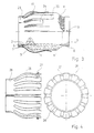
- FIG. 3 again shows, based on the basic structure of the line element described with reference to FIG. 1, an attenuator, which consists of fingers or sheet metal strips 23, 24 that come from the left connecting end of the line element in its longitudinal direction and have their free ends in contact with the first braided hose 11 start from a common retaining ring 25 fixed in the area of the left connecting end of the line element, which can be placed on the support ring 7 of the line element and fixed thereon, for example by spot welding.
- retaining ring 25 and support ring 7 are a common component.
- the fingers 23, 24 have curved curvature in the region of their free ends in the direction of the axis of the line element, with which they rest on the braided hose 11 and thus exert the damping effect already described with reference to FIGS. 1 and 2.
- a punctiform, linear or even flat contact with the braided tube 11 can be achieved by appropriate design of the fingers, depending on how the value of damping is desired.
- the fingers are made of a resilient material so that they rest against the braided tube 11 by their own spring force.
- the free ends of the fingers 26 which in this case are of equal length, by means of an externally fitted, self-resilient and, if necessary, adjustable clamping ring 27 in to hold defined system on the braided hose 11.
- the fingers 26 again start from a common retaining ring 28, which could be placed in a corresponding manner on the support ring 7 of the line element according to FIG. 3.
- the right representation in FIG. 4 shows the object according to the left representation as seen from the left, based on the drawing.
- FIG. 5 shows an example in which retaining rings 30, 31 with fingers 32, 33 are provided, starting from both ends of the line element, which interlock with one another in an interlocking manner and thus - also taking into account different lengths of the fingers - a large surface area of the braided hose 11 cover damping. 5 applies to the embodiment of FIG. 5 with respect to the functioning of the attenuators represented by the fingers 32, 33 correspondingly with reference to FIGS. 3 and 4.
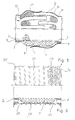
- FIG. 6 shows a variant of the embodiment according to FIG. 2.
- the second braided hose 12 is then connected to end rings 35, 36, one of which can be fixed on the corresponding connection end of the line element.
- a helical circumferential spring 37 is arranged between the end rings and is supported under axial pressure prestress against the end rings 35, 36 in such a way that it stretches the second braided hose 12 and thus tries to bring it into contact with the first braided hose 11.
- the effect of such a construction then corresponds to the mode of operation explained with reference to FIG. 2.
- the spring 37 is only fixed at one end to one of the support rings 7 and 8 (see FIG. 6a) or one of the end rings 35 and 36, while its other end is from support ring or end ring there is free at a distance.
- the spring 37 has an inner diameter in the relaxed state which is smaller than the outer diameter of the first Braided hose 11 or a second braided hose 12 pulled over it is in the installed state.
- the spring 37 presses radially onto the first braided hose 11 or the second braided hose 12 pulled over it, thus causing the damping friction on the first braided hose 11 or between the first and two braided hose and between the second braided hose 12 and the spring 37.
- FIGS. 8 and 8a show variants in that a helical circumferential spring 39 is formed from flat strip material so that it bears with a larger surface area on the braided hose 12 and 11 and a correspondingly greater damping effect compared to the braided hose can exercise.
- 8 again relates to a design according to which a second braided hose 12 is axially prestressed via end rings 35, 36, while FIG. 8a contains the case in which the spring 39 struck on the supporting ring 7 on one side has a smaller inner diameter than the outer diameter of the braid 11 or 12.
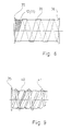
- 9 and 9a are in a development of the object according to FIG. 8 or 8a a supplement to the object according to FIG. 6 or 6a so that a flat ribbon spring 40 embraced by an oppositely wound spring 41 made of material with a circular cross section and radially with a supporting bias is applied.
- the first braided tube 11 of a line element which may again correspond to the basic structure of the line element according to FIG. 1, is surrounded by an attenuator, which extends from the left connecting end of the line element in its longitudinal direction and has its free ends in contact with the first braided tube 11
- the fingers 42 extend axially parallel to the line element in a manner resting on the first braided hose 11.
- a helical spring 44 is placed around the finger arrangement, the inner diameter of which in the relaxed state is smaller than the outer diameter of the finger arrangement 42 so that in the installed state the spring 44 presses the fingers 42 radially into contact with the first braided hose 11 in the installed state. This results in relative movement during operation-related movements of the line element and thus friction between the first braided hose 11 and the fingers 42, which brings about the desired damping. The frictional force is generated by the constricting action of the spring 44 on the fingers 42.
- Fig. 11 shows the collar 43 or 43a and the fingers 42 as an intermediate product coming from the punching, from which it can be seen that this cage arrangement can first be produced as a flat sheet metal stamped part, from which the collar 43 is then flanged up and the diecut is folded over the later one Axis of the line element of the basket shown in FIG. 10 arises or the ring 43a according to FIG. 10a is formed later by leaving the collar 43.
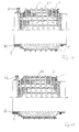
- FIG. 12 again shows in its entirety a line element according to FIG. 1, but omitting the inner metal hose 5, in which a damping member consisting of sheet metal fingers 50 extending axially parallel and regularly distributed over the circumference of the bellows 1 is arranged between the first braided hose 11 and bellows 1 is provided, which converge on a, in this case the left end in a common ring 51, which is integrated between the bellows connecting end 2 and the combination of the axial end of the braided hose 11 and the support ring 7 by radial pressing.
- a damping member consisting of sheet metal fingers 50 extending axially parallel and regularly distributed over the circumference of the bellows 1 is arranged between the first braided hose 11 and bellows 1 is provided, which converge on a, in this case the left end in a common ring 51, which is integrated between the bellows connecting end 2 and the combination of the axial end of the braided hose 11 and the support ring 7 by radial pressing.
- the fingers 50 extend over most of the length of the bellows 1 in a straight line and, if appropriate, the circumferential contour of the bellows 1 and the braided hose 11 are adapted so that they are in operation-related movements within the line element on the outside of the bellows 1 on the one hand and on the inside of the Braided hose 11, on the other hand, ben, and thus in particular to the latter cause the damping under discussion here.
- FIG. 13 shows a modification of the object according to FIG. 12 in such a way that, in the presence of a second braided tube 12, the finger arrangement 52 with rings 53 connecting it is arranged between the two braided tubes 11, 12 starting from the left end of the line element in the present case, here the outer or second braided hose 12 is fixed at both ends of the line element in order to pretension the finger arrangement 52 in the direction of the first braided hose 11 and at the same time to participate in the damping effect exerted by the fingers 52.
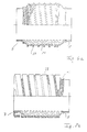
- FIGS. 14 to 16 correspond to the embodiments according to FIG. 10 and in particular FIG. 10a.
- a finger formation 60 formed by round material or wire material can be seen, which in turn is surrounded by a spring 61 corresponding to the spring 44 of the design according to FIGS. 10 and 10a is, that is, of a spring whose inner diameter is smaller than that Outside diameter of the unit surrounded by it, so that the spring constricts the fingers 60 radially and thus presses against the braided hose 11, the latter then being clamped radially against the corrugated hose 1.
- the wire-shaped fingers 60 are caught on one side, with reference to FIG. 14, on the left side between a support ring 7 and a further ring 62 and fixed there, while the spring 61 on the left side, starting from a fastening by means of a clamping screw 63, over the entire length the arrangement goes and at the other, according to FIG. 14 at the right end with the support ring 8, for example by welding.
- the construction according to FIG. 15 differs from that according to FIG. 14 only in that the wire-shaped fingers 64 have a wave-shaped course over their longitudinal extension, so that the spring 61 is better fixed in the axial direction with regard to the arrangement of your individual turns.
- FIG. 16 the arrangement of FIGS. 14 and 15 is guided from two sides towards the center of the line element, for which purpose the fingers 60, which can also be designed in the shape of the fingers 64 according to FIG. 15, in which FIG. 14 and 15 can be seen in each case at the two ends with end rings of U-shaped cross section 65, 66, for example by welding, which take the place of the support rings 7, 8 shown in the previous figures.
- the advantage of the designs according to FIGS. 14 to 16 over the designs according to FIGS. 3 to 5 and 10 to 13 be is that greater flexibility can be achieved.
- the band-shaped fingers used in FIGS. 3 to 5 and 10 to 13 can only optimally bend in one direction, namely the radial direction.
- the fingers made of round material according to FIGS. 14 to 16 can be bent equally well in any direction.
Landscapes
- Engineering & Computer Science (AREA)
- General Engineering & Computer Science (AREA)
- Mechanical Engineering (AREA)
- Chemical & Material Sciences (AREA)
- Combustion & Propulsion (AREA)
- Joints Allowing Movement (AREA)
- Exhaust Silencers (AREA)
Abstract
Es wird ein flexibles Leitungselement für Abgasleitungen von Verbrennungsmotoren bei Kraftfahrzeugen angegeben, das einen Balg aus Metall mit zylindrischen Anschlußenden und einen den Balg unmittelbar umgebenden Geflechtsschlauch aus Metalldraht aufweist, wobei diese Teile endständig zur Bildung der Anschlußenden des Leitungselementes innerhalb je eines zylindrischen Stützringes fest miteinander verbunden sind. Dabei ist vorgesehen, daß wenigstens ein von einem der Anschlußenden des Leitungselementes ausgehendes und im übrigen relativ zum Geflechtsschlauch bewegliches, flexibles Dämpfungsglied an den ersten Geflechtsschlauch in Anlage gebracht ist.
Description
Die Erfindung betrifft ein flexibles Leitungselement für Abgasleitungen von Verbrennungsmotoren bei Kraftfahrzeugen mit einem mit zylindrischen Anschlußenden versehenen, schraubengangförmig oder ringgewellten Balg aus Metall und einem den Balg unmittelbar umgebenden ersten Geflechtsschlauch aus Metalldraht, wobei gegebenenfalls Balg und erster Geflechtsschlauch endständig zur Bildung der Anschlußenden des Leitungselementes innerhalb eines zylindrischen Stützringes miteinander und mit diesem verpreßt und die Teile gegenseitig durch anheften verbunden sind.The invention relates to a flexible pipe element for exhaust pipes of internal combustion engines in motor vehicles with a cylindrical connection ends provided with a screw-shaped or ring-corrugated bellows made of metal and a first braided hose made of metal wire immediately surrounding the bellows, the bellows and the first braided hose possibly being terminal to form the connection ends of the pipe element within a cylindrical support ring pressed together and with this and the parts are mutually connected by tacking.
Ein Leitungselement dieser Gattung ist Gegenstand der älteren Patentanmeldung P 39 24 697.3-13. Es wird in der Regel als Zwischenstück in die im übrigen weitgehend starre Abgasleitung eingebaut, um Bewegungen und Schwingungen aufzunehmen und von der Weiterleitung an benachbarte Bauteile abzukoppeln, wie sie von der elastisch gelagerten Antriebsmaschine, Erschütterungen des Fahrzeuges, temperaturbedingten Längenänderungen etc. entstehen. Dabei gilt neben der Eigenschaft der Flexibilität die Aufmerksamkeit der Frage der Wärmedämmung, der Schallabsorption und der Dichtheit gegen Austritt von Abgasen, insbesondere in Verbindung mit Katalysatorfahrzeugen und verschärften Bestimmungen hinsichtlich Schall- und Abgasimmission.A line element of this type is the subject of the earlier
Beim Gegenstand der Voranmeldung ist darüber hinaus eine einfachere und fertigungsgünstigere Gestaltung angestrebt, wozu die zylindrischen Balganschlußenden einen Innendurchmesser aufweisen, der kleiner als der lichte Innenquerschnitt des Balges ist, und wozu ein zusätzlich koaxial im Balg angeordneter, ohne Dichtungseinlage gewickelter Metallschlauch, dessen Außenquerschnitt kleiner als der lichte Innenquerschnitt des Balges ist, an seinen innerhalb der Balganschlußenden gelegenen und mit diesen bündig abschließenden Endstücken unter Zusammendrücken des Schlauchprofils und Ausgleich der Toleranzen gegenüber dem Innenquerschnitt der Balganschlußenden radial aufgeweitet ist. Dabei ist vorteilhafterweise auf die Balganschlußenden je ein zylindrisches Stützteil von außen aufgesetzt, mit dem zugeordneten Balganschlußende sowie dem Endstück des Metallschlauches radial verpreßt und mit dem Balganschlußende über den Umfang mehrfach durch Anheften verbunden, beispielsweise verschweißt.In the subject of the prior notification, a simpler and more economical design is also sought, for which purpose the cylindrical bellows connection ends have an inner diameter that is smaller than the clear inner cross section of the bellows, and why an additionally coaxially arranged in the bellows, wrapped without a sealing insert, the outer cross section of which is smaller than the clear internal cross-section of the bellows is, at its ends located within the bellows connecting ends and flush with these end pieces, compressing the hose profile and compensating for tolerances with respect to the internal cross section of the bellows connecting ends. In this case, a cylindrical support part is advantageously placed on the bellows connection ends from the outside, radially pressed with the associated bellows connection end and the end piece of the metal hose, and connected to the bellows connection end several times over the circumference by tacking, for example welded.
Dieses Leitungselement hat in jeder Beziehung die von ihm erwarteten Gebrauchseigenschaften. Andererseits hat sich jedoch gezeigt, daß sich seine Fähigkeit zur Schwingungsdämpfung über die Standzeit gesehen verringert. Die Ursache hierfür wird im wesentlichen darin gesehen, daß der innere gewickelte Metallschlauch bzw. Agraffschlauch, der das hauptsächliche Dämpfungsglied für Schwingungen darstellt, mit zunehmender Laufleistung in seiner Dämpfungswirkung nachläßt. Ursache hierfür könnte ein gewisser Reibungsverschleiß in den einzelnen miteinander in formschlüssigem Eingriff befindlichen Wicklungen des Metallschlauches sein.This line element has the expected performance characteristics in every respect. On the other hand, however, it has been shown that its ability to dampen vibrations decreases over time. The reason for this is seen essentially in the fact that the inner wound metal hose or agraff hose, which is the main damping element for vibrations, decreases in its damping effect with increasing mileage. This could be due to a certain amount of frictional wear in the individual windings of the metal hose that are in positive engagement with one another.
Aufgabe der Erfindung ist es daher, ein Leitungselement der eingangs genannten Art mit einer zusätzlichen Dämpfung auszurüsten, die in gegebenenfalls auch nachstellbarer Weise eine bedeutende Standzeiterhöhung der Dämpfungseigenschaften garantiert, wobei insbesondere eine einfache und billige Konstruktion angestrebt und weitestgehend Unabhängigkeit von den Einflüssen des Abgasstromes erreicht werden soll.The object of the invention is therefore to equip a line element of the type mentioned at the outset with an additional damping which, in an optionally also adjustable manner, guarantees a significant increase in the service life of the damping properties, in particular a simple and inexpensive construction which is sought and largely independent of the influences of the exhaust gas flow should.
Diese Aufgabe ist ausgehend von einem Leitungselement der eingangs genannten Art mit der Erfindung prinzipiell dadurch gelöst, daß wenigstens ein von einem der Anschlußenden des Leitungselementes ausgehendes und im übrigen relativ zum Geflechtsschlauch bewegliches, flexibles Dämpfungsglied an den ersten Geflechtsschlauch in Anlage gebracht ist.Starting from a line element of the type mentioned at the outset, this object is principally achieved with the invention in that at least one flexible attenuator, which starts from one of the connection ends of the line element and is otherwise movable relative to the braided hose, is brought into contact with the first braided hose.
Diese grundsätzliche Maßnahme nach der Erfindung führt also dazu, daß wenigstens eines der Anschlußenden des Leitungselementes durch seine Relativbewegungen zum anderen Leitungsende in schwingungsdämpfender Weise über das Dämpfungsglied auf den ersten Geflechtsschlauch einwirkt so, daß die aus den Bewegungen des Leitungselementes resultierenden Bewegungen des ersten Geflechtsschlauches zwar grundsätzlich stattfinden können, dadurch aber gegenüber dem Dämpfungsglied reibungsbehaftete Relativbewegungen eintreten.This basic measure according to the invention therefore means that at least one of the connecting ends of the line element acts on the first braided hose in a vibration-damping manner via the damping member by its relative movements to the other end of the line, so that the movements of the first braided hose resulting from the movements of the line element are fundamentally can take place, but thereby occur relative movements relative to the attenuator.
Dadurch, daß das Dämpfungsglied auf der Außenseite des Balges angeordnet ist, ist es praktisch den abgasbedingten Belastungen, insbesondere Temperaturbelastungen entzogen, so daß hieraus eine negative Beeinflussung der Standzeit des Leitungselementes nicht mehr erwachsen kann.Due to the fact that the damping element is arranged on the outside of the bellows, it is practically removed from the exhaust gas-related loads, in particular temperature loads, so that a negative influence on the service life of the line element can no longer arise from this.
Durch die erfindungsgemäße Gestaltung des Dämpfungsgliedes paßt sich dieses an die normalen Bewegungsvorgänge des Leitungselementes in Axial- und Lateralrichtung an, schränkt also insbesondere dessen Beweglichkeit nirgendwo ein.Due to the design of the damping element according to the invention, it adapts to the normal movement processes of the line element in the axial and lateral directions, and thus in particular does not restrict its mobility anywhere.
Nach einer ersten Ausführungsform der Erfindung ist es zweckmäßig, daß das Dämpfungsglied ein zweiter, koaxial zum Leitungselement angeordneter und am ersten Geflechtsschlauch von außen anliegender Geflechtsschlauch ist, daß der zweite Geflechtsschlauch mit einem Ende am dortigen Anschlußende des Leitungselementes festgelegt ist, und daß das andere Ende des zweiten Geflechtsschlauches in Axialrichtung im Sinne einer Streckung gegebenenfalls ein- bzw. nachstellbar vorgespannt ist.According to a first embodiment of the invention, it is expedient that the damping member is a second braided hose which is arranged coaxially to the line element and which is adjacent to the first braided hose, that the second braided hose is fixed at one end to the connecting end of the line element there, and that the other end of the second braided hose is optionally preloaded or adjustable in the axial direction in the sense of an extension.
Hiermit werden zwei koaxial ineinander sitzende Geflechtsschläuche in gegenseitige Anlage gebracht, wobei der zweite Geflechtsschlauch vermöge seiner vorgespannten Streckung sich immer in Anlage am ersten Geflechtsschlauch befindet, da Geflechtsschläuche üblicher Bauform hren Durchmesser verringern, wenn sie gestreckt werden. Da andererseits der zweite Geflechtsschlauch nur an einem Ende gegenüber dem Leitungselement befestigt ist, befindet er sich in Anlage an dem ersten Geflechtsschlauch unabhängig von der Arbeitsweise bzw. Bewegungsstellung des ersten Geflechtsschlauches bzw. des mit ihm verbundenen Leitungselementes. Im Prinzip bewegen sich also bei der aufgabengemäßen Arbeitsweise des Leitungselementes die beiden genannten Geflechtsschläuche dauernd gegeneinander, was die erwünschte Dämpfungswirkung ergibt.With this, two coaxially nested braided sleeves are brought into mutual contact, the second braided sleeve being always in contact with the first braided sleeve due to its pretensioned stretch, since braided sleeves of conventional design reduce their diameter when they are stretched. On the other hand, since the second braided hose is attached to the line element only at one end, it is in contact with the first braided hose regardless of the mode of operation or the movement position of the first braided hose or the line element connected to it. In principle, the two mentioned braided sleeves constantly move against each other when the conduit element functions as intended, which results in the desired damping effect.
Zur näheren Ausgestaltung dieses Lösungsweges kann vorgesehen sein, daß der zweite Geflechtsschlauch mit seinen Enden zwischen Paaren von Halteringen gefaßt ist, daß das eine Halteringpaar mit dem zugeordneten Anschlußende des Leitungselementes bzw. dem dortigen Stützring verbunden ist, und daß das andere Halteringpaar durch gegebenenfalls ein- bzw. nachstellbare Federmittel in Bewegungsrichtung vom ersten Halteringpaar fort beaufschlagt bzw. vorgespannt ist.For a more detailed embodiment of this solution, it can be provided that the ends of the second braided hose are gripped between pairs of retaining rings, that one pair of retaining rings is connected to the associated connecting end of the line element or the supporting ring there, and that the other pair of retaining rings is connected by or adjustable spring means in the direction of movement away from the first pair of retaining rings or is biased.
Dabei kann vorgesehen sein, daß ausgehend von den Halteringpaaren sich nach radial außen erstreckende Stege von zum Leitungselement achsparallelen Führungsstangen durchquert sind, daß die Führungsstangen an einem der Stege axial festgelegt sind, und daß die Führungsstangen gegenüber dem anderen der Stege unter Federkraft gegen die Axialabstützung vorgespannt sind. Hier können die die Führungsstangen umgebenden Federn Schraubenfedern sein, die sich einerseits an einem gegebenenfalls verstellbaren Widerlager der Führungsstangen und andererseits am zugeordneten Steg abstützen.It can be provided that, starting from the retaining ring pairs, webs extending radially outwards are crossed by guide rods that are axially parallel to the line element, that the guide rods are axially fixed to one of the webs, and that the guide rods are prestressed against the other of the webs under spring force against the axial support are. Here the springs surrounding the guide rods can be helical springs which are supported on the one hand on an optionally adjustable abutment of the guide rods and on the other hand on the associated web.
Die so umrissene Lösung bietet einmal für den zweiten Geflechtsschlauch an seinem axial beweglichen bzw. freien Ende eine ausreichende Halterung bzw. Führung, wobei zu dieser Führung auch die Tatsache beiträgt, daß sich ja der zweite Geflechtsschlauch vermöge seiner in Streckrichtung gehenden Vorspannung dauernd auf dem ersten Geflechtsschlauch auflegt, somit sein kurzes, freies Ende eine ausreichende Abstützung erfährt.The solution outlined in this way provides sufficient support or guidance for the second braided sleeve at its axially movable or free end, the fact that the second braided sleeve, due to its pretensioning in the direction of extension, is permanently on the first Braid hose attaches, so that its short, free end is adequately supported.
Zum anderen ist aber auch in gegebenenfalls ein- oder nachstellbarer Weise eine genügende axiale Vorspannung des zweiten Geflechtsschlauches möglich, so daß einerseits die Größe der Dämpfungswirkung den jeweiligen Verhältnissen angepaßt werden kann, zum anderen aber auch nach längerer Betriebszeit eine Nachstel lung der Dämpfungswirkung durch Änderung der Axialvorspannung des zweiten Geflechtsschlauches vorgenommen werden kann.On the other hand, there is also sufficient axial preload in an adjustable or adjustable manner of the second braided hose possible, so that on the one hand the size of the damping effect can be adapted to the respective conditions, but on the other hand, even after a long period of operation, the damping effect can be adjusted by changing the axial preload of the second braided hose.
Fußend im wesentlichen auf der vorstehenden Konstruktion kann jedoch auch vorgesehen sein, daß von den Halteringpaaren nach radial außen sich erstreckende Stege ausgehen, und daß zwischen die Stege U-förmig gebogene Bügelfedern mit ihren freien Enden eingespannt sind. Hier werden also die erwähnten Führungsstangen mit den sie umgebenden Schraubenfedern ersetzt durch die genannten Bügelfedern, die auf der anderen Seite den Vorteil haben können, daß sie mit ihrem zwischen den Stegen gelegenen Teil in Anlage an dem zweiten Geflechtsschlauch sind und damit die erwünschte Dämpfungswirkung unterstützen, wobei zweckmäßigerweise die U-förmigen Bügelfedern zueinander verschränkt angeordnet werden können.Basically based on the above construction, however, it can also be provided that webs extending radially outward extend from the retaining ring pairs, and that U-shaped bow springs are clamped with their free ends between the webs. So here the mentioned guide rods with the helical springs surrounding them are replaced by the above-mentioned bow springs, which on the other hand can have the advantage that with their part located between the webs they are in contact with the second braided hose and thus support the desired damping effect, the U-shaped bow springs can advantageously be arranged interlaced with one another.
Als Alternative zur vorstehend geschilderten Ausführungsform kann auch vorgesehen sein, daß von den Halteringpaarensich nach radial außen erstreckende Stege in Form umlaufender Bunde ausgehen und daß zwischen die Bunde wenigstens eine schraubengangförmig umlaufende Feder mit ihren freien Enden unter Axialbelastung eingespannt ist.As an alternative to the embodiment described above, it can also be provided that webs extending radially outward extend from the retaining ring pairs in the form of circumferential collars and that at least one helical circumferential spring is clamped with its free ends under axial load between the collars.
Nach einer weiteren Ausführungsform gemäß der Erfindung kann ein Lösungsweg vorteilhaft sein, der vorsieht, daß das Dämpfungsglied durch vom Anschlußende des Leitungselementes in dessen Längsrichtung ausgehende, mit ihren freien Enden am ersten Geflechtsschlauch von außen in Anlage befindliche Finger bzw. Blech- oder Drahtstreifen gebildet ist. Bei einer solchen Bauform erstrecken sich die in Axialrichtung im wesentlichen steifen Finger korbförmig von einem Anschlußende des Leitungselementes ausgehend über dessen Außenbereich und liegen mit ihren freien Enden auf dem ersten Geflechtsschlauch an, um so in von der Arbeitsweise des Leitungselementes unabhängiger Art durch Relativbewegung gegenüber dem ersten Geflechtsschlauch die gewünschte Dampfung herbeizuführen.According to a further embodiment according to the invention, a solution can be advantageous which provides that the attenuator with its from the connecting end of the line element in the longitudinal direction free ends on the first braided tube from the outside in contact with fingers or sheet metal or wire strips is formed. In such a design, the fingers, which are essentially stiff in the axial direction, extend in a basket-shaped manner from a connection end of the line element over its outer region and rest with their free ends on the first braided hose, so as to be independent of the mode of operation of the line element by relative movement with respect to the first Braid hose to bring about the desired damping.
Hier kann vorgesehen sein, daß die Finger von einem gemeinsamen, im Bereich des Anschlußendes festgelegten Haltering ausgehen, der zweckmäßig durch den dortigen Stützring gebildet ist.It can be provided here that the fingers start from a common retaining ring which is fixed in the region of the connection end and which is expediently formed by the support ring there.
Die Fingerenden können gegen den ersten Geflechtsschlauch federnd vorgespannt sein, um sich immer an diesem in Anlage zu befinden. Es besteht jedoch auch die Möglichkeit, daß die Fingerenden durch einen von außen aufgesetzten, federnden und gegebenenfalls nachstellbaren Spannring gegen den ersten Geflechtsschlauch in Anlage gehalten sind. Gerade bei diesem Lösungsweg lassen sich höhere Anlage- und damit Reibkräfte zwischen Finderenden und ersten Geflechtsschlauch erzielen. Ferner läßt sich nach längerer Betriebszeit die Anlagekraft der Fingerenden gegenüber dem ersten Geflechtsschlauch korrigieren bzw. nachstellen, sofern keine selbsttätig konstante Nachstellung erfolgen soll.The finger ends can be resiliently biased against the first braided tube so that it is always in contact with it. However, there is also the possibility that the finger ends are held against the first braided hose by an externally attached, resilient and possibly adjustable clamping ring. With this solution in particular, higher contact and thus frictional forces can be achieved between the finder ends and the first braided hose. Furthermore, the contact force of the finger ends with respect to the first braided tube can be corrected or adjusted after a long period of operation, provided that no automatic constant adjustment should be made.
Nach einer anderen Bauform kann vorgesehen sein, daß die Finger von einem zweiten, an ihnen gegebenenfalls axial vorgespannt anliegenden, koaxial zum Leitungselement angeordneten Geflechtsschlauch außen umgeben sind und daß dieser zweite Geflechtsschlauch endständig an den Anschlußenden des Leitungselementes festgelegt ist. Hier ist also in Abhängigkeit von der Bewegung des Leitungselementes die Anlage der Finger am ersten Geflechtsschlauch durch den zweiten Geflechtsschlauch gewährleistet, wobei sich dämpfende Reibung zwischen den Fingern und beiden Geflechtsschläuchen ergibt.According to another design, it can be provided that the fingers of a second, possibly axially on them biased braided hose arranged coaxially to the line element are surrounded on the outside and that this second braided hose is fixed at the terminal ends of the line element. Here, depending on the movement of the line element, the contact of the fingers on the first braided hose is ensured by the second braided hose, with damping friction between the fingers and the two braided hoses.
In einer dem Vorstehenden vergleichbaren Weise kann vorgesehen sein, daß die Finger von wenigstens einem sich im wesentlichen über die Länge des Leitungselementes erstreckenden Federelement in Form einer Schraubenfeder umgeben sind und daß der Innendurchmesser des Federelementes in dessen entspannten Zustand kleiner als der Außendurchmesser der Fingeranordnung ist. Hier ist es also das Federelement in Form einer Schraubenfeder, das die Finger in Anlage an den ersten Geflechtsschlauch hält und damit die dämpfende Reibwirkung zwischen Fingern und erstem Geflechtsschlauch garantiert.In a manner comparable to the above, it can be provided that the fingers are surrounded by at least one spring element in the form of a helical spring which extends essentially over the length of the line element and that the inner diameter of the spring element in its relaxed state is smaller than the outer diameter of the finger arrangement. So here it is the spring element in the form of a helical spring that holds the fingers in contact with the first braided hose and thus guarantees the damping friction effect between fingers and the first braided hose.
Nach einer weiter anderen Ausführungsform der Erfindug kann es vorteilhaft sein, daß das Dämpfungsglied durch wenigstens eine von wenigstens einem Anschlußende in dessen Längsrichtung ausgehende, mit ihrem Innenquerschnitt am ersten Geflechtsschlauch unter Radialspannung in Anlage befindliche Schraubenfeder gebildet ist. Eine solche einseitig festgelegte Schraubenfeder befindet sich ähnlich, wie dies bei den vorstehend diskutierten Fingern der Fall ist, in reibender Anlage am ersten Geflechtsschlauch und dämpft damit dessen Bewegung. Dabei kann es zweckmäßig sein, daß der Innenquerschnitt der Feder abweichend vom Außenquerschnitt des ersten Geflechtsschlauches ausgebildet ist, also beispielsweise eine ovale Form hat, so daß sich eine Anlage zwischen Feder und Geflechtsschlauch nicht üder die gesamte Innenkontur der Feder ergibt. Damit kann die Größe der durch die Feder auf den Geflechtsschlauch ausgeübten Dämpfungswirkung konstruktiv eingestellt bzw. gesteuert werden.According to a further different embodiment of the invention, it may be advantageous for the damping member to be formed by at least one helical spring, starting from at least one connecting end in its longitudinal direction and having its inner cross section in contact with the first braided hose under radial tension. A helical spring of this type, which is fixed on one side, is located, as is the case with the fingers discussed above, in frictional contact with the first braided hose and thus dampens its movement. It can be expedient that the inner cross section of the spring is formed differently from the outer cross section of the first braided hose, that is, for example, has an oval shape, so that there is no contact between the spring and the braided hose over the entire inner contour of the spring. In this way, the size of the damping effect exerted by the spring on the braided hose can be structurally adjusted or controlled.
Für die vorstehend genannten Fälle kann das Federmaterial Kreisquerschnitt haben. Genausogut kann jedoch auch Federmaterial in Frage kommen, welches Rechteckquerschnitt nach Art eines Flachbandes aufweist, wobei die Feder dann mit einer der größeren Oberflächen am ersten Geflechtsschlauch anliegt. Auch durch diese Maßnahmen läßt sich die Größe der dämpfenden Reibung zwischen Feder und erstem Geflechtsschlauch konstruktiv vorherbestimmen.For the cases mentioned above, the spring material can have a circular cross section. However, spring material which has a rectangular cross section in the manner of a flat strip can also be used, the spring then resting with one of the larger surfaces on the first braided tube. These measures also allow the size of the damping friction between the spring and the first braided hose to be predetermined in terms of construction.
Auch ist es aus den von den vorgenannten Fäll en denkbar, daß eine den ersten Geflechtsschlauch umgebende Feder mit Rechteckquerschnitt innerhalb einer gegebenenfalls gegenläufig gewundenen Feder mit Kreis- oder Rechteckquerschnitt angeordnet ist, um die Reibungs- und damit die Dämpfungswirkung zu beeinflussen, insbesondere zu vergrößern.It is also conceivable from the aforementioned cases that a spring with a rectangular cross-section surrounding the first braided hose is arranged within an optionally counter-clockwise wound spring with a circular or rectangular cross-section in order to influence, in particular to increase, the friction and thus the damping effect.
Nach einer wiederum anderen Ausführungsform kann es zweckmäßig sein, daß das Dämpfungsglied durch vom Anschlußende des Leitungselementes in dessen Längsrichtung ausgehende, zwischen Balg und erstem Geflechtsschlauch angeordnete Finger bzw. Blechstreifen gebildet ist, wobei auch hier die Finger von einem gemeinsamen, im Bereich des Anschlußendes festgelegten Haltering ausgehen können. Damit ist das Dämpfungsglied in den Bereich zwischen Balg und erstem Geflechtsschlauch verlegt, wo es gleichermaßen auf den ersten Geflechtsschlauch und den Balg wirken kann, indem die axial Relativbewegungen dieser beiden Teile zu Reibung gegenüber dem Dämpfungsglied in Form der Finger bzw. Blechstreifen führt. Hiermit ist also ein Beispiel dafür gegeben, daß das Dämpfungsglied auf den ersten Geflechtsschlauch nicht nur von außen sondern auch von innen einwirken kann, wobei im letztgenannten Falle die Effektivität des Dämfpungsgliedes durch dessen gleichzeitige Einwirkung auch auf den Balg erhöht wird.According to yet another embodiment, it may be expedient for the damping member to be formed by fingers or sheet metal strips, which extend from the connection end of the line element in its longitudinal direction and are arranged between the bellows and the first braided hose, the fingers also being of a common area of the connection end fixed retaining ring can go out. The damping member is thus moved into the area between the bellows and the first braided hose, where it can act equally on the first braided hose and the bellows, in that the relative axial movements of these two parts lead to friction with the damping member in the form of the fingers or sheet metal strips. This is an example of the fact that the damping member can act on the first braided hose not only from the outside but also from the inside, and in the latter case the effectiveness of the damping member is increased by its simultaneous action on the bellows.
In weiterer Ausführung des erfindungsgemäßen Lösungsgedankens kann bei den entsprechenden vorgenannten Bauformen vorgesehen sein, daß je ein Dämpfungsglied mit Fingern von beiden Enden des Leitungselementes ausgehend vorgesehen ist. Es wird also von beiden Enden des Leitungselementes ausgehend jeweils voneinander getrennt das Dämpfungsglied angebracht. Um hier gegebenenfalls bestehenden Platzproblemenen gerecht zu werden, kann vorgesehen sein, daß die sich gegenläufig erstreckenden Finger verzahnungsförmig ineinander greifend angeordnet sind, wobei es durchaus auch vorteilhaft sein kann, daß die Finger unterschiedliche Länge aufweisen, um jeweils - über die axiale Länge des Leitungselementes gesehen - an möglichst vielen unterschiedlichen Axialpositionen wirksam zu werden.In a further embodiment of the idea of the solution according to the invention, it can be provided in the corresponding above-mentioned designs that an attenuator with fingers is provided starting from both ends of the line element. Starting from both ends of the line element, the attenuator is therefore attached separately from each other. In order to do justice to any existing space problems here, it can be provided that the oppositely extending fingers are arranged so as to interlock with one another, although it can also be advantageous for the fingers to have different lengths, in each case - as seen over the axial length of the line element - to be effective in as many different axial positions as possible.
Was die Anlage der Finger bzw. Fingerenden gegenüber dem ersten Geflechtsschlauch bzw. dem Balg betrifft, so kann diese je nach den Umständen des Einzelfalles punktförmig, linienförmig oder flächenförmig gestaltet sein, indem der mit dem ersten Geflechtsschlauch bzw. dem Balg in Berührung kommende Teil der Finger entsprechend quer zur Längsachse des Leitungselementes bzw. parallel zu dessen Längsachse gewölbt ist. Auf diese Weise läßt sich zusätzlich die Größe des gegenseitigen Anlagebereiches zwischen erstem Geflechtsschlauch und Dämpfungsglied und damit schließlich auch die Größe der Dämpfungswirkung beeinflussen.As far as the contact of the fingers or finger ends with respect to the first braided tube or the bellows is concerned, depending on the circumstances of the individual case, this can be punctiform, be linear or sheet-like in that the part of the fingers that comes into contact with the first braided tube or the bellows is correspondingly curved transversely to the longitudinal axis of the line element or parallel to its longitudinal axis. In this way, the size of the mutual contact area between the first braided sleeving and the attenuator and thus ultimately the size of the damping effect can also be influenced.
In diesem Zusammenhang können die Finger auch über ihre Längserstreckung wellenförmig zur intermittiertenden Anlage an den ersten Geflechtsschlauch ausgebildet sein. Diese Ausbildung empfiehlt sich besonders für Finger aus Drahtmaterial zur Schaffung bestimmter Reibungsverhältnisse gegenüber dem Geflechtsschlauch, wobei solche Finger aus Drahtmaterial gegenüber denen aus Blechstreifen den Vorzug allseitiger Biegbarkeit haben, so daß sie die Flexibilität des Leitungselementes kaum beeinflussen.In this context, the fingers can also be designed in a wave-like manner over their longitudinal extent for intermittent contact with the first braided tube. This training is particularly recommended for fingers made of wire material in order to create certain frictional relationships with the braided hose, such fingers made of wire material being more flexible than those made of sheet metal strips, so that they hardly influence the flexibility of the line element.
Für alle vorstehend geschilderten und vergleichbaren Lösungswege mag gemeinsam noch gelten, daß für die Relativbewegung zwischen erstem Geflechtsschlauch und Dämpfungsglied die Anbringung verschleißhemmender bzw. die Gleitbewegung erleichternder Mittel vorteilhaft sein kann. Hierfür eignet sich in an sich bekannter Weise die Verwendung gleitfähiger Materialien wie Kupfer, Messing oder temperaturbeständiger Kunststoff, mit denen die in Rede stehenden Teile beispielsweise beschichtet sein können. Andererseits kann beispielsweise bei dem ersten und zweiten Geflechtsschlauch die Einfügung von sogenannten Opferdrähten aus Kupfer oder Messing vorgesehen sein.For all of the above-described and comparable solutions, it may still apply in common that the attachment of anti-wear agents or agents that facilitate the sliding movement can be advantageous for the relative movement between the first braided hose and the damping member. The use of lubricious materials such as copper, brass or temperature-resistant plastic, with which the parts in question can be coated, for example, is suitable for this in a manner known per se. On the other hand, for example, the insertion of so-called sacrificial wires made of copper or brass can be provided for the first and second braided sleeving.
Schließlich kann auch im vorliegenden Falle die Konstruktion so gestaltet sein, daß, wie bereits in der Beschreibungseinleitung erwähnt, im Balg koaxial ein ohne Dichtungseinlage gewickelter Metallschlauch angeordnet ist, daß der Außenquerschnitt des Metallschlauches kleiner ist als der lichte Innenquerschnitt des Balges ist, und daß der Metallschlauch endständig mit den Anschlußenden des Leitungselementes verpreßt und gegebenenfalls durch Anheften verbunden ist.Finally, also in the present case, the construction can be designed such that, as already mentioned in the introduction to the description, a metal hose without a sealing insert is coaxially arranged in the bellows, that the outer cross section of the metal hose is smaller than the clear inner cross section of the bellows, and that Metal hose is pressed terminally with the connection ends of the line element and, if necessary, connected by tacking.
Weitere wesentliche Merkmale und Einzelheiten der Erfindung ergeben sich aus der nachfolgenden Beschreibung von Ausführungsformen, die auf der Zeichnung dargestellt sind. In der Zeichnung zeigen die
- Fig. 1 bis 3 und 5 verschiedene Bauformen des Erfindungsgegenstandes in Seitenansicht, teilweise dabei im Axialschnitt;
- Fig. 4 eine Einzelheit aus Fig. 3 in abgeänderter Form sowohl in Seitenansicht als auch in axialer Schnittansicht bezogen auf Fig. 3 von links gesehen und
- Fig. 6 bis 16 weitere Ausführungsformen der Erfindung, teilweise in vereinfachten Ausschnitten gemäß der Darstellungsform nach den vorhergehenden Figuren.
- Figures 1 to 3 and 5 different designs of the subject invention in side view, partially in axial section.
- Fig. 4 shows a detail of Fig. 3 in a modified form both in side view and in axial sectional view with respect to Fig. 3 seen from the left and
- 6 to 16 further embodiments of the invention, partly in simplified sections according to the form of representation according to the preceding figures.
Die in den Fig. 1 bis 5 gezeigten Ausführungsformen gehen von dem gleichen Grundaufbau eines flexiblen Leitungselementes für Abgasleitungen von Verbrennungsmotoren bei Kraftfahrzeugen aus, weshalb insoweit auch in allen diesen Figuren die gleichen Bezugszeichen verwendet werden.The embodiments shown in FIGS. 1 to 5 are based on the same basic structure of a flexible line element for exhaust pipes of internal combustion engines in motor vehicles, which is why the same reference numerals are used in all these figures.
Der Grundaufbau wird nachfolgend anhand der Fig. 1 erläutert, ohne daß diese Erläuterung im einzelnen noch einmal für die weiteren Figuren wiederholt würde. Soweit die Fig. 12 und 13 eine Abweichung von dem genannten Grundaufbau dadurch enthalten, daß der noch zu beschreibende innere Metallschlauch fortgelassen ist, gilt die Möglichkeit einer solchen Abweichung auch für die übrigen Figuren.The basic structure is explained below with reference to FIG. 1, without this explanation being repeated again in detail for the other figures. To the extent that FIGS. 12 and 13 contain a deviation from the above-mentioned basic structure by omitting the inner metal hose to be described, the possibility of such a deviation also applies to the other figures.
Gemäß Fig. 1 besteht das Leitungselement aus einem schrauben- oder ringförmig gewellten Metallbalg 1 mit zylindrischen Balganschlußenden 2, 3, deren Innendurchmesser kleiner als der Innendurchmesser der nach innen ragenden Balgwellen 4 sein kann.1, the line element consists of a screw or ring-shaped corrugated metal bellows 1 with cylindrical bellows connecting ends 2, 3, the inside diameter of which can be smaller than the inside diameter of the
In den Balg 1 ist ein schraubengangförmig gewickelter Metallschlauch, beispielsweise ein Agraffschlauch 5, eingesetzt, dessen Außendurchmesser kleiner als der Innendurchmesser der Balganschlußenden 2, 3 ist.In the
An den gemeinsamen Enden sind die Balganschlußenden 2, 3 und die Endstücke 6 des Metallschlauches 5 in Radialrichtung miteinander verpreßt, indem die Endstücke 6 unter Zusammendrücken des Wickelprofiles des Metallschlauches 5 radial aufgeweitet sind, wobei gleichzeitig ein eventuelles Radialspiel des Metallschlauches 5 gegenüber den Balganschlußenden 2, 3 überbrückt wird. Gleichzeitig sind von außen auf die Balganschlußenden 2, 3 gesetzte Stützteile in Form von Stützringen 7, 8 radial im Querschnitt verringert, so daß sich insgesamt im Ergebnis aus Endstücken 6, Balganschlußenden 2, 3 und Stützringen 7, 8 ein fest zusammengedrückter Abschlußverbund ergibt, der zum Anschweißen an eine weiterführende Rohrleitung eine genügend massive und dichte Stirnkante bietet. Um den genannten Anschlußverbund weiter stabil zu gestalten, können über den Umfang der Stützringe 7, 8 verteilt Schweißpunkte 9 vorgesehen sein.At the common ends, the bellows connection ends 2, 3 and the
Wie weiterhin aus Fig. 1 ersichtlich, ist der Balg durch einen Geflechtsschlauch 11 ummantelt, dessen Enden zwischen den Anschlußenden 2, 3 des Balges und den Stützringen 7, 8 eingefangen und mit diesen festgelegt sind. Der Geflechtsschlauch 11 dient in bekannter Weise der Axialabstützung der beiden Enden des Leitungselementes gegeneinander, was bei plötzlich auftretenden Massenkräften von Bedeutung ist. Er verhindert also eine Überdehnung des Balges 1.1, the bellows is encased by a
Über dem Geflechtsschlauch 11 ist nunmehr ein zweiter Geflechtsschlauch 12 angeordnet, der mit seinem bezogen auf Fig. 1 linken Ende am dortigen Anschlußende des Leitungselementes festgelegt ist, wozu der Stützring 7 einen inneren Haltering 13 bildet, um den das Ende des Geflechtsschlauches 12 gelegt und auf dem das Ende des Geflechtsschlauches 12 durch einen äußeren Haltering 14 festgelegt ist, indem die beiden Halteringe 13, 14 miteinander verpreßt sind.Above the
Das andere Ende des Geflechtsschlauches 12 sitzt zwischen einem inneren Haltering 15 und einem äußeren Haltering 16 in der gleichen Weise fest, wobei jedoch die Halteringe 15, 16 keine Verbindung mit dem dortigen Ende des Leitungselementes haben.The other end of the
Andererseits gehen vom Stützring 7 sowie Haltering 15 nach radial außen Stege 17, 18, die auch als umlaufende Bunde gestaltet sein könnten, aus, die Bohrungen für die zum Leitungselement achsparallele Aufnahme von Führungsstangen 19 aufweisen. Die Führungsstangen 19 sind am Teil 17 axial durch mit ihnen fest verbundene Ringe form- und kraftschlüssig festgelegt, während sie am Teil 18 verschieblich geführt sind. Um einen gegenseitigen seitlichen oder winkelmäßigen Versatz der Enden des Leitungselementes nicht zu behindern, haben die Führungsstangen ausreichendes Spiel in den sie aufnehmenden Bohrungen der Stege 17, 18. Ferner tragen die Stangen 19 über Muttern 20 einstellbar ein Widerlager für Schraubendruckfedern 21, die sich andererseits am Teil 18 abstützen und damit trachten, den Abstand zwischen den Teilen 17 und 18 möglichst zu vergrößern.On the other hand, from the
Diese axiale Vorspannung überträgt sich auf den Geflechtsschlauch 12 und führt bei diesem in an sich bekannter Weise zu einer Durchmesserreduktion und damit zu einer dauernden Anlage des Geflechtsschlauches 12 auf dem Geflechtsschlauch 11. Dies ergibt eine Dämpfung für das Leitungselement, da die beiden genannten Geflechtsschläuche unabhängig voneinander ineinander verschieblich sind.This axial pretension is transferred to the
Wie durch die Einstellbarkeit der Muttern 12 veranschaulicht, kann die Druckvorspannung der Federn 21 verändert werden, folglich auch die Festigkeit, mit der die beiden Geflechtsschläuche 11, 12 aneinanderliegen, so daß die genannte Dämpfungswirkung in ihrer Größe eingestellt oder aber auch nach einer längeren Betriebszeit nachgestellt werden kann.As illustrated by the adjustability of the nuts 12, the compressive preload of the
Der Gegenstand gemäß Fig. 2 stimmt mit dem gemäß Fig. konstruktiv weitestgehend überein. Unterschiedlich ist lediglich, daß die die beiden Teile 17, 18 auseinanderdrückenden Federkräfte durch U-förmig gebogene Bügelfedern 22 gebildet sind, die mit ihren freien Enden in Bohrungen der Teile 17, 18 eingesteckt sind. Den Schenkeln der Bügelfedern 22 kann ein solcher Verlauf gegeben werden, daß sie sich der zylindermantelförmigen Umfangskontur des Leitungselementes anpassen und gegebenenfalls auch auf dem äußeren Geflechtsschlauch 12 anliegen, um auf diesem reibend bzw. gleitend an der gewünschten Dämpfung des Leitungselementes teilzuhaben.The object according to FIG. 2 largely corresponds to the construction according to FIG. The only difference is that the spring forces pushing the two
Um ein unerwünschtes Abheben der Bügelfedern vom Geflechtsschlauch 12 zu verhindern, sind die Bügelfedern in der aus Fig. 2 ersichtlichen Weise ineinander verschlungen.In order to prevent undesired lifting of the bow springs from the braided
Fig. 3 zeigt wieder ausgehend von dem Grundaufbau des anhand der Fig. 1 geschilderten Leitungselementes ein Dämpfungsglied, das aus vom linken Anschlußende des Leitungselementes in dessen Längsrichtung ausgehenden, mit ihren freien Enden am ersten Geflechtsschlauch 11 in Anlage befindlichen Fingern bzw. Blechstreifen 23, 24 von einem gemeinsamen, im Bereich des linken Anschlußendes der Leitungselementes festgelegten Haltering 25 ausgehen, der auf den Stützring 7 des Leitungselementes aufgesetzt und an diesem beispielsweise durch Punktschweißen festgelegt sein kann. Dabei könnte auch die Möglichkeit bestehen, daß Haltering 25 und Stützring 7 ein gemeinsames Bauteil sind.FIG. 3 again shows, based on the basic structure of the line element described with reference to FIG. 1, an attenuator, which consists of fingers or sheet metal strips 23, 24 that come from the left connecting end of the line element in its longitudinal direction and have their free ends in contact with the
Die Finger 23, 24 haben im Bereich ihrer freien Enden in Richtung auf die Achse des Leitungselementes gewölbte Krümmung, mit der sie auf dem Geflechtsschlauch 11 anliegen und so die bereits anhand der Fig. 1 und 2 geschilderte Dämpfungswirkung ausüben. Was die Größe und Gestalt der Anlagefläche zwischen den Fingern und dem Geflechtsschlauch 11 betrifft - und dies gilt auch für die nachfolgenden Ausführungsformen -, so kann durch entsprechende Gestaltung der Finger eine punktförmige, linienförmige oder auch flächige Anlage am Geflechtsschlauch 11 erreicht werden, je nachdem, wie der Wert der Dämpfung gewünscht wird.The
Bei der in Fig. 3 dargestellten Ausführungsform sind die Finger aus einem federnden Material hergestellt, so daß sie vermöge eigener Anfederkraft an dem Geflechtsschlauch 11 anliegen. Es besteht jedoch, wie anhand des Beispieles gemäß Fig. 4 ersichtlich, auch die Möglichkeit, hier grundsätzlich kein selbstfederndes Material zu verwenden, sondern die freien Enden der in diesem Falle gleich langen Finger 26 durch einen außen aufgesetzten, selbstfedernden und gegebenenfalls nachstellbaren Spannring 27 in definierter Anlage an dem Geflechtsschlauch 11 zu halten. Im übrigen gehen auch bei dem in Fig. 4 dargestellten Beispiel die Finger 26 wieder von einem gemeinsamen Haltering 28 aus, der in entsprechender Weise auf dem Stützring 7 des Leitungselementes gemäß Fig. 3 aufgesetzt sein könnte.In the embodiment shown in Fig. 3, the fingers are made of a resilient material so that they rest against the
Die rechte Darstellung in Fig. 4 zeigt den Gegenstand gemäß der linken Darstellung von - bezogen auf die Zeichnung - links aus gesehen.The right representation in FIG. 4 shows the object according to the left representation as seen from the left, based on the drawing.
Die Ausführungsform gemäß Fig. 5 zeigt ein Beispiel, bei dem von beiden Enden des Leitungselementes ausgehend Halteringe 30, 31 mit Fingern 32, 33 vorgesehen sind, die verzahnungsförmig sich überdeckend ineinander greifen und somit - auch unter Berücksichtigung unterschiedlicher Längen der Finger - einen großen Oberflächenbereich des Geflechtsschlauches 11 dämpfend abdecken. Im übrigen gilt für die Ausführungsform gemäß Fig. 5 bezüglich der Funktionsweise der durch die Finger 32, 33 dargestellte Dämpfungsglieder das anhand der Fig. 3 und 4 Erläuterte entsprechend.The embodiment according to FIG. 5 shows an example in which retaining rings 30, 31 with
Fig. 6 zeigt eine Variante zur Ausführungsform gemäß Fig. 2. Danach ist der zweite Geflechtsschlauch 12 mit Endringen 35, 36 verbunden, von denen einer am entspechenden Anschlußende des Leitungselementes festgelegt sein kann. Zwischen den Endringen ist eine schraubengangförmige umlaufende Feder 37 angeordnet und unter axialer Druckvorspannung gegen die Endringe 35, 36 abgestützt so, daß sie den zweiten Geflechtsschlauch 12 zu strecken und damit auf dem ersten Geflechtsschlauch 11 in Anlage zu bringen sucht. Die Wirkung einer derartigen Konstruktion entspricht dann wieder der anhand der Fig. 2 erläuterten Funktionsweise.FIG. 6 shows a variant of the embodiment according to FIG. 2. The
Die Bauform gemäß Fig. 6 ist jedoch auch so denkbar, daß die Feder 37 nur mit einem Ende an einem der Stützringe 7 bzw. 8 (siehe Fig. 6a) oder einem der Endringe 35 bzw. 36 festgelegt ist, während ihr anderes Ende vom dortigen Stützring bzw. Endring mit Abstand frei ist. Gleichzeitig hat die Feder 37 im entspannten Zustand einen Innendurchmesser, der kleiner als der Außendurchmesser des ersten Geflechtsschlauch 11 bzw. eines darüber gezogenen zweiten Geflechtsschlauch 12 im eingebauten Zustand ist. Auf diese Weise drückt die Feder 37 radial auf den ersten Geflechtsschlauch 11 bzw. den über diesen gezogenen zweiten Geflechtsschlauch 12 und verursacht damit die däpfende Reibung am ersten Geflechtsschlauch 11 bzw. zwischen erstem und zwei tem Geflechtsschlauch sowie zwischen zweitem Geflechtsschlauch 12 und Feder 37.6 is also conceivable in such a way that the
Im Rahmen dieser zuletzt genannten Variationsmöglichkeiten besteht gemäß Fig. 7, die eine Seiten- und Stirnansicht des Erfindungsgegenstandes zeigt, die Möglichkeit, eine der Feder 37 entsprechende Feder 38 wenigstens teilweise in ihrer Innenquerschnittsform abweichend von dem Außenquerschnitt des ersten Geflechtsschlauches 11 bzw. des zweiten Geflechtsschlauches 12 auszubilden so, daß nicht die gesamte Innenkontur der Feder 38 am jeweiligen Geflechtsschlauch anliegt sondern die Größe des Anlagebereiches durch die Orte der Übereinstimmung der Innenkontur der Feder 38 mit der Außenkontur des Geflechtsschlauches 11 bzw. 12 bestimmt ist. Dabei kann, wie insbesondere aus der linken Ansicht der Fig. 7 ersichtlich, über die Länge der Feder 38 ein Wechsel deren Verlaufes und damit eine Änderung deren Innenquerschnittes stattfinden.7, which shows a side and front view of the subject matter of the invention, there is the possibility, at least partially, of a
Zu den insoweit anhand der Fig. 6, 6a und 7 geschilderten Ausführungsmöglichkeiten zeigen Fig. 8 und 8a Varianten dahingehend, daß eine schraubengangförmige umlaufende Feder 39 aus Flachbandmaterial ausgebildet ist so, daß sie mit einer größeren Oberfläche an dem Geflechtsschlauch 12 bzw. 11 anliegen und eine dementsprechend größere Dämpfungswirkung gegenüber dem Geflechtsschlauch ausüben kann. Dabei betrifft wieder Fig. 8 eine Bauform, gemäß der ein zweiter Geflechtsschlauch 12 über Endringe 35, 36 axial vorgespannt wird, während Fig. 8a den Fall enthält, daß die einseitig am Stützring 7 angeschlagene Feder 39 einen kleineren Innendurchmesser aufweist als den Außendurchmesser des Geflechts 11 bzw. 12.6, 6a and 7 to that extent shown in FIGS. 8 and 8a show variants in that a helical
Fig. 9 und 9a sind in Weiterbildung des Gegenstandes gemäß Fig. 8 bzw. 8a eine Ergänzung um den Gegenstand gemäß Fig. 6 bzw. 6a so, daß eine Flachbandfeder 40 von einer gegenläufig gewickelten Feder 41 aus Material mit Kreisquerschnitt umfangen und radial mit einer unterstützenden Vorspannung beaufschlagt ist.9 and 9a are in a development of the object according to FIG. 8 or 8a a supplement to the object according to FIG. 6 or 6a so that a
Die Fig. 10, 10a und 11 zeigen Beispiele zu den Fig. 3 bis 5 unter Berücksichtigung der anhand der Fig. 6 bis 9 erläuterten Möglichkeiten. Demgemäß ist der erste Geflechtsschlauch 11 eines Leitungselementes, das wieder dem Grundaufbau des Leitungselementes gemäß Fig. 1 entsprechen mag, von einem Dämpfungsglied umgeben, das aus vom linken Anschlußende des Leitungselementes in dessen Längsrichtung ausgehenden, mit ihren freien Enden am ersten Geflechtsschlauch 11 in Anlage befindlichen Fingern bzw. Blechstreifen 42 besteht, wobei die Blechstreifen von einem gemeinsamen, im Bereich des linken Anschlußendes des Leitungselementes festgelegten Haltering 43 bzw. einem innerhalb des Stützringes 7 eingefangenen Ring 43a ausgehen.10, 10a and 11 show examples of FIGS. 3 to 5 taking into account the possibilities explained with reference to FIGS. 6 to 9. Accordingly, the
Die Finger 42 erstrecken sich achsparallel zum Leitungselement in einer auf dem ersten Geflechtsschlauch 11 anliegenden Weise.The
Um die Fingeranordnung ist eine schraubengangförmig gewundene Feder 44 gelegt, deren Innendurchmesser im entspannten Zustand kleiner als der Außendurchmesser der Fingeranordnung 42 ist so, daß im eingebauten Zustand die Feder 44 mit ihren Windungen die Finger 42 radial in Anlage an den ersten Geflechtsschlauch 11 drückt. Damit entsteht bei betriebsbedingten Bewegungen des Leitungselementes Relativbewegung und dadurch Reibung zwischen dem ersten Geflechtsschlauch 11 und den Fingern 42, was die erwünschte Dämpfung bewirkt. Die Reibungskraft ist durch die einschnürende Wirkung der Feder 44 auf die Finger 42 erzeugt.A
Fig. 11 zeigt den Bund 43 bzw. 43a und die Finger 42 als vom Stanzen kommendes Zwischenprodukt, woraus ersichtlich ist, daß diese Käfiganordnung zunächst als flaches Blechstanzteil hergestellt werden kann, aus dem dann durch Hochbördeln des Bundes 43 und Umlegen des Stanzlings um die spätere Achse des Leitungselementes der aus Fig. 10 ersichtliche Korb entsteht oder durch Belassen des Bundes 43 später der Ring 43a gemäß Fig. 10a gebildet ist.Fig. 11 shows the
Fig. 12 zeigt wiederum in vollständiger Form ein Leitungselement gemäß Fig. 1, allerdings unter Fortlassung des inneren Metallschlauches 5, bei dem zwischen erstem Geflechtsschlauch 11 und Balg 1 ein Dämpfungsglied aus sich achsparallel erstreckenden und über den Umfang des Balges 1 regelmäßig verteilt angeordneten Blechfingern 50 vorgesehen ist, die an einem, vorliegend dem linken Ende in einem gemeinsamen Ring 51 zusammenlaufen, der zwischen Balganschlußende 2 und der Kombination aus axialem Ende des Geflechtsschlauches 11 sowie dem Stützring 7 durch radiales Verpressen eingebunden ist.FIG. 12 again shows in its entirety a line element according to FIG. 1, but omitting the
Die Finger 50 erstrecken sich über den größten Teil der Länge des Balges 1 in geradliniger und gegebenenfalls der Umfangskontur von Balg 1 und Geflechtsschlauch 11 angepaßten Weise, so daß sie bei betriebsbedingten Bewegungen innerhalb des Leitungselementes an der Außenseite des Balges 1 einerseits und an der Innenseite des Geflechtsschlauches 11 andererseits rei ben und damit insbesondere an letzterem die hier zur Diskussion stehende Dämpfung verursachen.The
Fig. 13 zeigt eine Abwandlung des Gegenstandes gemäß Fig. 12 dahingehend, daß nunmehr bei Vorhandensein eines zweiten Geflechtsschlauches 12 die Fingeranordnung 52 mit sie verbindendem Ringe 53 von dem im vorliegenden Falle linken Ende des Leitungselementes ausgehend zwischen den beiden Geflechtsschläuchen 11, 12 angeordnet ist, wobei hier der äußere bzw. zweite Geflechtsschlauch 12 an beiden Enden des Leitungselementes festgelegt ist, um die Fingeranordnung 52 in Richtung auf den ersten Geflechtsschlauch 11 vorzuspannen und gleichzeitig an der durch die Finger 52 ausgeübten Dämpfungswirkung teilzuhaben.13 shows a modification of the object according to FIG. 12 in such a way that, in the presence of a
Die in den Fig. 14 bis 16 noch dargestellten Varianten entsprechen den Ausführungsformen gemäß Fig. 10 und insbesondere Fig. 10a.The variants still shown in FIGS. 14 to 16 correspond to the embodiments according to FIG. 10 and in particular FIG. 10a.
So ist nach Fig. 14 anstelle der aus den Fig. 10 bzw. 10a ersichtlichen Fingern 42 eine durch Rundmaterial bzw. Drahtmaterial gebildete Fingerausbildung 60 ersichtlich, die wiederum von einer Feder 61 entsprechend der Feder 44 der Bauform gemäß Fig. 10 bzw. 10a umgeben ist, also von einer Feder, deren Innendurchmesser kleiner als der Außendurchmesser der von ihr umgebenen Baueinheit ist, so daß die Feder die Finger 60 radial zusammenschnürt und damit gegen den Geflechtsschlauch 11 drückt, welch letzterer dann damit gegen den Wellschlauch 1 radial verspannt wird.14, instead of the
Die drahtförmigen Finger 60 sind einseitig, bezogen auf Fig. 14 an der linken Seite zwischen einem Stützring 7 und einem weiteren Ring 62 eingefangen und dort festgelegt, während die Feder 61 auf der linken Seite ausgehend von einer Befestigung mittels einer Klemmschraube 63 über die gesamtes Länge der Anordnung geht und am andern, gemäß Fig. 14 am rechten Ende mit den Stützring 8 beispielsweise durch Schweißen verbunden ist.The wire-shaped fingers 60 are caught on one side, with reference to FIG. 14, on the left side between a
Die Bauform gemäß Fig. 15 unterscheidet sich von der gemäß Fig. 14 nur dadurch, daß die drahtförmigen Finger 64 einen über ihre Längserstreckung wellenförmigen Verlauf haben, so daß die Feder 61 in Axialrichtung bezüglich der Anordnung Ihrer einzelnen Windungen besser fixiert ist.The construction according to FIG. 15 differs from that according to FIG. 14 only in that the wire-shaped
Gemäß Fig. 16 ist die Anordnung der Fig. 14 und 15 von zwei Seiten aus auf die Mitte des Leitungselementes hin geführt, wozu die Finger 60, die auch in der Gestalt der Finger 64 gemäß 15 gestaltet sein können, in der aus den Fig. 14 und 15 ersichtlichen Weise jeweils an den beiden Enden mit Endringen U-förmigen Querschnittes 65, 66 beispielsweise durch Schweißen verbunden sind, die die Stelle der anhand der früheren Figuren dargestellten Stützringe 7, 8 einnehmen.According to FIG. 16, the arrangement of FIGS. 14 and 15 is guided from two sides towards the center of the line element, for which purpose the fingers 60, which can also be designed in the shape of the
Der Vorteil der Bauformen gemäß den Fig. 14 bis 16 gegenüber den Bauformen gemäß Fig. 3 bis 5 und 10 bis 13 be steht darin, daß eine höhere Flexibilität erreichbar ist. Die in den Fig. 3 bis 5 und 10 bis 13 verwendeten bandförmigen Finger können sich nur in einer, nämlich der radialen Richtung optimal biegen. Demgegenüber lassen sich die aus Rundmaterial gefertigten Finger gemäß den Fig. 14 bis 16 in jede Richtung gleichgut ausbiegen. Um hier die Größe der auftretenden und erwünschten Reibungskräfte weiter zu verbessern, kann es zweckmäßig sein, sowohl die Finger 60, 64 als auch das Material der Federn 61 an der Oberfläche aufzurauhen.The advantage of the designs according to FIGS. 14 to 16 over the designs according to FIGS. 3 to 5 and 10 to 13 be is that greater flexibility can be achieved. The band-shaped fingers used in FIGS. 3 to 5 and 10 to 13 can only optimally bend in one direction, namely the radial direction. In contrast, the fingers made of round material according to FIGS. 14 to 16 can be bent equally well in any direction. In order to further improve the size of the occurring and desired friction forces here, it can be expedient to roughen both the
Es versteht sich von selbst, daß auch angesichts der großen Zahl der vorstehend geschilderten Ausführungsformen der Gegenstand der Erfindung durch zahlreiche weitere Varianten im Bereich der durch die erläuterten Ausführungsformen gegeben Möglichkeiten verwirklicht werden kann. Wesentlich ist immer nur, daß gegenüber dem den Balg umgebenden Geflechtsschlauch durch ein zusätzliches Bauglied eine Dämpfung auf die durch die Arbeit des Leitungselementes entstehenden Bewegungen ausgeübt wird, wobei das Dämpfungsflied gleichzeitig auch auf den Balg selbst einwirken kann.It goes without saying that, in view of the large number of the above-described embodiments, the subject matter of the invention can be realized by numerous further variants in the range of the possibilities provided by the described embodiments. The only essential thing is that, compared to the braided hose surrounding the bellows, an additional member dampens the movements resulting from the work of the conduit element, the damping element also being able to act on the bellows itself.
Claims (27)
dadurch gekennzeichnet,
daß wenigstens ein von einem der Anschlußenden des Leitungselementes ausgehendes und im übrigen relativ zum Geflechtsschlauch (11) bewegliches, flexibles Dämpfungsglied (12, 23, 24, 26, 32, 33, 37, 38, 39, 40, 41, 42, 44, 50, 52, 60, 64) an den ersten Geflechtsschlauch in Anlage gebracht ist.1.Flexible conduit element for exhaust pipes of internal combustion engines in motor vehicles with a cylindrical connection end provided with a screw-shaped or ring-corrugated bellows made of metal and a first braided hose made of metal wire immediately surrounding the bellows, the bellows and first braided hose possibly being terminal to form the connection ends of the pipe element within a cylindrical one Support ring pressed together and with this and the parts are mutually connected by tacking,
characterized,
that at least one flexible damping element (12, 23, 24, 26, 32, 33, 37, 38, 39, 40, 41, 42, 44), which extends from one of the connection ends of the line element and is otherwise movable relative to the braided hose (11), 50, 52, 60, 64) is brought into contact with the first braided tube.
dadurch gekennzeichent,
daß das Dämpfungsglied ein zweiter, koaxial zum Leitungselement angeordneter und am ersten Geflechtsschlauch (11) von außen anliegender Geflechtsschlauch (12) ist, daß der zweite Geflechtsschlauch mit einem Ende am dortigen An schlußende des Leitungelementes festgelegt ist, und daß das andere Ende des zweiten Geflechtsschlauches in Axialrichtung im Sinne einer Streckung gegebenenfalls ein- bzw. nachstellbar vorgespannt ist.2. Line element according to claim 1,
characterized by
that the attenuator is a second, arranged coaxially to the line element and on the first braided hose (11) from the outside braided hose (12), that the second braided hose with one end at the An there the end of the line element is fixed, and that the other end of the second braided hose is optionally biased or adjustable in the axial direction in the sense of an extension.
dadurch gekennzeichnet,
daß der zweite Geflechtsschlauch (12) mit seinen Enden zwischen Paaren von Halteringen (13, 14, 15, 16) gefaßt ist, daß das eine Halteringpaar (13, 14) mit dem zugeordneten Anschlußende des Leitungselementes bzw. dem dortigen Stützring (7) verbunden ist, und daß das andere Halteringpaar (15, 16) durch gegebenenfalls ein- bzw. nachstellbare Federmittel (21, 22) in Bewegungsrichtung vom ersten Halteringpaar fort beaufschlagt bzw. vorgespannt ist.3. Pipe element according to claim 2,
characterized,
that the second braided hose (12) is gripped with its ends between pairs of retaining rings (13, 14, 15, 16), that one pair of retaining rings (13, 14) is connected to the associated connecting end of the line element or the support ring (7) there and that the other pair of retaining rings (15, 16) is loaded or preloaded in the direction of movement away from the first pair of retaining rings by spring means (21, 22) which can be adjusted or adjusted.
dadurch gekennzeichnet,
daß ausgehend von den Halteringpaaren (13 - 16) sich nach radial außen erstreckende Stege (17, 18) von zum Leitungselement achsparallelen Führungsstangen (19) durchquert sind, daß die Führungsstangen an einem der Stege (17) axial festgelegt sind, und daß die Führungsstangen gegenüber dem anderen der Stege (18) unter Federkraft (21) gegen die Axialabstützung vorgespannt sind.4. Pipe element according to claim 3,
characterized,
that, starting from the retaining ring pairs (13-16), radially outwardly extending webs (17, 18) are crossed by guide rods (19) which are axially parallel to the line element, that the guide rods are axially fixed to one of the webs (17), and that the guide rods are biased against the other of the webs (18) under spring force (21) against the axial support.
dadurch gekennzeichnet,
daß die Feder (21) die Führungsstangen (19) umgebende Schraubenfedern sind, die sich einerseits an einem gegebenenfalls verstellbaren Widerlager (20) der Führungsstangen (19) und andererseits am zugeordneten Steg (18) abstützen.5. Pipe element according to claim 4,
characterized,
that the spring (21) surrounding the guide rods (19) are coil springs which are supported on the one hand on an optionally adjustable abutment (20) of the guide rods (19) and on the other hand on the associated web (18).
dadurch gekennzeichnet,
daß von den Halteringpaaren (13 - 16) nach radial außen sich erstreckende Stege (17, 18) ausgehen, und daß zwischen die Stege U-förmig gebogene Bügelfedern (22) mit ihren freien Enden eingespannt sind.6. Pipe element according to claim 3,
characterized,
that from the retaining ring pairs (13 - 16) radially outwardly extending webs (17, 18) extend, and that between the webs U-shaped curved spring clips (22) are clamped with their free ends.
dadurch gekennzeichnet,
daß von den Halteringpaaren (13 - 16) sich nach radial außen erstreckende Stege in Form umlaufender Bunde (35, 36) ausgehen und daß zwischen die Bunde wenigstens eine schraubengangförmig umlaufende Feder (37) mit ihren freien Enden unter Axialbelastung eingespannt ist.7. Pipe element according to claim 3,
characterized,
that from the retaining ring pairs (13-16) extend radially outward webs in the form of circumferential collars (35, 36) and that at least one helical circumferential spring (37) is clamped with its free ends under axial load between the collars.
dadurch gekennzeichnet,
daß das Dämpfungsglied durch vom Anschlußende des Leitungselementes in dessen Längsrichtung ausgehende, mit ihren freien Enden am ersten Geflechtsschlauch (11) von außen in Anlage befindliche Finger bzw. Blech- oder Drahtstreifen (23, 24, 26, 32, 33, 42, 52, 60, 64) gebildet ist.8. Pipe element according to claim 1,
characterized,
that the attenuator by means of fingers or sheet metal or wire strips (23, 24, 26, 32, 33, 42, 52, 52), starting from the connection end of the line element in its longitudinal direction and with their free ends on the first braided hose (11) from the outside in contact 60, 64) is formed.
dadurch gekennzeichnet,
daß die Finger (23, 24, 26, 32, 33, 42, 52) von einem gemeinsamen, im Bereich des Anschlußendes festgelegten Haltering (25, 28, 30, 31, 43, 53, 65, 66) ausgehen.9. Pipe element according to claim 8,
characterized,
that the fingers (23, 24, 26, 32, 33, 42, 52) start from a common retaining ring (25, 28, 30, 31, 43, 53, 65, 66) fixed in the area of the connection end.
dadurch gekennzeichnet,
daß der Haltering durch den dortigen Stützring gebildet ist.10. Pipe element according to claim 9,
characterized,
that the retaining ring is formed by the support ring there.
dadurch gekennzeichnet,
daß die Fingerenden gegen den ersten Geflechtsschlauch (11) radial federnd vorgespannt sind.11. Pipe element according to claim 8,
characterized,
that the finger ends are radially resiliently biased against the first braided hose (11).
dadurch gekennzeichnet,
daß die Fingerenden durch einen von außen aufgesetzten, federnden und gegebenenfalls nachstellbaren Spannring (27) gegen den ersten Geflechtsschlauch (11) in Anlage gehalten sind.12. Pipe element according to claim 8,
characterized,
that the finger ends are held against the first braided hose (11) by an externally attached, resilient and optionally adjustable clamping ring (27).
dadurch gekennzeichnet,
daß die Finger (52) von einem zweiten, an ihnen gegebenenfalls axial vorgespannt anliegenden, koaxial zum Leitungselement angeordneten Geflechtsschlauch (12) außen umgeben sind, und daß dieser zweite Geflechtsschlauch endständig an den Anschlußenden des Leitungselementes festgelegt sind.13. Pipe element according to claim 8,
characterized,
that the fingers (52) are surrounded on the outside by a second braided hose (12), which is optionally axially biased and coaxially arranged with the line element, and that this second braided hose is fixed at the terminal ends of the line element.
dadurch gekennzeichnet,
daß die Finger (42, 60, 64) von wenigstens einem sich im wesentlichen über die Länge des Leitungselementes erstreckenden Federelement in Form einer Schraubenfeder (44) umgeben sind, und daß der Innendurchmesser des Federelementes in dessen entspanntem Zustand kleiner als der Außendurchmesser der Fingeranordnung ist.14. Pipe element according to claim 8,
characterized,
that the fingers (42, 60, 64) are surrounded by at least one spring element which extends essentially over the length of the line element in the form of a helical spring (44), and that the inner diameter of the spring element in its relaxed state is smaller than the outer diameter of the finger arrangement .
dadurch gekennzeichnet,
daß das Dämpfungsglied durch wenigstens eine von wenigstens einem Anschlußende in dessen Längsrichtung ausgehende, mit ihrem Innenquerschnitt am ersten Geflechtsschlauch (11) unter Radialspannung in Anlage befindliche Schraubenfeder (37, 38, 39, 40, 41) gebildet ist.15. Pipe element according to claim 1,
characterized,
that the damping member is formed by at least one helical spring (37, 38, 39, 40, 41), starting from at least one connecting end in its longitudinal direction and having an internal cross section on the first braided hose (11) under radial tension.
dadurch gekennzeichnet,
daß der Innenquerschnitt der Feder (38) abweichend vom Außenquerschnitt des ersten Geflechtsschlauches (11) ausgebildet ist.16. Pipe element according to claim 15,
characterized,
that the inner cross-section of the spring (38) deviates from the outer cross-section of the first braided hose (11).
dadurch gekennzeichnet,
daß das Federmaterial (38, 41) Kreisquerschnitt hat.17. Pipe element according to claim 15,
characterized,
that the spring material (38, 41) has a circular cross section.
dadurch gekennzeichnet,
daß das Federmaterial (39, 40) Rechteckquerschnitt nach Art eines Flachbandes hat, und daß die Feder mit einer der größeren Oberflächen am ersten Geflechtsschlauch (11) anliegt.18. Pipe element according to claim 15,
characterized,
that the spring material (39, 40) has a rectangular cross section in the manner of a flat ribbon, and that the spring rests with one of the larger surfaces on the first braided hose (11).
dadurch gekennzeichnet,
daß eine den ersten Geflechtsschlauch (11) umgebende Feder (40) mit Rechteckquerschnitt innerhalb einer gegebenenfalls gegenläufig gewundenen Feder (41) mit Kreis- oder Rechteckquerschnitt angeordnet ist.19. Pipe element according to claim 17 and 18,
characterized,
that a spring (40) with a rectangular cross section surrounding the first braided hose (11) is arranged within a spring (41) with a circular or rectangular cross section, which may be wound in opposite directions.
dadurch gekennzeichnet,
daß das Dämpfungsglied durch vom Anschlußende des Leitungselementes in dessen Längsrichtung ausgehende, zwischen Balg (1) und erstem Geflechtsschlauch (11) angeordnete Finger (50) bzw. Blechstreifen gebildet ist.20. Pipe element according to claim 1,
characterized,
that the damping member is formed by fingers (50) or sheet metal strips arranged between the bellows (1) and the first braided hose (11) and extending from the connecting end of the line element in its longitudinal direction.
dadurch gekennzeichnet,
daß die Finger (50) von einem gemeinsamen, im Bereich des Anschlußendes festgelegten Haltering (51) ausgehen.21. Pipe element according to claim 20,
characterized,
that the fingers (50) extend from a common retaining ring (51) fixed in the region of the connection end.
dadurch gekennzeichnet,
daß je ein Dämpfungsglied mit Fingern (23, 32, 33, 42, 50, 52, 60, 64) von beiden Enden des Leitungselementes ausgehend vorgesehen ist.22. Pipe element according to one of claims 8 to 14, 20, 21
characterized,
that an attenuator with fingers (23, 32, 33, 42, 50, 52, 60, 64) is provided starting from both ends of the line element.
dadurch gekennzeichnet,
daß die sich gegenläufig erstreckenden Finger (32, 33) verzahnungsförmig ineinandergreifend angeordnet sind.23. Pipe element according to claim 22,
characterized,
that the oppositely extending fingers (32, 33) are arranged interlocking.
dadurch gekennzeichnet,
daß die Finger (23, 24, 32, 33, 42, 50, 52) unterschiedliche Länge aufweisen.24. Pipe element according to one of claims 8 to 14, 20, 21,
characterized,
that the fingers (23, 24, 32, 33, 42, 50, 52) have different lengths.
dadurch gekennzeichnet,
daß die Anlage der freien Enden der Finger (23, 24, 26, 32, 33, 42, 50, 52) am ersten Geflechtsschlauch (11) bzw. dem Balg (1) punktförmig, linienförmig oder flächenförmig gestaltet ist.25. Pipe element according to one of claims 8 to 14, 20, 21,
characterized,
that the contact of the free ends of the fingers (23, 24, 26, 32, 33, 42, 50, 52) on the first braided tube (11) or the bellows (1) is designed to be punctiform, linear or flat.
dadurch gekennzeichnet,
daß die Finger (64) über ihre Längserstreckung wellenförmig zur intermittierenden Anlage am Geflechtsschlauch ausgebildet sind.26. Pipe element according to at least one of claims 8, 9, 14, 22,
characterized,
that the fingers (64) are wave-shaped over their longitudinal extension for intermittent contact with the braided tube.
dadurch gekennzeichnet,
daß im Balg (1) koaxial ein ohne Dichtungseinlage gewickelter Metallschlauch (5) angeordnet ist, daß der Außenquerschnitt des Metallschlauches kleiner als der lichte Innenquerschnitt des Balges (1) ist, und daß der Metallschlauch endständig mit den Anschlußenden des Leitungselementes verpreßt und gegebenenfalls durch Anheften verbunden ist.27. Pipe element according to one of the preceding claims,
characterized,
that in the bellows (1) a metal hose (5) wound without a sealing insert is arranged coaxially, that the outer cross section of the metal hose is smaller than the clear inner cross section of the bellows (1), and that the metal hose is finally pressed with the connecting ends of the line element and, if necessary, by tacking connected is.
Applications Claiming Priority (4)
| Application Number | Priority Date | Filing Date | Title |
|---|---|---|---|
| DE3937253 | 1989-11-09 | ||
| DE3937253 | 1989-11-09 | ||
| DE4034055A DE4034055A1 (en) | 1989-11-09 | 1990-10-26 | FLEXIBLE PIPE ELEMENT FOR EXHAUST PIPES FROM COMBUSTION ENGINES IN MOTOR VEHICLES |
| DE4034055 | 1990-10-26 |
Publications (3)
| Publication Number | Publication Date |
|---|---|
| EP0432436A2 true EP0432436A2 (en) | 1991-06-19 |
| EP0432436A3 EP0432436A3 (en) | 1991-09-25 |
| EP0432436B1 EP0432436B1 (en) | 1994-02-23 |
Family
ID=25886883
Family Applications (1)
| Application Number | Title | Priority Date | Filing Date |
|---|---|---|---|
| EP90121004A Expired - Lifetime EP0432436B1 (en) | 1989-11-09 | 1990-11-02 | Flexible pipe component for exhaust conduits of internal combustion engines used on vehicles |
Country Status (2)
| Country | Link |
|---|---|
| EP (1) | EP0432436B1 (en) |
| DE (2) | DE4034055A1 (en) |
Cited By (15)
| Publication number | Priority date | Publication date | Assignee | Title |
|---|---|---|---|---|
| EP0543715A1 (en) * | 1991-11-22 | 1993-05-26 | Ecia - Equipements Et Composants Pour L'industrie Automobile | Compensator coupling for exhaust pipes, especially for motor vehicles |
| DE4233644A1 (en) * | 1992-10-06 | 1994-04-07 | Burgmann Dichtungswerk Feodor | Flexible connection arrangement for two pipe parts, especially in exhaust systems of motor vehicles |
| DE4417407C1 (en) * | 1994-05-18 | 1995-11-30 | Burgmann Dichtungswerk Feodor | Flexible pipe connection esp. for vehicle exhaust |
| US5511828A (en) * | 1993-09-28 | 1996-04-30 | Oiles Corporation | Flexible joint for automobile exhaust pipe |
| EP0747582A3 (en) * | 1995-06-08 | 1997-06-25 | Burgmann Dichtungswerk Feodor | Decoupling element for vibrations in pipes |
| DE19603594A1 (en) * | 1996-02-01 | 1997-08-07 | Daimler Benz Ag | Pipe element in exhaust pipe of internal combustion engine |
| EP0816738A1 (en) * | 1996-06-25 | 1998-01-07 | FEODOR BURGMANN DICHTUNGSWERKE GmbH & Co. | Decoupler device for vibrations in pipelines |
| FR2751698A1 (en) * | 1996-07-26 | 1998-01-30 | Daimler Benz Ag | DEVICE FOR PREVENTING THE TRANSMISSION OF TORSION OSCILLATIONS IN AN EXHAUST SYSTEM |
| EP0797039A3 (en) * | 1996-03-20 | 1998-09-02 | Witzenmann GmbH Metallschlauch-Fabrik Pforzheim | Pipe member having a metal bellows |
| US6311736B2 (en) | 1998-05-28 | 2001-11-06 | Donaldson Company, Inc. | Flexible hose and method for manufacturing |
| US6331019B1 (en) | 1998-12-03 | 2001-12-18 | Feodor Burgmann Dichtungswerke Gmbh & Co. | Conduit vibration decoupling device for use in exhaust systems |
| EP1098106A3 (en) * | 1999-11-05 | 2003-03-12 | Sebert Schwingungstechnik GmbH | Damping arrangement |
| FR2857050A1 (en) * | 2003-07-04 | 2005-01-07 | Hutchinson | Decoupling hose for exhaust line, has external air-tight part with flexible central layer and two metallic end covers, each of which has central part that is fixed by elastic locking on metallic hook |
| CN103672280A (en) * | 2013-11-26 | 2014-03-26 | 北京宇航系统工程研究所 | Long-distance wide-temperature-range duct compensation device |
| CN113915033A (en) * | 2021-11-12 | 2022-01-11 | 北京美联桥科技集团有限公司 | Heavy EGR cooler with damping structure |
Families Citing this family (10)
| Publication number | Priority date | Publication date | Assignee | Title |
|---|---|---|---|---|
| DE4202808C2 (en) * | 1992-01-31 | 1996-10-02 | Westfalia Metallformtechnik Gm | Method for producing a line element and device for carrying out the method |
| FR2701752B1 (en) * | 1993-02-19 | 1995-05-19 | Ecia Equip Composants Ind Auto | Device for connecting, by articulation, members of an exhaust line, for example of a motor vehicle. |
| DE19544576A1 (en) * | 1995-11-30 | 1997-06-05 | Opel Adam Ag | Flexible end connector for vehicle exhaust pipe |
| DE19548340C1 (en) * | 1995-12-22 | 1996-12-05 | Daimler Benz Ag | Intake air pipe for IC engine |
| DE10197069T1 (en) * | 2000-12-22 | 2003-12-04 | Obschestvo S Ogranichennoi Otv | Compensator for the exhaust pipe of motor vehicle engines (variants) |
| RU2183278C1 (en) * | 2001-07-20 | 2002-06-10 | Общество с ограниченной ответственностью "Торговый дом "Тульский патронный завод" | Exhaust gas system pipeline flexible connector |
| KR100602770B1 (en) * | 2004-07-20 | 2006-07-20 | 주식회사 에스제이엠 | Flexible tube for automobile exhaust pipe |
| KR100735940B1 (en) * | 2005-06-15 | 2007-07-06 | 주식회사 에스제이엠 | Flexible tube for car exhaust pipe |
| US8464435B2 (en) * | 2011-02-25 | 2013-06-18 | Deere & Company | Offset check gauge for flexible bellows |
| US20160069491A1 (en) * | 2014-09-09 | 2016-03-10 | The Metraflex Company | Self-adjusting piping system for allowing and absorbing seismic movements of pipelines |
Family Cites Families (9)
| Publication number | Priority date | Publication date | Assignee | Title |
|---|---|---|---|---|
| US2056840A (en) * | 1935-12-20 | 1936-10-06 | Pennsylvania Flexible Metallic | Flexible conduit |
| US2867242A (en) * | 1956-01-16 | 1959-01-06 | North American Aviation Inc | High pressure flexible hose |
| US2958550A (en) * | 1958-04-17 | 1960-11-01 | Frank A Mcdonald | Bellows-type expansion compensator with anti-torque guide |
| US3044805A (en) * | 1959-06-22 | 1962-07-17 | Frank A Mcdonald | Bellows-type expansion compensator with spring-controlled tubular braided shroud |
| US3740832A (en) * | 1970-03-27 | 1973-06-26 | Universal Oil Prod Co | Method of fabricating a flexible connector |
| US4204707A (en) * | 1978-12-08 | 1980-05-27 | Uop Inc. | Vibration absorbing connector |
| DE3505699C1 (en) * | 1985-02-19 | 1986-08-14 | Adam Opel AG, 6090 Rüsselsheim | Exhaust pipe with an inserted corrugated spring tube for motor vehicles |
| US4867269A (en) * | 1987-06-30 | 1989-09-19 | Titeflex Corporation | Tuned self-damping convoluted conduit |
| DE3702243A1 (en) * | 1987-01-27 | 1988-08-04 | Witzenmann Metallschlauchfab | Flexible exhaust line for motor vehicles |
-
1990
- 1990-10-26 DE DE4034055A patent/DE4034055A1/en not_active Withdrawn
- 1990-11-02 DE DE90121004T patent/DE59004682D1/en not_active Expired - Fee Related
- 1990-11-02 EP EP90121004A patent/EP0432436B1/en not_active Expired - Lifetime
Cited By (26)
| Publication number | Priority date | Publication date | Assignee | Title |
|---|---|---|---|---|
| FR2684052A1 (en) * | 1991-11-22 | 1993-05-28 | Ecia Equip Composants Ind Auto | DEVICE FOR JOINING ARTICLES OF AN EXHAUST LINE, ESPECIALLY A MOTOR VEHICLE. |
| US5299837A (en) * | 1991-11-22 | 1994-04-05 | Ecia-Equipements Et Composants Pour L'industrie Automobile | Device for articulately interconnecting members of an exhaust line, in particular of an automobile vehicle |
| EP0543715A1 (en) * | 1991-11-22 | 1993-05-26 | Ecia - Equipements Et Composants Pour L'industrie Automobile | Compensator coupling for exhaust pipes, especially for motor vehicles |
| DE4233644A1 (en) * | 1992-10-06 | 1994-04-07 | Burgmann Dichtungswerk Feodor | Flexible connection arrangement for two pipe parts, especially in exhaust systems of motor vehicles |
| WO1994008169A1 (en) * | 1992-10-06 | 1994-04-14 | Feodor Burgmann Dichtungswerke Gmbh & Co. Kg | Flexible connection for two pipe sections, especially in motor vehicle exhaust systems |
| US5437479A (en) * | 1992-10-06 | 1995-08-01 | Feodor Burgmann Dichtungswerke Gmbh & Co. | Flexible connection arrangement for the two pipe portions particularly for motor vehicle exhausts |
| US5511828A (en) * | 1993-09-28 | 1996-04-30 | Oiles Corporation | Flexible joint for automobile exhaust pipe |
| DE4417407C1 (en) * | 1994-05-18 | 1995-11-30 | Burgmann Dichtungswerk Feodor | Flexible pipe connection esp. for vehicle exhaust |
| EP0747582A3 (en) * | 1995-06-08 | 1997-06-25 | Burgmann Dichtungswerk Feodor | Decoupling element for vibrations in pipes |
| US5797628A (en) * | 1995-06-08 | 1998-08-25 | Feodor Burgmann Dichtungswerke Gmbh & Co. | Conduit vibration-decoupling device |
| DE19603594A1 (en) * | 1996-02-01 | 1997-08-07 | Daimler Benz Ag | Pipe element in exhaust pipe of internal combustion engine |
| DE19603594C2 (en) * | 1996-02-01 | 2000-10-05 | Daimler Chrysler Ag | Pipe element in the exhaust pipe of an internal combustion engine |
| US5901754A (en) * | 1996-03-20 | 1999-05-11 | Witzenmann Gmbh Metallschlauch-Fabrik Pforzheim | Flexible fluid conduit element with a metal bellows |
| EP0797039A3 (en) * | 1996-03-20 | 1998-09-02 | Witzenmann GmbH Metallschlauch-Fabrik Pforzheim | Pipe member having a metal bellows |
| EP0816738A1 (en) * | 1996-06-25 | 1998-01-07 | FEODOR BURGMANN DICHTUNGSWERKE GmbH & Co. | Decoupler device for vibrations in pipelines |
| DE19630222C1 (en) * | 1996-07-26 | 1998-02-19 | Daimler Benz Ag | Device for decoupling torsional vibrations |
| US5956950A (en) * | 1996-07-26 | 1999-09-28 | Daimlerchrysler Ag | Arrangement for isolating torsional vibration |
| FR2751698A1 (en) * | 1996-07-26 | 1998-01-30 | Daimler Benz Ag | DEVICE FOR PREVENTING THE TRANSMISSION OF TORSION OSCILLATIONS IN AN EXHAUST SYSTEM |
| US6311736B2 (en) | 1998-05-28 | 2001-11-06 | Donaldson Company, Inc. | Flexible hose and method for manufacturing |
| US6331019B1 (en) | 1998-12-03 | 2001-12-18 | Feodor Burgmann Dichtungswerke Gmbh & Co. | Conduit vibration decoupling device for use in exhaust systems |
| EP1098106A3 (en) * | 1999-11-05 | 2003-03-12 | Sebert Schwingungstechnik GmbH | Damping arrangement |
| FR2857050A1 (en) * | 2003-07-04 | 2005-01-07 | Hutchinson | Decoupling hose for exhaust line, has external air-tight part with flexible central layer and two metallic end covers, each of which has central part that is fixed by elastic locking on metallic hook |
| EP1496213A1 (en) * | 2003-07-04 | 2005-01-12 | Hutchinson | Improvement of a flexible decoupling joint for an exhaust gas line of a motor vehicle |
| CN103672280A (en) * | 2013-11-26 | 2014-03-26 | 北京宇航系统工程研究所 | Long-distance wide-temperature-range duct compensation device |
| CN103672280B (en) * | 2013-11-26 | 2016-02-10 | 北京宇航系统工程研究所 | Long apart from wide warm area conduit compensation device |
| CN113915033A (en) * | 2021-11-12 | 2022-01-11 | 北京美联桥科技集团有限公司 | Heavy EGR cooler with damping structure |
Also Published As
| Publication number | Publication date |
|---|---|
| EP0432436A3 (en) | 1991-09-25 |
| EP0432436B1 (en) | 1994-02-23 |
| DE59004682D1 (en) | 1994-03-31 |
| DE4034055A1 (en) | 1991-05-16 |
Similar Documents
| Publication | Publication Date | Title |
|---|---|---|
| EP0432436B1 (en) | Flexible pipe component for exhaust conduits of internal combustion engines used on vehicles | |
| EP0797039B1 (en) | Pipe member having a metal bellows | |
| DE69512401T2 (en) | CONNECTOR FOR HOSES WITH AT LEAST ONE ELASTIC SEAL | |
| DE3322453C2 (en) | ||
| EP0208128B1 (en) | Articulated connection of pipe parts, particularly in exhaust gas conduits of motor vehicles | |
| EP2150743B1 (en) | Clamping fitting for a pipe | |
| EP0493680B1 (en) | Flexible conduit element for exhaust conduits of internal combustion engines for vehicles | |
| EP0936393A2 (en) | Clamp arrangement | |
| EP1593898A1 (en) | Sealing element | |
| EP0537603A1 (en) | Double-walled air-insulated pipe for exhaust installations in vehicles | |
| DE4202808C2 (en) | Method for producing a line element and device for carrying out the method | |
| EP1617121A2 (en) | Refrigerant line for air conditioners | |
| DE4417407C1 (en) | Flexible pipe connection esp. for vehicle exhaust | |
| DE19539440C1 (en) | Spring band clamp | |
| DE8717998U1 (en) | Flexible exhaust pipe for motor vehicles | |
| EP2336518A2 (en) | Exhaust gas treatment device | |
| EP0709558B1 (en) | Conduit element, especially for the exhaust conduit of an internal combustion engine | |
| EP1058033B1 (en) | Cam for composite camshaft | |
| DE202012008100U1 (en) | Device for the vibration-decoupled connection of two devices of an exhaust system | |
| DE202007007827U1 (en) | Clamp fitting for a pipe | |
| EP0791731B1 (en) | Flexible connecting element for tubular parts | |
| EP1241389B1 (en) | Pipe member having a metal bellow | |
| WO2011000509A1 (en) | Clamping ring for hoses | |
| DE102007025406A1 (en) | Clip crimp to join a rigid duct to a flexible hose has semi-circular cylindrical cross-section with short and long arms | |
| DE29713845U1 (en) | Press fitting for plastic pipes, especially plastic-metal composite pipes |
Legal Events
| Date | Code | Title | Description |
|---|---|---|---|
| PUAI | Public reference made under article 153(3) epc to a published international application that has entered the european phase |
Free format text: ORIGINAL CODE: 0009012 |
|
| AK | Designated contracting states |
Kind code of ref document: A2 Designated state(s): DE ES FR GB IT SE |
|
| PUAL | Search report despatched |
Free format text: ORIGINAL CODE: 0009013 |
|
| AK | Designated contracting states |
Kind code of ref document: A3 Designated state(s): DE ES FR GB IT SE |
|
| K1C3 | Correction of patent application (complete document) published |
Effective date: 19910619 |
|
| 17P | Request for examination filed |
Effective date: 19911025 |
|
| 17Q | First examination report despatched |
Effective date: 19920110 |
|
| GRAA | (expected) grant |
Free format text: ORIGINAL CODE: 0009210 |
|
| AK | Designated contracting states |
Kind code of ref document: B1 Designated state(s): DE ES FR GB IT SE |
|
| PG25 | Lapsed in a contracting state [announced via postgrant information from national office to epo] |
Ref country code: SE Effective date: 19940223 Ref country code: ES Free format text: THE PATENT HAS BEEN ANNULLED BY A DECISION OF A NATIONAL AUTHORITY Effective date: 19940223 |
|
| GBT | Gb: translation of ep patent filed (gb section 77(6)(a)/1977) |
Effective date: 19940209 |
|
| ITF | It: translation for a ep patent filed | ||
| REF | Corresponds to: |
Ref document number: 59004682 Country of ref document: DE Date of ref document: 19940331 |
|
| ET | Fr: translation filed | ||
| PLBE | No opposition filed within time limit |
Free format text: ORIGINAL CODE: 0009261 |
|
| STAA | Information on the status of an ep patent application or granted ep patent |
Free format text: STATUS: NO OPPOSITION FILED WITHIN TIME LIMIT |
|
| 26N | No opposition filed | ||
| PGFP | Annual fee paid to national office [announced via postgrant information from national office to epo] |
Ref country code: GB Payment date: 19951018 Year of fee payment: 6 |
|
| PG25 | Lapsed in a contracting state [announced via postgrant information from national office to epo] |
Ref country code: GB Effective date: 19961102 |
|
| GBPC | Gb: european patent ceased through non-payment of renewal fee |
Effective date: 19961102 |
|
| PGFP | Annual fee paid to national office [announced via postgrant information from national office to epo] |
Ref country code: FR Payment date: 19991129 Year of fee payment: 10 Ref country code: DE Payment date: 19991129 Year of fee payment: 10 |
|
| PG25 | Lapsed in a contracting state [announced via postgrant information from national office to epo] |
Ref country code: FR Free format text: LAPSE BECAUSE OF NON-PAYMENT OF DUE FEES Effective date: 20010731 |
|
| PG25 | Lapsed in a contracting state [announced via postgrant information from national office to epo] |
Ref country code: DE Free format text: LAPSE BECAUSE OF NON-PAYMENT OF DUE FEES Effective date: 20010801 |
|
| REG | Reference to a national code |
Ref country code: FR Ref legal event code: ST |
|
| PG25 | Lapsed in a contracting state [announced via postgrant information from national office to epo] |
Ref country code: IT Free format text: LAPSE BECAUSE OF NON-PAYMENT OF DUE FEES;WARNING: LAPSES OF ITALIAN PATENTS WITH EFFECTIVE DATE BEFORE 2007 MAY HAVE OCCURRED AT ANY TIME BEFORE 2007. THE CORRECT EFFECTIVE DATE MAY BE DIFFERENT FROM THE ONE RECORDED. Effective date: 20051102 |