EP0432550A2 - Dispositif d'essai d'étanchéité de réservoirs/récipients - Google Patents
Dispositif d'essai d'étanchéité de réservoirs/récipients Download PDFInfo
- Publication number
- EP0432550A2 EP0432550A2 EP90122446A EP90122446A EP0432550A2 EP 0432550 A2 EP0432550 A2 EP 0432550A2 EP 90122446 A EP90122446 A EP 90122446A EP 90122446 A EP90122446 A EP 90122446A EP 0432550 A2 EP0432550 A2 EP 0432550A2
- Authority
- EP
- European Patent Office
- Prior art keywords
- wall
- end wall
- test chamber
- plastic cap
- containers
- Prior art date
- Legal status (The legal status is an assumption and is not a legal conclusion. Google has not performed a legal analysis and makes no representation as to the accuracy of the status listed.)
- Withdrawn
Links
Images

Classifications
-
- G—PHYSICS
- G01—MEASURING; TESTING
- G01M—TESTING STATIC OR DYNAMIC BALANCE OF MACHINES OR STRUCTURES; TESTING OF STRUCTURES OR APPARATUS, NOT OTHERWISE PROVIDED FOR
- G01M3/00—Investigating fluid-tightness of structures
- G01M3/02—Investigating fluid-tightness of structures by using fluid or vacuum
- G01M3/26—Investigating fluid-tightness of structures by using fluid or vacuum by measuring rate of loss or gain of fluid, e.g. by pressure-responsive devices, by flow detectors
- G01M3/32—Investigating fluid-tightness of structures by using fluid or vacuum by measuring rate of loss or gain of fluid, e.g. by pressure-responsive devices, by flow detectors for containers, e.g. radiators
- G01M3/3209—Details, e.g. container closure devices
-
- G—PHYSICS
- G01—MEASURING; TESTING
- G01M—TESTING STATIC OR DYNAMIC BALANCE OF MACHINES OR STRUCTURES; TESTING OF STRUCTURES OR APPARATUS, NOT OTHERWISE PROVIDED FOR
- G01M3/00—Investigating fluid-tightness of structures
- G01M3/02—Investigating fluid-tightness of structures by using fluid or vacuum
- G01M3/04—Investigating fluid-tightness of structures by using fluid or vacuum by detecting the presence of fluid at the leakage point
- G01M3/20—Investigating fluid-tightness of structures by using fluid or vacuum by detecting the presence of fluid at the leakage point using special tracer materials, e.g. dye, fluorescent material, radioactive material
- G01M3/22—Investigating fluid-tightness of structures by using fluid or vacuum by detecting the presence of fluid at the leakage point using special tracer materials, e.g. dye, fluorescent material, radioactive material for pipes, cables or tubes; for pipe joints or seals; for valves; for welds; for containers, e.g. radiators
- G01M3/226—Investigating fluid-tightness of structures by using fluid or vacuum by detecting the presence of fluid at the leakage point using special tracer materials, e.g. dye, fluorescent material, radioactive material for pipes, cables or tubes; for pipe joints or seals; for valves; for welds; for containers, e.g. radiators for containers, e.g. radiators
- G01M3/227—Investigating fluid-tightness of structures by using fluid or vacuum by detecting the presence of fluid at the leakage point using special tracer materials, e.g. dye, fluorescent material, radioactive material for pipes, cables or tubes; for pipe joints or seals; for valves; for welds; for containers, e.g. radiators for containers, e.g. radiators for flexible or elastic containers
-
- G—PHYSICS
- G01—MEASURING; TESTING
- G01M—TESTING STATIC OR DYNAMIC BALANCE OF MACHINES OR STRUCTURES; TESTING OF STRUCTURES OR APPARATUS, NOT OTHERWISE PROVIDED FOR
- G01M3/00—Investigating fluid-tightness of structures
- G01M3/02—Investigating fluid-tightness of structures by using fluid or vacuum
- G01M3/26—Investigating fluid-tightness of structures by using fluid or vacuum by measuring rate of loss or gain of fluid, e.g. by pressure-responsive devices, by flow detectors
- G01M3/32—Investigating fluid-tightness of structures by using fluid or vacuum by measuring rate of loss or gain of fluid, e.g. by pressure-responsive devices, by flow detectors for containers, e.g. radiators
- G01M3/3218—Investigating fluid-tightness of structures by using fluid or vacuum by measuring rate of loss or gain of fluid, e.g. by pressure-responsive devices, by flow detectors for containers, e.g. radiators for flexible or elastic containers
-
- G—PHYSICS
- G01—MEASURING; TESTING
- G01M—TESTING STATIC OR DYNAMIC BALANCE OF MACHINES OR STRUCTURES; TESTING OF STRUCTURES OR APPARATUS, NOT OTHERWISE PROVIDED FOR
- G01M3/00—Investigating fluid-tightness of structures
- G01M3/02—Investigating fluid-tightness of structures by using fluid or vacuum
- G01M3/26—Investigating fluid-tightness of structures by using fluid or vacuum by measuring rate of loss or gain of fluid, e.g. by pressure-responsive devices, by flow detectors
- G01M3/32—Investigating fluid-tightness of structures by using fluid or vacuum by measuring rate of loss or gain of fluid, e.g. by pressure-responsive devices, by flow detectors for containers, e.g. radiators
- G01M3/3281—Investigating fluid-tightness of structures by using fluid or vacuum by measuring rate of loss or gain of fluid, e.g. by pressure-responsive devices, by flow detectors for containers, e.g. radiators removably mounted in a test cell
- G01M3/329—Investigating fluid-tightness of structures by using fluid or vacuum by measuring rate of loss or gain of fluid, e.g. by pressure-responsive devices, by flow detectors for containers, e.g. radiators removably mounted in a test cell for verifying the internal pressure of closed containers
Definitions
- the invention relates to a device for testing the tightness of containers, in particular drums, which are provided with at least one substantially flat end wall, consisting of at least one test chamber for receiving the containers, devices with which the test chamber can be evacuated and from one each associated with the end wall of the container attached to the test chamber support device with which bulging of the end wall is prevented.
- test devices for this purpose, in which the barrels are inserted into a test chamber which can be subjected to a vacuum, after they have previously been partly filled with an inoculation gas which can be detected in a particularly simple and precise manner using known measuring methods.
- the negative pressure occurring in the test chamber causes the test gas to escape at leak points in the container, and a measuring device assigned to the test chamber can determine in this way whether the test specimen is sealed over its entire circumference or not.
- the invention is therefore based on the object of avoiding the difficulties of adjusting the supporting force in a device for testing the tightness of the type mentioned.
- the support device consists of an elastic wall on its side facing the end wall with projections for support thereon and on the rear side of a space in which the atmospheric pressure prevails, the wall is approximately parallel is arranged to the end wall and is held with its edges close to a part of the test chamber.
- the invention is based on the known perception that two opposing deformable walls, between which there is negative pressure, but on the back of which there is the same pressure, are also subjected to the same forces if they are designed to be elastic enough. Since the forces exerted by each wall then neutralize each other, a simple but effective support of end walls can be achieved in this way, which otherwise tend to bulge.
- the arrangement of the projections ensures that connection paths remain free over the entire surface of the elastic wall, which can also apply the negative pressure of the test chamber to the end face, even if the wall presses against the end face. The entire barrel surface can be tested for leaks in this way.
- claims 3 and 4 allow a particularly simple design for the testing of cylindrical barrels, the plastic bellows designed as a support device providing the possibility of a larger deformation path, so that in a very simple manner there is also an abutment on the end faces of barrels, which are set back behind a peripheral edge and can be used in a cylindrical test chamber with a circular cover, which is also arranged at a distance from the front edges of the barrel.
- the features of claims 5 and 6 have the advantage that the negative pressure occurring in the test chamber can spread in a very simple manner to the center of the plastic cap and not through areas of the plastic cap lying against the end face of the barrel from certain areas between the plastic cap and the front of the barrel is sealed. The front of the barrel can therefore also be checked for leaks.
- the features of claim 7 allow a simple and tight attachment of the plastic bellows cap.
- the features of claims 8 and 9 ensure a certain degree of rigidity in the mooring area and therefore also ensure that the counterforce is as uniform as possible against the bulging end wall and the features of claim 10 finally result in the event that in an unpredictable manner on the inside and outside the pressure prevailing in the test chamber changes somewhat, a mechanical support for the plastic cap, which in any case avoids excessive bulging of one end of the barrel.
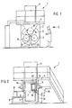
- a leak test machine (1) which consists of a frame (2) which is arranged in a stationary manner on the floor and which is approximately frame-shaped and is covered by a platform (3), the contours of which are shown in FIG. 3 are indicated by dash-dotted lines. Measuring devices and a vacuum pump device are arranged in a housing (4) on this platform in a manner not shown.
- a wheel star (5) is rotatably arranged in the frame (2) and is provided with three cylindrical drums (6), each offset by 120 ° to one another, which are arranged on the wheel star (5) so as to be rotatable about a common axis (7) are.
- a common axis (7) In the position (6 and 6 ') (Fig. 1) two of the cylindrical drums (6) are arranged in a common horizontal plane, which is selected such that barrels (9, 9') lying on a loading ramp (8) are also so are high that they can be easily inserted into and out of the cylindrical chambers can be removed again.
- Fig. 1 In the position (6 and 6 ') (Fig. 1) two of the cylindrical drums (6) are arranged in a common horizontal plane, which is selected such that barrels (9, 9') lying on a loading ramp (8) are also so are high that they can be easily inserted into and out of the cylindrical chambers can be removed again.
- the barrel (9) is inserted into the cylindrical chamber in the position (6 ') by a loading device, not explained in detail, for example with the aid of a pneumatic cylinder, in the direction of arrow (10), while at the same time the barrel (9 ') is moved out of the chamber (6) opposite the chamber (6') in the same horizontal plane in the sense of the arrow (11) with the aid of a pneumatic slide, also not shown.
- the third cylindrical drum is in position (6'') and is there to be described on both, or at least on one side closed, pressurized and sensed with the help of measuring instruments, not shown, whether there is test gas in the cylindrical drum.
- the wheel star (5) rotates in the frame (2) in the direction of the arrows (12), so that the cylindrical drum (6 '') in the test position is now in the position shown in FIG. 1 (6) arrives where the test object is unloaded.
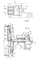
- the cover (14) that can be seen in FIG. 2 is provided with a peripheral edge (16) and with a seal (17) with which it is tightly attached to the flange (15) of the drum ( 6) can create when it has reached position (6 '').
- the cover (14) which is approximately circular, is fixedly arranged on an axis (18) which, via a pneumatic or hydraulic cylinder (19), moves in the direction of its axis (20) from the closed position (18) the position (18 ') can be shifted in which the cover (14), in its position (14'), is lifted off the flange (15) of the drum (6).
- the axis (18) is arranged in a longitudinally displaceable manner in a bearing (20) of a bearing block (21) which is firmly connected to the frame (2), as indicated in FIG. 4.
- the hydraulic or pneumatic cylinder (19) is also firmly screwed to the bearing block (21).
- the intermediate piece (24), which is rotatable relative to the piston rod (22) with the aid of a handle (25), has the task of being able to completely uncouple the hydraulic cylinder (19) from the ring (23) in order to be able to assemble or To be able to carry out disassembly.
- this is not important in the present invention.
- a ring bead (27) of a bellows-like cap (28) made of elastic plastic is fastened to the cover (14) with the aid of a fastening ring (26) and tightly clamped between the ring (26) and the cover (24).
- the cap (28) consists of a bellows-like outer edge (29) which integrally merges into a circular wall (28a) which is approximately parallel to the surface of the ring (26) and to the cover (14) and thus also runs parallel to the plane in which the end sealing flange (15) of the barrel (6) runs.
- a drum (9) is located within the drum (6) in position (6 '') of FIG. 1, which is indicated by dash-dotted lines.
- the essentially flat end wall (9a) of the barrel (9) lies in the middle in the closed position of the drum (6) (position 6 ′′) shown in FIG. 4 on the circular wall (28a).
- the wall (28a) also presses on nozzles (32) which protrude from the end wall region (9a) and which, for example, can be the filling nozzles of the barrel. In the open position of the cover (14 ') there is sufficient axial distance between the end edge (15) of the drum (6) and the wall (28a) of the support cap (28).
- the support cap (28) is provided in the middle with a cylindrical pin (33) projecting towards the bead (27), which protrudes somewhat beyond the plane of the bead (27) to the rear .
- This pin (33) serves as mechanical securing of the position of the support cap (28) on the cover (14).
- FIG. 5 and 6 also show that the inside of the drum (6) facing the side of the wall (28a) is provided with a plurality of individual knobs (34) protruding from the wall surface, which are semicircular in the exemplary embodiment and therefore the Have the shape of spherical sections.
- This design of the outside of the cap (28) ensures that the wall (28a) at no point can be so close to a counter wall, for example to the front wall (9a) of a barrel, that a pressure equalization between the outer areas of the membrane like wall (28a) and its interior is no longer possible.
- the negative pressure applied in position (6 '') inside the closed drum (6) ensures that the membrane-like wall (28a) the support cap (28) is pressed to the left against the end wall (9a) of the barrel (9) due to the pressure difference occurring in the space (30) and in the interior (35) of the drum (6).
- a similar cover cap (28) presses, which sits on the second mirror-symmetrically arranged cover (14), so that the position of the barrel within the drum (6) is secured during the leak test.
- the front wall (9a) of the barrel (9) tends to be deformed to the right with the same force as the membrane-like wall (28a) is deformed to the left.
- the hood-like support (28) is therefore suitable for avoiding excessive bulging of the end wall (9a) without the need for separate, complex devices for setting a counterforce. Nevertheless, the entire surface of the drum can be properly checked for leaks.
Landscapes
- Physics & Mathematics (AREA)
- General Physics & Mathematics (AREA)
- Examining Or Testing Airtightness (AREA)
Applications Claiming Priority (2)
| Application Number | Priority Date | Filing Date | Title |
|---|---|---|---|
| DE3940922 | 1989-12-12 | ||
| DE19893940922 DE3940922A1 (de) | 1989-12-12 | 1989-12-12 | Vorrichtung zur pruefung der dichtheit von behaeltern |
Publications (2)
| Publication Number | Publication Date |
|---|---|
| EP0432550A2 true EP0432550A2 (fr) | 1991-06-19 |
| EP0432550A3 EP0432550A3 (en) | 1992-09-02 |
Family
ID=6395262
Family Applications (1)
| Application Number | Title | Priority Date | Filing Date |
|---|---|---|---|
| EP19900122446 Withdrawn EP0432550A3 (en) | 1989-12-12 | 1990-11-24 | Device for testing containers for leaks |
Country Status (2)
| Country | Link |
|---|---|
| EP (1) | EP0432550A3 (fr) |
| DE (1) | DE3940922A1 (fr) |
Cited By (3)
| Publication number | Priority date | Publication date | Assignee | Title |
|---|---|---|---|---|
| EP0654656A1 (fr) * | 1993-11-18 | 1995-05-24 | Martin Lehmann | Procédé d'essai d'étanchéité |
| AU699979B2 (en) * | 1993-11-18 | 1998-12-17 | Martin Lehmann | Method of leak testing |
| CN118896741A (zh) * | 2024-10-08 | 2024-11-05 | 山东百帝新材料有限公司 | 一种化工物料存储运输专用桶密封性能检测设备 |
Families Citing this family (1)
| Publication number | Priority date | Publication date | Assignee | Title |
|---|---|---|---|---|
| DE19846800A1 (de) * | 1998-10-10 | 2000-04-13 | Leybold Vakuum Gmbh | Folien-Lecksucher |
Family Cites Families (3)
| Publication number | Priority date | Publication date | Assignee | Title |
|---|---|---|---|---|
| NL91317C (fr) * | 1958-08-07 | 1959-06-15 | ||
| US3813923A (en) * | 1972-05-23 | 1974-06-04 | Universal Sales Eng Inc | Adaptive fixture for leak testing of containers |
| US4905501A (en) * | 1987-12-24 | 1990-03-06 | Kabushiki Kaisha Nippon Automation | Jig for leak check |
-
1989
- 1989-12-12 DE DE19893940922 patent/DE3940922A1/de active Granted
-
1990
- 1990-11-24 EP EP19900122446 patent/EP0432550A3/de not_active Withdrawn
Cited By (5)
| Publication number | Priority date | Publication date | Assignee | Title |
|---|---|---|---|---|
| US5497654A (en) * | 1989-01-27 | 1996-03-12 | Lehmann; Martin | Method and apparatus for leak testing a container |
| EP0654656A1 (fr) * | 1993-11-18 | 1995-05-24 | Martin Lehmann | Procédé d'essai d'étanchéité |
| AU685172B2 (en) * | 1993-11-18 | 1998-01-15 | Martin Lehmann | Method of leak testing |
| AU699979B2 (en) * | 1993-11-18 | 1998-12-17 | Martin Lehmann | Method of leak testing |
| CN118896741A (zh) * | 2024-10-08 | 2024-11-05 | 山东百帝新材料有限公司 | 一种化工物料存储运输专用桶密封性能检测设备 |
Also Published As
| Publication number | Publication date |
|---|---|
| DE3940922A1 (de) | 1991-06-13 |
| EP0432550A3 (en) | 1992-09-02 |
| DE3940922C2 (fr) | 1993-01-21 |
Similar Documents
| Publication | Publication Date | Title |
|---|---|---|
| DE68904414T2 (de) | Behaelter. | |
| DE2930963A1 (de) | Verpackungsvorrichtung | |
| DE2345731C3 (de) | Vorrichtung zur Prüfung von Hohlkörpern, insbesondere Glasflaschen | |
| DE1573478A1 (de) | Verfahren zur serienweisen Pruefung von Hohlkoerpern auf Dichtheit und Pruefeinrichtung zur automatischen Durchfuehrung des Verfahrens | |
| DE1907003A1 (de) | Verfahren und Vorrichtung zum Pruefen von Deckeln auf Undichtigkeiten | |
| DE2404197A1 (de) | Verfahren zur befestigung von praeparierten deckeln auf behaeltern und vorrichtung zur ausuebung des verfahrens | |
| DE3940922C2 (fr) | ||
| DE2422275C3 (de) | Zigare ttenprüfvorrichtung | |
| EP0017147A1 (fr) | Récipient sous pression à deux compartiments pour distribuer un produit | |
| DE2928296C2 (fr) | ||
| DE2612952C2 (de) | Vorrichtung zum Ergreifen einer verformbaren Platte mittels eines Saugnapfes | |
| DE2818178A1 (de) | Dichtungseinrichtung an der einlass- oder auslassoeffnung eines unterdruck- oder ueberdruckbehaelters fuer die behandlung textiler warenbahnen | |
| DE3044550A1 (de) | Verfahren und vorrichtung zur dichtheitskontrolle von einwegspritzen | |
| DE2634444A1 (de) | Vorrichtung zum runderneuern von luftreifen | |
| DE2711649B2 (de) | Verfahren und Vorrichtung zur Herstellung von kegelförmigen Tuben | |
| DE2659787A1 (de) | Vorrichtung zum gasdichten befestigen eines folienbehaeltnisses | |
| DE2728838A1 (de) | Verfahren und vorrichtung zur integralen lecksuche | |
| DE3423307A1 (de) | Reifenfuelleinrichtung | |
| DE3046850C2 (fr) | ||
| DE69000599T2 (de) | Fluessigkeitsspeicher. | |
| DE8135872U1 (de) | Vorrichtung zur Abgabe eines pastoesen Mittels insbesondere eines Dichtungsmittels | |
| DE69507384T2 (de) | Vorrichtung zum Zuführen von Gruppen von Tabakartikeln zu einer Umwickelstrasse | |
| EP2205347B1 (fr) | Système de sas et procédé pour ouvrir un système de sas | |
| DE2727135C3 (de) | Dichtungseinrichtung am EinlaB oder AuslaB eines Hochdruckdämpfers | |
| DE1997665U (de) | Vorrichtung zur herstellung von verpackungsbehaeltern |
Legal Events
| Date | Code | Title | Description |
|---|---|---|---|
| PUAI | Public reference made under article 153(3) epc to a published international application that has entered the european phase |
Free format text: ORIGINAL CODE: 0009012 |
|
| AK | Designated contracting states |
Kind code of ref document: A2 Designated state(s): DE FR GB IT NL SE |
|
| PUAL | Search report despatched |
Free format text: ORIGINAL CODE: 0009013 |
|
| AK | Designated contracting states |
Kind code of ref document: A3 Designated state(s): DE FR GB IT NL SE |
|
| 17P | Request for examination filed |
Effective date: 19930217 |
|
| 17Q | First examination report despatched |
Effective date: 19930723 |
|
| STAA | Information on the status of an ep patent application or granted ep patent |
Free format text: STATUS: THE APPLICATION IS DEEMED TO BE WITHDRAWN |
|
| 18D | Application deemed to be withdrawn |
Effective date: 19931203 |