EP0432552A1 - Vanne sanitaire - Google Patents
Vanne sanitaire Download PDFInfo
- Publication number
- EP0432552A1 EP0432552A1 EP90122491A EP90122491A EP0432552A1 EP 0432552 A1 EP0432552 A1 EP 0432552A1 EP 90122491 A EP90122491 A EP 90122491A EP 90122491 A EP90122491 A EP 90122491A EP 0432552 A1 EP0432552 A1 EP 0432552A1
- Authority
- EP
- European Patent Office
- Prior art keywords
- valve
- closure
- valve seat
- auxiliary valve
- outlet
- Prior art date
- Legal status (The legal status is an assumption and is not a legal conclusion. Google has not performed a legal analysis and makes no representation as to the accuracy of the status listed.)
- Granted
Links
- XLYOFNOQVPJJNP-UHFFFAOYSA-N water Substances O XLYOFNOQVPJJNP-UHFFFAOYSA-N 0.000 claims abstract description 60
- 230000005540 biological transmission Effects 0.000 claims description 14
- 239000012528 membrane Substances 0.000 claims description 12
- 230000000903 blocking effect Effects 0.000 claims 2
- 238000006073 displacement reaction Methods 0.000 abstract description 2
- 238000007789 sealing Methods 0.000 description 11
- 230000006835 compression Effects 0.000 description 10
- 238000007906 compression Methods 0.000 description 10
- 238000001514 detection method Methods 0.000 description 4
- 239000013013 elastic material Substances 0.000 description 3
- 230000001105 regulatory effect Effects 0.000 description 2
- 230000000284 resting effect Effects 0.000 description 2
- 230000007704 transition Effects 0.000 description 2
- 230000007423 decrease Effects 0.000 description 1
- 230000001419 dependent effect Effects 0.000 description 1
- 239000012530 fluid Substances 0.000 description 1
- 230000002093 peripheral effect Effects 0.000 description 1
Images


Classifications
-
- F—MECHANICAL ENGINEERING; LIGHTING; HEATING; WEAPONS; BLASTING
- F16—ENGINEERING ELEMENTS AND UNITS; GENERAL MEASURES FOR PRODUCING AND MAINTAINING EFFECTIVE FUNCTIONING OF MACHINES OR INSTALLATIONS; THERMAL INSULATION IN GENERAL
- F16K—VALVES; TAPS; COCKS; ACTUATING-FLOATS; DEVICES FOR VENTING OR AERATING
- F16K11/00—Multiple-way valves, e.g. mixing valves; Pipe fittings incorporating such valves
- F16K11/10—Multiple-way valves, e.g. mixing valves; Pipe fittings incorporating such valves with two or more closure members not moving as a unit
- F16K11/14—Multiple-way valves, e.g. mixing valves; Pipe fittings incorporating such valves with two or more closure members not moving as a unit operated by one actuating member, e.g. a handle
- F16K11/18—Multiple-way valves, e.g. mixing valves; Pipe fittings incorporating such valves with two or more closure members not moving as a unit operated by one actuating member, e.g. a handle with separate operating movements for separate closure members
-
- F—MECHANICAL ENGINEERING; LIGHTING; HEATING; WEAPONS; BLASTING
- F16—ENGINEERING ELEMENTS AND UNITS; GENERAL MEASURES FOR PRODUCING AND MAINTAINING EFFECTIVE FUNCTIONING OF MACHINES OR INSTALLATIONS; THERMAL INSULATION IN GENERAL
- F16K—VALVES; TAPS; COCKS; ACTUATING-FLOATS; DEVICES FOR VENTING OR AERATING
- F16K31/00—Actuating devices; Operating means; Releasing devices
- F16K31/12—Actuating devices; Operating means; Releasing devices actuated by fluid
- F16K31/36—Actuating devices; Operating means; Releasing devices actuated by fluid in which fluid from the circuit is constantly supplied to the fluid motor
- F16K31/38—Actuating devices; Operating means; Releasing devices actuated by fluid in which fluid from the circuit is constantly supplied to the fluid motor in which the fluid works directly on both sides of the fluid motor, one side being connected by means of a restricted passage and the motor being actuated by operating a discharge from that side
- F16K31/385—Actuating devices; Operating means; Releasing devices actuated by fluid in which fluid from the circuit is constantly supplied to the fluid motor in which the fluid works directly on both sides of the fluid motor, one side being connected by means of a restricted passage and the motor being actuated by operating a discharge from that side the fluid acting on a diaphragm
- F16K31/3855—Actuating devices; Operating means; Releasing devices actuated by fluid in which fluid from the circuit is constantly supplied to the fluid motor in which the fluid works directly on both sides of the fluid motor, one side being connected by means of a restricted passage and the motor being actuated by operating a discharge from that side the fluid acting on a diaphragm the discharge being effected through the diaphragm and being blockable by a mechanically-actuated member making contact with the diaphragm
-
- Y—GENERAL TAGGING OF NEW TECHNOLOGICAL DEVELOPMENTS; GENERAL TAGGING OF CROSS-SECTIONAL TECHNOLOGIES SPANNING OVER SEVERAL SECTIONS OF THE IPC; TECHNICAL SUBJECTS COVERED BY FORMER USPC CROSS-REFERENCE ART COLLECTIONS [XRACs] AND DIGESTS
- Y10—TECHNICAL SUBJECTS COVERED BY FORMER USPC
- Y10T—TECHNICAL SUBJECTS COVERED BY FORMER US CLASSIFICATION
- Y10T137/00—Fluid handling
- Y10T137/8593—Systems
- Y10T137/87153—Plural noncommunicating flow paths
- Y10T137/87161—With common valve operator
-
- Y—GENERAL TAGGING OF NEW TECHNOLOGICAL DEVELOPMENTS; GENERAL TAGGING OF CROSS-SECTIONAL TECHNOLOGIES SPANNING OVER SEVERAL SECTIONS OF THE IPC; TECHNICAL SUBJECTS COVERED BY FORMER USPC CROSS-REFERENCE ART COLLECTIONS [XRACs] AND DIGESTS
- Y10—TECHNICAL SUBJECTS COVERED BY FORMER USPC
- Y10T—TECHNICAL SUBJECTS COVERED BY FORMER US CLASSIFICATION
- Y10T137/00—Fluid handling
- Y10T137/8593—Systems
- Y10T137/87571—Multiple inlet with single outlet
- Y10T137/87676—With flow control
- Y10T137/87684—Valve in each inlet
- Y10T137/87692—With common valve operator
Definitions
- the present invention relates to a sanitary fitting according to the preamble of claim 1.
- Faucets of this type are commercially available. These usually have a hydraulically actuated shut-off valve for the hot and cold water, each with an auxiliary valve integrated therein, which is opened by means of an electromagnet to open the shut-off valve. To interrupt the water flow, the electromagnets are switched off, causing the auxiliary valves and the shut-off valves controlled by them to close.
- the shut-off valves have a membrane-shaped closure part which interacts with a stationary, annular valve seat. Around the valve seat runs an annular channel open towards the closure part, which is connected to a relevant inlet for the hot or cold water. An outlet opening is surrounded by the valve seat, which opens into a mixing valve via a line.
- the mixing valve adjusts the amount of water flowing through each shut-off valve in order to regulate the temperature of the mixed water leaving the fitting through an outlet.
- a pilot control space is provided on the side opposite the valve seat, which is flow-connected to the ring channel via a small passage in the closure part.
- the closure part has a control passage which is delimited by an auxiliary valve on the pilot control chamber side.
- the flow cross section of this Control passage is larger than the flow cross-section of the passage connecting the pilot chamber with the ring channel.
- An auxiliary valve seat which surrounds the control passage and is formed on the closure part interacts with a plunger anchor-shaped closure element arranged in the pilot control chamber.
- the closing element When the auxiliary and shut-off valve is closed, the closing element is held in the rest position by a pressure spring provided in the pilot control chamber and resting on the auxiliary valve seat.
- the pressure inside the pilot control chamber due to the connection between the ring channel and the pilot control chamber through the passage corresponds to the pressure of the water supplied through the relevant inlet.
- the closure part is pressed onto the valve seat.
- the closing element is pulled from the rest position into an open position by exciting the electromagnet, in which it releases the control passage.
- the pilot control chamber is thereby connected to the outlet, which means that the pressure in the pilot control chamber drops.
- the closure part is lifted off the valve seat and the water flow from the ring channel is released into the outlet opening.
- the auxiliary valve remains fully open to ensure that the pressure on the pilot control chamber side is always lower than the pressure on the other side of the closure part in order to keep the shut-off valve securely completely open.
- the electromagnet is de-energized, so that the closure element comes under the force of the compression spring to the auxiliary valve seat position, which has the consequence that the pressure in the pilot room increases.
- the closure part is moved towards the valve seat until it bears against it and blocks the water flow.
- the compression spring always keeps the closure element in contact with the valve seat. This fitting is complex to construct.
- the closure element can be brought into a limiting position between the rest position and the open position by means of a drive arrangement and can be held there.
- the auxiliary valve automatically regulates the pressure in the control circuit in such a way that the valve only allows an amount of water corresponding to the limiting position to flow through.
- a permanently pressurized dynamic seal is prevented for a transmission element that is operatively connected to the closure element.
- a particularly preferred and extremely simple fitting is specified in claim 8.
- a common drive arrangement for both valves requires extremely little energy.
- both the temperature of the mixed water and the outflowing amount of mixed water can be set by means of a single drive arrangement in a mixing fitting.
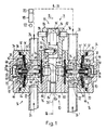
- FIGS 1 to 3 show part of an electrically controlled sanitary mixer tap. Such faucets are commonly used as sink faucets.
- the valve has a central drive block 10 and two identically designed valve blocks 14 and 16 which are laterally attached to it by screws 12.
- a hydraulically actuated valve 18, 20 is provided in each valve block 14, 16.
- the valve 18 is connected in terms of flow via an inlet 22 in the valve block 14 to an inflow line 24 for cold water, while the other valve 20 is connected to an inflow line 24 'for hot water through a corresponding inlet 22 ′ in the valve block 16.
- the two valves 18, 20 are connected by means of lines 26 to a common water outlet head 28 (only schematically indicated) (FIG. 1).
- Each valve block 14, 16 has a stepped recess 32 which is essentially rotationally symmetrical with respect to the axis 30 of the two valves 18, 20 and which is closed to the outside in a watertight manner by a hat-shaped cover 34 engaging in the recess 32.
- the corresponding annular seal arranged between the valve block 14, 16 and cover 34 is designated by 36.
- a membrane-shaped closure part 38 which spans this and which is made of rubber-elastic Material exists and is clamped in the circumferential area between a shoulder 32 'in the recess 32 and the end 34' of the cover 34 which engages in the recess 32.
- the closure part 38 and the cover 34 delimit a pilot control chamber 40.
- annular valve seat 42 cooperating with it is provided, around which a valve seat 42 connected to the relevant inlet 22 and 22 ′ and against it Closure part 38 open annular channel 44 extends.
- a small passage 46 is attached in the closure part 38, which connects the pilot control chamber 40 to the ring channel 42 and thus to the inlet 22, 22 '.
- the part of the recess 32 which follows the valve seat 42, seen from the outside, towards the inside and is surrounded by the valve seat 42, forms an outlet 48 or 48 ', which opens into the corresponding lines 26 leading approximately at right angles to the axis 30.
- the recess 32 is delimited by a disk-shaped sealing membrane 50 made of rubber-elastic material, which is clamped in the peripheral area between the drive block 10 and each corresponding valve block 14, 16.
- auxiliary valve 52, 54 assigned to the relevant valve 18, 20 is provided in each pilot control chamber 40.
- Each of these auxiliary valves 52, 54 has an auxiliary valve seat 56 and a closing element 58 which interacts with it.
- the auxiliary valve seat 56 is formed on a hollow cylindrical sleeve 60 which is approximately concentric with the axis 30 and which is inserted into an annular stiffening member 62 which penetrates the membrane-shaped closure part 38 in a central opening 38 'and on this through in Flanks 62 'protruding outward in the radial direction.
- the pilot control chamber 40 connected to the inlet 22, 22' through the passage 46, the auxiliary valve 52, 54 and the control passage 60 'connected to the outlet 48, 48' form a hydraulic control circuit for the hydraulically actuable valves 18, 20.
- An actuating pin 64 through which the closure element 58 is stuck in the pilot control chamber 40, runs through the sleeve 60.
- This has an O-ring 66 which interacts with the auxiliary valve seat 56, which sits on the actuating pin 64 and is encompassed by a hat-shaped holding part 68 fastened thereon along the circumference and on the side facing away from the auxiliary valve seat 56.
- One end of a compression spring 70 is supported on the holding part 68, which abuts the cover 34 at the other end and presses the closure element 58 against the auxiliary valve seat 56.
- the compression spring 70 is part of a drive arrangement 71.
- the cross section of the actuating pin 64 is smaller than the inside width of the sleeve 60, so that between the sleeve 60 and the actuating pin 64 there is always a control passage 60 ', the cross-sectional area of which is larger than the passage 46, which connects the ring channel 44 to the pilot chamber 40.
- the actuating pin 64 has longitudinal grooves 72 which, after the closure element 58 has been lifted off from the auxiliary valve seat 52, 54, additionally increase the flow cross section between the sleeve 60 and the actuating pin 64.
- the pilot control chamber 40 is in fluid communication with the outlet 48 or 48 ′. This connection is interrupted when the O-ring 66 of the closure element 58 rests on the auxiliary valve seat 56.
- a plate-shaped transmission element 74 which encompasses the end region of the actuating pin 64 and is closed against the sealing membrane 50 and which, when the sealing membrane 50 is deflected, in the direction towards the valve 18, 20 Deflection transmits to the actuating pin 64 and the auxiliary valve 52, 54, without impermissibly large surface pressures occurring in the sealing membrane 50 made of rubber-elastic material.
- the closure part 38 is shown resting against the valve seat 42 and the closure element 58 against the auxiliary valve seat 58.
- the valves 18, 20 and auxiliary valve 52, 54 are thus closed.
- the closure element 58 is in its rest position.
- the drive block 10 has two stepped, cylindrical through openings 76, 78 which intersect at right angles, the through opening 76 running concentrically to the axis 30 being delimited by the two sealing membranes 50.
- two sliding shoes 80 are guided so as to be displaceable in the direction of the axis 30, each of which abuts a sealing membrane 50 on one end and projects into the other through opening 78 on the other.
- the two sliding shoes 80 are convexly shaped, on the one hand to uniformly stress them when the sealing membrane 50 is bent out, and on the other hand to enable problem-free sliding on a control pin 82 engaging in the through opening 78.
- the axis 78 'of the rotationally symmetrical, stepped through opening 78 is perpendicular to the axis 30 and the control pin 82 is rotatable about this axis 78' and is displaceable in the direction of this axis 78 '.
- a sliding sleeve 86 is guided so as to be displaceable in the direction of the axis 78 '.
- the control pin 82 guided through the sliding sleeve 86 is mounted on the latter so as to be displaceable in the direction of the axis 78 ′, but can be rotated about 180 ° about the axis 78.
- the sliding sleeve 86 has a slot 88 which extends in the circumferential direction and extends over approximately 180 ° and in which a bolt 90 which is anchored in the control pin 82 and extends in the radial direction is guided.
- the control pin 82 engages in a further part 84 'arranged below the sliding shoes 80 with the smallest clear width of the passage opening 78 and is rotatably guided therein and displaceable in the direction of the axis 78' .
- the central region 82' of the control pin 82 is not rotationally symmetrical to the axis 78 '.
- This middle part 82 ' has a cylindrical region 82''but eccentric to the axis 78' and a transition region 82 '''which connects the part 82''to the end region 82a in the form of an oblique cone.
- the cylindrical, eccentric part 82 ′′ is designed with respect to the smaller end region 82a in such a way that they have a common surface line that is straight and runs parallel to the axis 78 '. This surface line is designated 92 in FIGS. 4 to 6.
- the surface of the control pin 82 in the central region 82 ′ and end region 82a forms a control surface for the sliding shoes 80.
- control pin 82 has a head 94, on which engagement surfaces 94 'are formed in order to turn the control pin 82 into the desired position by means of a corresponding operating handle (not shown).
- the sliding sleeve 86 In the sliding sleeve 86 are two diametrically opposite driver pins 96 which project in the radial direction beyond the sliding sleeve 86.
- the sliding sleeve 86 is encompassed in its upper end region by a fork-shaped arm 98 of a two-armed drive lever 100.
- the forked arm 98 In the free end regions, the forked arm 98 has slots 98 ′ which are penetrated by the driving bolts 96.
- the drive lever 100 is pivotably mounted on a shaft 102 running at right angles to the axis 78 'and has on its other arm 104 a toothed segment 106 which is concentric with the shaft 102 and which meshes with a pinion 110 driven by a drive motor 108.
- the drive lever 100 can be pivoted by means of the drive motor 108 from a rest position 100 'shown in broken lines to a working position shown in dashed lines and back again.
- the transmission sleeve 74 moves together with the control pin 82, in the direction of the axis 78 ', from the corresponding rest position, also indicated by dash-dotted lines, into a corresponding working position indicated in solid lines and back again.
- the sliding shoes 80, the control pin 82, the sliding sleeve 86, the drive lever 100, the pinion 110 and the drive motor 108 form a drive part 111 of the drive arrangement 71.
- FIGS. 4 to 6 show part of the drive block 10 in three different positions of the control pin 82.
- the control pin 82 In the position shown in FIG. 4, the control pin 82 is in its upper rest position, indicated by dash-dotted lines in FIG. 3.
- the sliding shoes 80 lie against the end region 82a of the control pin 82 which is concentric with the axis 78 '. Both sealing membranes 50 are not bent out.
- the valves 18, 20 and auxiliary valves 52, 54 are closed, as shown in FIGS. 1 and 2.
- the control pin 82 is in its lower end position shown in solid lines in FIG. 3.
- the sliding shoes 80 rest on the cylindrical part 82 ′′ eccentric to the axis 78 '. Since the surface line 92 is located in a plane 112 perpendicular to the axis 30, in which the axis 78 'of the control pin 82 is located, the two sliding shoes 80 are further away from the plane 112 in the direction of the axis 30 than in FIG Fig. 4.
- the sealing membranes 50 are bent out by the same amount.
- control pin 82 is also in its lower working position.
- the surface line 92 is, however, rotated out of the plane 112 in the counterclockwise direction by the angle ⁇ . This now has the consequence that the sliding shoe 80 shown on the left in FIG. 6 is in one Intermediate position between the two positions shown in Figures 4 and 5.
- the sliding shoe 80 shown on the right in FIG. 6, however, is further raised in the direction of the axis 30 compared to FIG. 5.
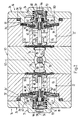
- FIG. 7 shows the valve in the same section as FIG. 2 but with the control pin 82 in a position according to FIG. 6.
- the sliding block 80 shown on the left in FIGS. 6 and 7 is slightly raised by turning the control pin 82, whereas the one shown on the right Sliding shoe 80 is deflected more in the direction of the axis 30.
- the stroke in the direction of the axis 30 of the sliding shoes 80 is transmitted through the sealing membranes 50 to the transmission elements 74 and through this via the actuating pin 64 to the relevant closure element 58, so that the two closure elements 58, as shown in FIG two different limit positions 58 '.
- the closure element 58 is thus raised in relation to the rest position, in which the closure element 58 rests on the auxiliary valve seat 56 in the closed valve 18 or 20, in accordance with the stroke and the rotational position of the control pin 82.
- a gap designated 114 is shown, whereby the pilot chamber 40 is connected to the relevant outlet 48 or 48 '.
- the flow cross-section between the O-rings 66 and the corresponding auxiliary valve seats 56 corresponds approximately to the cross-section of the passages 46 which connect the pilot control chambers 40 to the corresponding inlets 22 and 22 '.
- the two closure parts 38 of the valves 18, 20 are lifted off the corresponding valve seats 42 and release an outflow gap designated 116 and 116 ', through which the inlets 22, 22' with the Outlets 48, 48 'are connected.
- the outflow gap 116 of the valve 18 assigned to the cold water is narrower than the outflow gap 116 'of the valve 20 assigned to the hot water.
- the two valves 18, 20 are thus outward in accordance with the displacement of the two sliding shoes 80 in the direction of the axis 30 and thus in accordance with the limiting position 58 'of the closure elements 58 partially opened.
- the fitting shown in FIGS. 1 to 7 has an electronic control 118, schematically shown in FIG. 1, with a sensor 120.
- the controller 118 is powered by a battery 122 and controls the drive motor 108 shown in FIG. 3.
- the sensor 120 detects when there are hands to be washed in the area of the washbasin or the water outlet head 118.
- the fitting described above works as follows. If there are no hands to be washed in the detection area of the sensor 120, the drive lever 100 is in the rest position 110 'indicated by dash-dotted lines in FIG. 3.
- the control pin 82 is raised to the rest position shown in FIGS. 1 to 4.
- the sliding shoes 80 bear against the end region 82a of the control pin 82.
- the auxiliary valves 52, 54 and valves 18, 20 are closed.
- the closure elements 58 are in their rest position.
- the pressure in the pilot control chambers 40 corresponds to the pressure of the water in the relevant inlet 22 or 22 'as a result of the connection through the passage 46 to the annular channel 44.
- the closure part 38 is pressed against the valve seat 42 with a force that is proportional to the difference in the pressure in the pilot control chamber 40 and outlet 48, 48 ′ as well as to the difference in the pressurized surfaces of the closure part 38 in the region of the annular channel 44 and the pilot control chamber 40.
- this force which is proportional to the water pressure
- the compression spring 70 which also acts on the closure part 38 via the closure element 58.
- This compression spring 70 thus presses the closure element 58 against the auxiliary valve seat 56, which is additionally pressed against the auxiliary valve seat 56 with a force which is proportional to the area delimited by the auxiliary valve seat 56 and the difference in pressure in the pilot control chamber 40 and outlet 48, 48 ' .
- the free end of the actuating pin 64 is slightly spaced from the transmission sleeve 74 to ensure that the O-ring 66 rests on the auxiliary valve seat 56 in the rest position of the closure element 58.
- the outlets 48, 48 ' are connected to the environment via the lines 26 and the water outlet head 28, so that the outlet-side pressure corresponds to the ambient pressure when the valves 18, 20 are closed.
- the electronic control 118 controls the drive motor 108 until the drive lever 110 is pivoted into the working position shown in solid lines in FIG.
- the control pin 82 is brought into the lower end position shown in solid lines in FIGS. 3, 5 and 6.
- the closure elements 58 corresponding to the rotational position ⁇ of the control pin 82 the rest position can be raised to the limit position 58 '.
- the two auxiliary valves 52, 54 open, which has the consequence that the pilot control chambers 40 are now in flow communication with the outlets 22, 22 '.
- the pressure in the pilot control chamber 40 and on the other side of the closure part 38 is equalized, so that the closure part 38 is self-regulating while keeping a small gap 114 in one of the Closure element 58 is held predetermined position.
- the amount of water flowing through the outflow gaps 116, 116 'per unit of time is thus predetermined by the limiting position 58' of the closure element 58.
- the cold or hot water now flowing through the valves 18, 20 is fed through the lines 26 to the common water outlet head 28, where the hot and cold water mix and flows out of the water outlet head 28 as mixed water.
- the rotational position ⁇ of the control pin 82 thus roughly determines the amount of cold water or hot water flowing through each valve 18, 20 per unit of time, as a result of which the temperature of the mixed water is determined.
- the mixed water temperature can thus be adjusted by turning the control pin 82 accordingly.
- the controller 118 feeds the drive motor 108 in such a way that it pivots the drive lever 100 again into the rest position 100 'shown in dash-dotted lines in FIG. 3.
- the control pin 82 is pulled into the upper end position, with the result that the lower end region 82a comes to lie in the region of the sliding shoes 80.
- the closure elements 58 are therefore no longer held in their limiting position 58 ′ by the control pin 82 against the force of the compression spring 70, which has the consequence that the closure elements 58 come into contact with the auxiliary valve seats 56 due to the force of the compression springs 70.
- the auxiliary valves 52, 54 are closed.
- both valves 18, 20 are opened to the same extent, which means that the corresponding valves 18, 20 can flow.
- the temperature of the mixed water then corresponds to the mean value between the temperature of the cold and hot water.
- the control pin 82 is pivoted by the angle ⁇ , as shown in FIGS. 6 and 7, the valve 18 for cold water less, but the valve 20 for hot water opened more, which means that the temperature of the mixed water is higher.
- the total amount of water flowing out of the mixed water per unit of time remains approximately the same regardless of the rotational position of the control pin 82.
- the desired mixed water temperature is thus set by pivoting the control pin 82.
- Mixed water of the appropriate temperature then flows out of the fitting as long as there are hands to be washed in the detection area of the sensor 120.
- the control pin 82 can be connected, for example, to a rotary knob, to select the temperature of the mixed water individually by rotating the control pin 82.
- the electronic control 118 in such a way that the drive lever 100 is pivoted into an intermediate position and held there when pivoting out of the rest position shown in dash-dot lines in FIG. 3 in the direction opposite the working position shown with solid lines. The result of this is that the sliding shoes 80 come into contact with the control pin 82 in the transition region 82 ′′ ′′. The amount of mixed water released per unit of time is thus reduced, but the mixed water temperature still corresponds to the relevant rotational position of the control pin 82.
- valve it is also conceivable to design the valve as a one-hand lever mixer.
- the control pin 82 is connected to the transmission sleeve 74 in a rotationally fixed and stroke-resistant manner.
- the drive lever 100 is then replaced by an actuating lever which is rotatably mounted on the drive block 110 about the axis 78 ′ and is pivotable about an axis corresponding to the shaft 102.
- the desired temperature can then be set by rotating the actuating lever about the shaft 78 'and the desired amount of water can be set by pivoting about the horizontal axis.
- a fitting can of course only have a single valve 18 or 20.
- the amount of water flowing through the valve can be regulated according to the invention.
- closure element in the form of a piston.
Landscapes
- Engineering & Computer Science (AREA)
- General Engineering & Computer Science (AREA)
- Mechanical Engineering (AREA)
- Multiple-Way Valves (AREA)
- Mechanically-Actuated Valves (AREA)
- Temperature-Responsive Valves (AREA)
- Infusion, Injection, And Reservoir Apparatuses (AREA)
- Orthopedics, Nursing, And Contraception (AREA)
Applications Claiming Priority (2)
| Application Number | Priority Date | Filing Date | Title |
|---|---|---|---|
| CH4482/89A CH680527A5 (fr) | 1989-12-13 | 1989-12-13 | |
| CH4482/89 | 1989-12-13 |
Publications (2)
| Publication Number | Publication Date |
|---|---|
| EP0432552A1 true EP0432552A1 (fr) | 1991-06-19 |
| EP0432552B1 EP0432552B1 (fr) | 1994-08-24 |
Family
ID=4276927
Family Applications (1)
| Application Number | Title | Priority Date | Filing Date |
|---|---|---|---|
| EP90122491A Expired - Lifetime EP0432552B1 (fr) | 1989-12-13 | 1990-11-26 | Vanne sanitaire |
Country Status (7)
| Country | Link |
|---|---|
| US (1) | US5095944A (fr) |
| EP (1) | EP0432552B1 (fr) |
| AT (1) | ATE110453T1 (fr) |
| CA (1) | CA2030746C (fr) |
| CH (1) | CH680527A5 (fr) |
| DE (1) | DE59006899D1 (fr) |
| ES (1) | ES2058732T3 (fr) |
Cited By (2)
| Publication number | Priority date | Publication date | Assignee | Title |
|---|---|---|---|---|
| EP1538378A1 (fr) | 2003-12-03 | 2005-06-08 | Sanimatic Ag | Actionneur électromagnétique |
| DE102012221051A1 (de) * | 2012-11-19 | 2014-05-22 | Hansgrohe Se | Ventileinrichtung für ein Sanitärventil |
Families Citing this family (13)
| Publication number | Priority date | Publication date | Assignee | Title |
|---|---|---|---|---|
| GB9806991D0 (en) * | 1998-04-02 | 1998-06-03 | Mangar International Ltd | Low pressure pneumatic control valve systems |
| US6899118B1 (en) | 2000-08-31 | 2005-05-31 | Emerson Electric Co. | Single coil two operator controller |
| US6508272B1 (en) | 2000-11-20 | 2003-01-21 | Arichell Technologies, Inc. | Device and method for operating at least two valves |
| US6659373B1 (en) * | 2001-05-30 | 2003-12-09 | L. R. Nelson | One touch actuated valve |
| US7185243B1 (en) * | 2001-06-04 | 2007-02-27 | Lsi Logic Corporation | Testing implementation suitable for built-in self-repair (BISR) memories |
| CA2469182C (fr) * | 2001-12-04 | 2014-06-03 | Arichell Technologies, Inc. | Robinets electroniques concus pour un fonctionnement a long terme |
| WO2004005628A2 (fr) * | 2002-06-24 | 2004-01-15 | Arichell Technologies, Inc. | Systemes de distribution d'eau automatises a commande asservie |
| US20120298222A1 (en) * | 2009-10-29 | 2012-11-29 | S.P.C. Tech Ltd. | Flow control valve |
| US9695579B2 (en) | 2011-03-15 | 2017-07-04 | Sloan Valve Company | Automatic faucets |
| WO2012125213A1 (fr) | 2011-03-15 | 2012-09-20 | Sloan Valve Company | Robinets automatiques |
| DE102016001975A1 (de) * | 2016-02-22 | 2017-08-24 | Neoperl Gmbh | Ventilbetätigungsvorrichtung |
| US11512655B2 (en) * | 2020-09-16 | 2022-11-29 | Tlx Technologies, Llc | Fuel tank isolation valve |
| US11841085B1 (en) * | 2021-02-11 | 2023-12-12 | United States Of America As Represented By The Secretary Of The Air Force | Piston actuated cartridge valve |
Citations (3)
| Publication number | Priority date | Publication date | Assignee | Title |
|---|---|---|---|---|
| US2616710A (en) * | 1947-09-26 | 1952-11-04 | Rollin W Woodruff | Mixing faucet |
| FR2334037A1 (fr) * | 1975-12-04 | 1977-07-01 | Deles Andre | Vanne de commande d'ouverture et de fermeture d'un circuit fluide sous pression |
| DE2902410A1 (de) * | 1979-01-23 | 1980-07-31 | Hansa Metallwerke Ag | Drucktastenventil |
Family Cites Families (18)
| Publication number | Priority date | Publication date | Assignee | Title |
|---|---|---|---|---|
| US2301439A (en) * | 1940-04-12 | 1942-11-10 | Alfred M Moen | Multivalved faucet |
| US2346904A (en) * | 1941-06-19 | 1944-04-18 | Crane Co | Valve |
| US2496553A (en) * | 1942-11-18 | 1950-02-07 | Littlefield Edgar Earle | Valve mechanism |
| US3178151A (en) * | 1963-01-23 | 1965-04-13 | Marquardt Corp | Linear displacement electromagnetic actuator |
| US3181790A (en) * | 1963-07-12 | 1965-05-04 | Maytag Co | Fluid flow control device |
| US3306570A (en) * | 1963-10-07 | 1967-02-28 | R D Cooksley Mfg Company | Valves and valve structure |
| US3472277A (en) * | 1967-05-24 | 1969-10-14 | North American Rockwell | Magnetically interlinked multi-valve assembly |
| DE1775108A1 (de) * | 1967-07-08 | 1971-07-08 | Candy Spa | Regel- und Steuervorrichtung,insbesondere fuer Waschmaschinen,Geschirrspuelmaschinen od. dgl. |
| US3550901A (en) * | 1968-03-27 | 1970-12-29 | Robertshaw Controls Co | Valve construction with modulating diaphragm construction |
| US3667722A (en) * | 1970-10-22 | 1972-06-06 | Ite Imperial Corp | Proportional valve |
| US3818928A (en) * | 1972-02-03 | 1974-06-25 | Cvc Co | Hydropneumatic capacitor |
| US3977436A (en) * | 1972-11-02 | 1976-08-31 | Fluid Devices Limited | Bi-stable valve apparatus |
| FR2225675A1 (fr) * | 1973-04-12 | 1974-11-08 | Schwarzkopf Imre | |
| FR2335767A1 (fr) * | 1976-09-13 | 1977-07-15 | Geimer Josef | Robinetterie pour liquides |
| GB2103391B (en) * | 1981-07-31 | 1986-02-19 | Peglers Ltd | Servo operated fluid flow taps and valves |
| JPS59180179A (ja) * | 1983-03-28 | 1984-10-13 | Nippon Soken Inc | 電磁弁 |
| EP0312781A1 (fr) * | 1987-09-21 | 1989-04-26 | Hansa Metallwerke Ag | Armature sanitaire à commande sans contact |
| US4826129A (en) * | 1988-05-03 | 1989-05-02 | Caprilion Enterprise Company | Structure of faucet for automatic water supply and stoppage |
-
1989
- 1989-12-13 CH CH4482/89A patent/CH680527A5/de not_active IP Right Cessation
-
1990
- 1990-11-23 CA CA002030746A patent/CA2030746C/fr not_active Expired - Fee Related
- 1990-11-26 AT AT90122491T patent/ATE110453T1/de not_active IP Right Cessation
- 1990-11-26 DE DE59006899T patent/DE59006899D1/de not_active Expired - Fee Related
- 1990-11-26 ES ES90122491T patent/ES2058732T3/es not_active Expired - Lifetime
- 1990-11-26 EP EP90122491A patent/EP0432552B1/fr not_active Expired - Lifetime
- 1990-11-30 US US07/620,789 patent/US5095944A/en not_active Expired - Fee Related
Patent Citations (3)
| Publication number | Priority date | Publication date | Assignee | Title |
|---|---|---|---|---|
| US2616710A (en) * | 1947-09-26 | 1952-11-04 | Rollin W Woodruff | Mixing faucet |
| FR2334037A1 (fr) * | 1975-12-04 | 1977-07-01 | Deles Andre | Vanne de commande d'ouverture et de fermeture d'un circuit fluide sous pression |
| DE2902410A1 (de) * | 1979-01-23 | 1980-07-31 | Hansa Metallwerke Ag | Drucktastenventil |
Cited By (3)
| Publication number | Priority date | Publication date | Assignee | Title |
|---|---|---|---|---|
| EP1538378A1 (fr) | 2003-12-03 | 2005-06-08 | Sanimatic Ag | Actionneur électromagnétique |
| DE102012221051A1 (de) * | 2012-11-19 | 2014-05-22 | Hansgrohe Se | Ventileinrichtung für ein Sanitärventil |
| WO2014076238A1 (fr) * | 2012-11-19 | 2014-05-22 | Hansgrohe Se | Dispositif à soupapes pour valve sanitaire |
Also Published As
| Publication number | Publication date |
|---|---|
| EP0432552B1 (fr) | 1994-08-24 |
| CH680527A5 (fr) | 1992-09-15 |
| ES2058732T3 (es) | 1994-11-01 |
| ATE110453T1 (de) | 1994-09-15 |
| US5095944A (en) | 1992-03-17 |
| DE59006899D1 (de) | 1994-09-29 |
| CA2030746C (fr) | 1995-01-17 |
Similar Documents
| Publication | Publication Date | Title |
|---|---|---|
| EP0432552B1 (fr) | Vanne sanitaire | |
| CH651642A5 (de) | Thermostatgesteuerte mischbatterie. | |
| DE1111892B (de) | Wassermischventil | |
| DE2056072A1 (de) | Thermostatisch gesteuertes Mischventil fur Warm und Kaltwasser | |
| DE69623658T2 (de) | Durchflussmengesteuerungsöffnungen für eine thermostatische mischbatterie | |
| DE3003298C2 (fr) | ||
| CH681385A5 (fr) | ||
| EP1261822B1 (fr) | Robinet melangeur a thermoregulateur | |
| DE1231075B (de) | Mischventil | |
| DE2433459A1 (de) | Thermostatische mischbatterie | |
| DE2346707A1 (de) | Mischventil fuer warmes und kaltes wasser | |
| DE4341620A1 (de) | Selbstschlußventil | |
| DE2607037C2 (fr) | ||
| CH654090A5 (de) | Thermostatisch gesteuertes mischventil fuer kalt- und warmwasser. | |
| DE2544347A1 (de) | Ventilanordnung mit zwei stufen | |
| DE19848358A1 (de) | Ventileinrichtung | |
| DE2543112C3 (de) | Mischarmatur für sanitäre Anlagen o.dgl. | |
| EP2633212A1 (fr) | Distributeur | |
| WO2014076238A1 (fr) | Dispositif à soupapes pour valve sanitaire | |
| DD233402A5 (de) | Keilschieber | |
| DE69227256T2 (de) | Mengen-und temperaturbegrenzungsvorrichtung fuer ein mischventil | |
| DE2907565A1 (de) | Kombinierte selbstschluss- und mischarmatur | |
| EP0044325B1 (fr) | Clapet melangeur pour liquides, specialement pour eau froide et chaude | |
| CH479013A (de) | Zapfstelle für Fluida | |
| DE69932240T2 (de) | Sequentielle kartusche für eine mischvorrichtung, die mit einer thermostatischen kartusche austauschbar ist |
Legal Events
| Date | Code | Title | Description |
|---|---|---|---|
| PUAI | Public reference made under article 153(3) epc to a published international application that has entered the european phase |
Free format text: ORIGINAL CODE: 0009012 |
|
| AK | Designated contracting states |
Kind code of ref document: A1 Designated state(s): AT DE ES FR IT |
|
| 17P | Request for examination filed |
Effective date: 19910426 |
|
| 17Q | First examination report despatched |
Effective date: 19921211 |
|
| GRAA | (expected) grant |
Free format text: ORIGINAL CODE: 0009210 |
|
| AK | Designated contracting states |
Kind code of ref document: B1 Designated state(s): AT DE ES FR IT |
|
| REF | Corresponds to: |
Ref document number: 110453 Country of ref document: AT Date of ref document: 19940915 Kind code of ref document: T |
|
| REF | Corresponds to: |
Ref document number: 59006899 Country of ref document: DE Date of ref document: 19940929 |
|
| ET | Fr: translation filed | ||
| ITF | It: translation for a ep patent filed | ||
| REG | Reference to a national code |
Ref country code: ES Ref legal event code: FG2A Ref document number: 2058732 Country of ref document: ES Kind code of ref document: T3 |
|
| PLBE | No opposition filed within time limit |
Free format text: ORIGINAL CODE: 0009261 |
|
| STAA | Information on the status of an ep patent application or granted ep patent |
Free format text: STATUS: NO OPPOSITION FILED WITHIN TIME LIMIT |
|
| 26N | No opposition filed | ||
| PGFP | Annual fee paid to national office [announced via postgrant information from national office to epo] |
Ref country code: AT Payment date: 20021029 Year of fee payment: 13 |
|
| PGFP | Annual fee paid to national office [announced via postgrant information from national office to epo] |
Ref country code: FR Payment date: 20021104 Year of fee payment: 13 |
|
| PGFP | Annual fee paid to national office [announced via postgrant information from national office to epo] |
Ref country code: DE Payment date: 20021111 Year of fee payment: 13 |
|
| PGFP | Annual fee paid to national office [announced via postgrant information from national office to epo] |
Ref country code: ES Payment date: 20021115 Year of fee payment: 13 |
|
| PG25 | Lapsed in a contracting state [announced via postgrant information from national office to epo] |
Ref country code: AT Free format text: LAPSE BECAUSE OF NON-PAYMENT OF DUE FEES Effective date: 20031126 |
|
| PG25 | Lapsed in a contracting state [announced via postgrant information from national office to epo] |
Ref country code: ES Free format text: LAPSE BECAUSE OF NON-PAYMENT OF DUE FEES Effective date: 20031127 |
|
| PG25 | Lapsed in a contracting state [announced via postgrant information from national office to epo] |
Ref country code: DE Free format text: LAPSE BECAUSE OF NON-PAYMENT OF DUE FEES Effective date: 20040602 |
|
| PG25 | Lapsed in a contracting state [announced via postgrant information from national office to epo] |
Ref country code: FR Free format text: LAPSE BECAUSE OF NON-PAYMENT OF DUE FEES Effective date: 20040730 |
|
| REG | Reference to a national code |
Ref country code: FR Ref legal event code: ST |
|
| REG | Reference to a national code |
Ref country code: ES Ref legal event code: FD2A Effective date: 20031127 |
|
| PG25 | Lapsed in a contracting state [announced via postgrant information from national office to epo] |
Ref country code: IT Free format text: LAPSE BECAUSE OF NON-PAYMENT OF DUE FEES;WARNING: LAPSES OF ITALIAN PATENTS WITH EFFECTIVE DATE BEFORE 2007 MAY HAVE OCCURRED AT ANY TIME BEFORE 2007. THE CORRECT EFFECTIVE DATE MAY BE DIFFERENT FROM THE ONE RECORDED. Effective date: 20051126 |