EP0432555A2 - Kontrolle einer Polymerisationsreaktion - Google Patents
Kontrolle einer Polymerisationsreaktion Download PDFInfo
- Publication number
- EP0432555A2 EP0432555A2 EP90122526A EP90122526A EP0432555A2 EP 0432555 A2 EP0432555 A2 EP 0432555A2 EP 90122526 A EP90122526 A EP 90122526A EP 90122526 A EP90122526 A EP 90122526A EP 0432555 A2 EP0432555 A2 EP 0432555A2
- Authority
- EP
- European Patent Office
- Prior art keywords
- signal
- reactor
- loop
- establishing
- representative
- Prior art date
- Legal status (The legal status is an assumption and is not a legal conclusion. Google has not performed a legal analysis and makes no representation as to the accuracy of the status listed.)
- Withdrawn
Links
Images
Classifications
-
- B—PERFORMING OPERATIONS; TRANSPORTING
- B01—PHYSICAL OR CHEMICAL PROCESSES OR APPARATUS IN GENERAL
- B01J—CHEMICAL OR PHYSICAL PROCESSES, e.g. CATALYSIS OR COLLOID CHEMISTRY; THEIR RELEVANT APPARATUS
- B01J19/00—Chemical, physical or physico-chemical processes in general; Their relevant apparatus
- B01J19/18—Stationary reactors having moving elements inside
- B01J19/1812—Tubular reactors
- B01J19/1837—Loop-type reactors
-
- B—PERFORMING OPERATIONS; TRANSPORTING
- B01—PHYSICAL OR CHEMICAL PROCESSES OR APPARATUS IN GENERAL
- B01J—CHEMICAL OR PHYSICAL PROCESSES, e.g. CATALYSIS OR COLLOID CHEMISTRY; THEIR RELEVANT APPARATUS
- B01J19/00—Chemical, physical or physico-chemical processes in general; Their relevant apparatus
- B01J19/0006—Controlling or regulating processes
- B01J19/0033—Optimalisation processes, i.e. processes with adaptive control systems
-
- C—CHEMISTRY; METALLURGY
- C08—ORGANIC MACROMOLECULAR COMPOUNDS; THEIR PREPARATION OR CHEMICAL WORKING-UP; COMPOSITIONS BASED THEREON
- C08F—MACROMOLECULAR COMPOUNDS OBTAINED BY REACTIONS ONLY INVOLVING CARBON-TO-CARBON UNSATURATED BONDS
- C08F10/00—Homopolymers and copolymers of unsaturated aliphatic hydrocarbons having only one carbon-to-carbon double bond
-
- G—PHYSICS
- G05—CONTROLLING; REGULATING
- G05D—SYSTEMS FOR CONTROLLING OR REGULATING NON-ELECTRIC VARIABLES
- G05D7/00—Control of flow
- G05D7/06—Control of flow characterised by the use of electric means
Definitions
- This invention relates to production of a polymer. In one aspect it relates to a method of operating a polymerization reactor. In another aspect it relates to method and apparatus for inferentially controlling the composition of a slurried reaction mixture.
- a solid polymer particle hereinafter referred to as solids
- the diluent does not react but is typically utilized to maintain a desired concentration of solids in the reaction mixture, and further to provide a convenient transport vehicle for introducing particulate catalyst into the reactor.
- the solids are essentially insoluble in the diluent, and the unreacted monomer and comonomers are essentially soluble, being maintained in solution under polymerization temperatures and pressures.
- the solids must be maintained suspended in the diluent at all operating conditions to avoid plugging the reactor.
- the loop-type (or so called pipe-loop) reactor is provided with a circulation pump having an impeller or other circulator device to insure highly turbulent flow during the reaction and polymerization interval, the amount of solids that can reliably be maintained in suspension in the loop-type reactor is dependent on the circulation velocity, and is therefore limited by the available circulation pump power. This is because the higher solids concentration increases the apparent slurry viscosity and dramatically increases the pump power required to circulate the slurry in the loop-type reactor.
- a calculated value has typically been utilized to represent the actual value for weight solids concentration in the reaction mixture. This is because available measuring methods requires 4 to 10 minutes to make a direct determination of solids concentration.
- this calculated value for weight solids concentration has been based on a calculation which required several parameters. For example, the solids concentration calculation was based on the measured density of the reaction slurry, a constant predetermined value for density of the polymer, and a further calculated value for the density of the liquid phase in the reaction slurry.
- volume solids concentration of a polymerization reaction slurry is optimized by maintaining the solids concentration in a polymerization reaction at the highest practical level.
- the solids concentration optimization is based on constraints imposed by three related process variables which include: slurry circulation velocity, circulation pump power, and pressure head provided by the circulation pump.
- each of the above-identified process variables, which limit the solids concentration is provided with its own process controller, and the controller having the highest output signal level (i.e. greatest positive deviation from set point) is automatically selected to manipulate diluent feed to the reactor.
- the volume solids concentration in the reactor slurry, which is difficult to continuously measure is continuously controlled by virtue of controlling a related variable which is susceptible to continuous measurement.
- the select control system of this invention protects against polymer plugging of a polymerization loop reactor by increasing the diluent flow rate.
- the polymerization is accomplished in a pipe-loop type reactor provided with a motor-driven pump or circulator; typically employing an impeller, to insure a highly turbulent flow having at least a predetermined minimum velocity during the reaction interval.
- the reaction zone is in the form of a continuous loop wherein circulation is maintained by the force of the pump.
- operation in the liquid phase is preferable since removal of exothermic heat of reaction is much more easily accomplished.
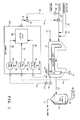
- FIG. 1 is a simplified schematic illustration of a polymerization reaction system and the associated control system of the present invention.
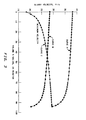
- FIG. 2 is a graph illustrating slurry velocity, pump pressure head and pump power as a function of volume percent solids for the reaction system as illustrated in FIG. 1.
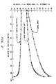
- FIG. 3 is a graph illustrating a minimum velocity which will prevent plugging; the slurry velocity achieved with a low capacity pump; and the slurry velocity achieved with a high capacity pump; with all variables displayed as a function of volume percent solids in the reaction mixture.
- This invention is described in terms of the polymerization of ethylene.
- the invention is applicable, however, to any process where it is desired to maintain a circulation velocity for a slurry in a pipe above a minimum value. It is particularly applicable to the optimization of solids concentration in a loop-type polymerization reactor, wherein the solids concentration is inferentially controlled.
- FIG. 1 A specific control system configuration is set forth in FIG. 1 for the sake of illustration.
- the specific control configuration is not a critical feature of the present invention, and the invention is applicable to a large variety of control configurations which may be utilized to accomplish the purpose of this invention.
- Lines designated as signal lines in the drawings are electrical or pneumatic in this preferred embodiment.
- the signals provided from any transducer are electrical in form.
- the signals provided from some sensors may be pneumatic in form. Transducing of these signals is not illustrated for the sake of simplicity because it is well known in the art that a measurement in pneumatic form must be transduced to electrical form if it is to be transmitted in electrical form. Also, transducing of signals from analog to digital form or from digital form to analog form is not illustrated because such transducing is also well known in the art.
- the invention is also applicable to mechanical, hydraulic or other means for transmitting information. In almost all control systems some combination of electrical, pneumatic, or hydraulic signals will be used. However, use of any other type of signal transmission, compatible with the process and equipment in use, is within the scope of the invention.
- a digital computer is used in the preferred embodiment of this invention to calculate, or select, the required control signal based on measured process parameters as well as set points supplied to the computer or controller.
- the digital computer is preferable an OPTROL® 7000 Process Computer System from Applied Automation, Inc., Bartlesville, Oklahoma.
- Signal lines are also utilized to represent the results of computer calculations or other operations accomplished in a digital computer, and the term "signal" is utilized to refer to such results.
- signal is used not only to refer to electrical currents or pneumatic pressures but is also used to refer to binary representations of a calculation or measured value.
- controllers shown can utilize the various modes of control such as proportional, proportional-integral, proportional-derivative,or proportional-integral-derivative.
- proportional-integral controllers are utilized but any controller having capacity to accept two or more input signals and to produce a scaled output signal, representative of a comparison of the input signals is within the scope of this invention.
- the scaling of an output signal by a controller is well known in control systems art. Essentially the output of a controller can be scaled to represent any desired factor or variable. An example of this is where a desired temperature and an actual temperature are compared by a controller.
- the controller output might be a signal representative of a flow rate of some gas necessary to make the desired and actual temperatures equal.
- the same output signal could be scaled to represent a pressure required to make the desired and actual temperatures equal. If the controller output can range from 0 to 10 volts, then the controller output signal could be scaled so that an output signal having a voltage level of 5.0 volts corresponds to 50 percent, some specified flow rate, or some specified pressure.
- an unselected controller In control systems utilizing select devices which select either the lowest, median, or highest control signal from among two or more signals, and wherein a controller output signal may or may not be selected from two or more signals, an unselected controller is in an open loop condition. If the unselected controller has integral action, which is most often the case, it needs to be protected against windup.
- the various transducing means used to measure parameters which characterize the process and the various signals generated thereby may take a variety of forms or formats.
- the control elements of the system can be implemented using electrical analog, digital electronic, pneumatic, hydraulic, mechanical or other similar types of equipment or combinations of such equipment types.
- This reactor 11 is a loop-type reactor which provides a continuous path for the circulation of the reaction mixture.
- a reactor can be made oblong in shape from straight pipe sections and ell's which are joined together to form a continuous flow path which is free of obstructions.
- Reactor 11 would typically be jacketed by heat exchange sections (not illustrated) for removing heat from the polymerization reaction.
- the reactor is also provided with suitable circulator or propelling means, such as a motor 31 which drives a propeller 33. In this type of reactor, the reaction mixture is propelled through the reaction zone at a velocity in the highly turbulent flow range.
- Ethylene is supplied to reactor 11 through conduit 13.
- a diluent such as isobutane, pentane, isopentane or mixtures thereof, is provided to the reactor 11 through conduit 15 and flow control valve 17.
- a catalyst such as a typical chromium oxide on silica catalyst or a silica-titania catalyst, is provided to polymerization reactor 11 through conduit 19.
- the catalyst for the reaction flowing through conduit 19, which is passed to the reactor 11 along with the isobutane diluent and possibly a comonomer, is introduced periodically into the reactor 11. This periodic or intermittent introduction of the catalyst is accomplished by the use of the catalyst feeder valve 21, which is located in conduit 19 so as to regulate the flow of catalyst.
- the reaction effluent is withdrawn from reactor 11 through conduit 23 and is passed to the flash tank 25.
- the reaction effluent will be made up of polyethylene, unreacted ethylene and isobutane.
- the catalyst will generally be contained in the polyethylene.
- the polyethylene is separated from the vaporized components, which comprise unreacted ethylene and isobutane, in the flash tank 25.
- Polyethylene is removed from the flash tank 25 through conduit 27.
- Unreacted ethylene and isobutane are withdrawn from the flash tank 25 through conduit 29 and passed to suitable separation equipment (not illustrated), to separate the unreacted monomer from the diluent which is then recycled back to the reaction system.
- the diluent supplied to the reactor 11 through conduit 15 does not react, but is used to control solids concentration in the reaction mixture.
- the set point signal 41 for the diluent flow rate controller 43 which is selected according to the present invention, is utilized to maintain the actual solids concentration at substantially the highest practical concentration without plugging the reactor, as will be more fully explained hereinafter.
- the polymerization reaction system described to this point is conventional. It is the manner in which the polymerization reaction system is operated and the manner in which the solids concentration is controlled so as to achieve the highest practical solids concentration without plugging the reactor that provide the novel features of this invention. Further information and details of the polymerization process, including examples of suitable reaction conditions, and also examples of other monomers, comonomers, diluents, etc., as well as suitable control schemes for other important variables, such as production rate, can be found in U.S. Patent No. 3,998,995 of Buss, et al, and U.S. Patent No. 3,257,363 of Miller, et al, the disclosures of which are incorporated herein by reference.
- a circulating pump power signal 51 which is representative of the actual power supplied to motor 31, is generated by a power transducer 53 which monitors the motor 31.
- the motor 31 will be an electric motor, and the power transducer 53 can comprise a wattmeter for providing a suitable power signal.
- Signal 51 is provided from transducer 53 as an input signal to computer 100.
- a differential pressure transducer 55 which is installed in elbow taps at an existing elbow of the loop-type reactor 11, provides an output signal 57, which is representative of the actual velocity of the slurry circulating in the fixed pipe diameter of loop reactor 11.
- Signal 57 is provided from pressure transducer 55 as an input signal to computer 100.
- a differential pressure transducer 58 which is installed in a section of the reactor pipe associated with the impeller 33, provides an output signal 59 which is representative of the pressure head arising from the pressure in the pipe produced by the circulation pump means comprising the motor 31 and impeller 33.
- Signal 59 is provided from pressure transducer 58 as an input signal to computer 100.
- a flow transducer 45 in combination with a flow sensing element such as an orifice 46 operably located in conduit 15, produces flow signal 49 which is representative of the flow rate of diluent flowing in conduit 15.
- Signal 49 is provided from transducer 45 as a process variable input signal to diluent flow controller 43.
- Flow controller 43 is also provided with the computer generated set point signal 41.
- Flow controller 43 provides an output signal 44 which is responsive to the difference between signals 41 and 49.
- Control signal 44 is scaled so as to be representative of the position of control valve 17 which is operably located in conduit 15, required to maintain the actual flow rate of the diluent through conduit 15 substantially equal to the desired flow rate represented by signal 41.
- Signal 44 is provided from the flow controller 43 as the control signal to control valve 17, and control valve l7 is manipulated in response thereto.
- any one of these variables could be controlled by manipulating the diluent flow rate, and thereby correspondingly control solids concentration, it is presently preferred to provide a controller for each of these variables and automatically select one of these three controllers to manipulate the diluent flow rate.
- the pipe-loop reactor is protected against polymer plugging by increasing the diluent flow rate if any one of the variables exceeds a desired value.
- the diluent flow rate is normally manipulated to control slurry velocity, but if a pressure head which indicates inadequate capacity to circulate the slurry is detected, the pressure head signal takes command of the diluent control valve 21 and increases diluent flow. Accordingly, the variable having the greatest positive deviation from its' set point (i.e. demands the greatest diluent flow rate to return to its' set point) is automatically selected to manipulate the diluent flow rate.
- Signal 51 which is representative of the actual power supplied to the slurry circulation motor 31, is provided as a process variable input to power controller 61 in computer 100.
- Power controller 61 is also provided with a set point signal 63 which is representative of the maximum circulation pump power permitted for maintaining a desired velocity, or head, for a given solids concentration.
- power controller 61 provides an output signal 65 which is responsive to the difference between signals 51 and 63.
- Control signal 65 is scaled so as to be representative of the diluent flow rate in conduit 15 required to maintain the actual pump power represented by signal 51 substantially equal to the pump power represented by signal 63.
- Signal 65 is provided from power controller 65 as a first input signal to the computer high select block 66.
- signal 57 which is representative of the actual slurry circulation velocity
- signal 59 which is representative of the actual pressure head in the loop reactor 11 are provided as process variable inputs to process controllers 71 and 81 respectively.
- Process controller 71 is also provided with a set point signal 73, which is representative of a minimum slurry velocity that will maintain the polymer solids in suspension in a slurry having a given solids concentration.
- slurry velocity controller 71 provides an output signal 75 which is responsive to the difference between signals 57 and 73.
- Control signal 75 is scaled so as to be representative of the diluent flow rate in conduit 15 required to maintain the actual slurry velocity represented by signal 57 substantially equal to slurry velocity represented by signal 73.
- Signal 75 is provided from slurry velocity controller 71 as a second input to the computer high select block 66.
- pressure head controller 81 is also provided with a set point signal 83 which is representative of the maximum pressure head at a point in the pipe required to circulate the slurry, having a given solids concentration, at the minimum circulation velocity.
- pressure head controller 81 provides an output signal 85 which is responsive to the difference between signals 59 and 83.
- Control signal 85 is scaled so as to be representative of the diluent flow rate in conduit 15 required to maintain the actual pressure head represented by signal 59 substantially equal to the pressure head represented by signal 83.
- the set point signals 63, 73, and 83 will be selected with the aid of a figure similar to FIG. 2, or from previous operating experience. In either event, each of the values for the set point signals 63, 73, and 83 will correspond to a desired solids concentration for the reaction slurry.
- This graph also shows a plot of two other critical slurry circulation velocities as a function of volume percent solids concentration in the reaction slurry, i.e., curve A, in FIG. 3, shows the circulation velocity achieved with a high capacity circulation pump; curve B shows the velocity achieved with a low capacity pump.
- curve A shows the circulation velocity achieved with a high capacity circulation pump;
- curve B shows the velocity achieved with a low capacity pump.
- curve C indicates the maximum slurry solids concentration that can be maintained by the respective pumps.
- Curves A and B of FIG. 3 represent numerous calculated data points to clearly illustrate the sharp drop-off in circulation velocity as the solids concentration exceeds about 80 volume percent solids.
- Curve C which illustrates the increase in circulation velocity required as the solids concentration increases, was calculated in accordance with the aforementioned Durand Equation.
- an olefin feed stream consisting of 1,675 lbs/hr. of ethylene, 16 lbs/hr. of hexene-1, and 916 lbs/hr. of isobutane, and having a pressure of 600 psig is fed to a pipe loop reactor along with 0.51 lbs./hr. of a chromium oxide-silica aluminia catalyst, the catalyst having a productivity of 3,190 lbs. polymer/lb. catalyst.
- the reactor itself has a capacity of 600 gallons.
- Polymer was withdrawn at a rate of 1,635 lbs./hr.; along with 916 lbs./hr. of isobutane; 39 lbs./hr. of ethylene; and 1.6 lbs/hr. of hexene-1.
- the reaction temperature was maintained below 230°F and was preferably in the range of 150° - 225°F with a reactor residence time of about 1.2 hours.
- the volume percent solids in the reactor was measured by visually observing the solids level of a representative captive sample of the reaction mixture which was allowed to settle at saturation pressure in a sight glass.
- the volume percent solids is determined by observing the height of the settled polymer particles in the sight glass and dividing this observed height by the height of the total captive sample of the reaction mixture, and wherein the cross sectional area of the sight glass containing the captive sample is the same as the cross sectional area of the vertical pipe of the pipe-loop reactor.
- the weight percent solids of the effluent for the developmental plant reactor was calculated based on a material balance using the measured reactor feed rates, and an analysis the effluent flash gas.
- Resin types A, B and C are examples of typical resins commercially produced in a pipe-loop reactor, wherein resin A has a density of .955 g/cc, resin B has a density of .962 g/cc, and resin C has a density of .937 g/cc.
- the invention has been described in terms of a preferred embodiment as illustrated in FIG's. 1-3.
- Specific components used in the practice of this invention as illustrated in FIG. 1 which have not been previously specified, such as control valve 17, flow controller 43, flow transducer 44, flow sensor 46, differential pressure transducers 57 and 55, and power transducer 53, are each well known, commercially available components such as are described at length in "Perry's Chemical Engineers' Handbook", Fifth Edition, Chapter 22, McGraw-Hill.
- the catalyst feeder valve 21 may be a Seiscore ball check feeder valve.
Landscapes
- Chemical & Material Sciences (AREA)
- Organic Chemistry (AREA)
- Chemical Kinetics & Catalysis (AREA)
- Engineering & Computer Science (AREA)
- Automation & Control Theory (AREA)
- Health & Medical Sciences (AREA)
- Medicinal Chemistry (AREA)
- Polymers & Plastics (AREA)
- Physics & Mathematics (AREA)
- General Physics & Mathematics (AREA)
- Polymerisation Methods In General (AREA)
- Physical Or Chemical Processes And Apparatus (AREA)
Applications Claiming Priority (2)
| Application Number | Priority Date | Filing Date | Title |
|---|---|---|---|
| US44172889A | 1989-11-27 | 1989-11-27 | |
| US441728 | 1989-11-27 |
Publications (2)
| Publication Number | Publication Date |
|---|---|
| EP0432555A2 true EP0432555A2 (de) | 1991-06-19 |
| EP0432555A3 EP0432555A3 (en) | 1991-10-09 |
Family
ID=23754052
Family Applications (1)
| Application Number | Title | Priority Date | Filing Date |
|---|---|---|---|
| EP19900122526 Withdrawn EP0432555A3 (en) | 1989-11-27 | 1990-11-26 | Control of polymerization reaction |
Country Status (4)
| Country | Link |
|---|---|
| EP (1) | EP0432555A3 (de) |
| JP (1) | JPH03181501A (de) |
| CA (1) | CA2023745A1 (de) |
| NO (1) | NO905133L (de) |
Cited By (29)
| Publication number | Priority date | Publication date | Assignee | Title |
|---|---|---|---|---|
| EP0891990A3 (de) * | 1997-07-15 | 1999-11-10 | Phillips Petroleum Company | Suspensionspolymerisation mit hohem Feststoffgehalt |
| EP1118624A1 (de) * | 2000-01-18 | 2001-07-25 | SOLVAY POLYOLEFINS EUROPE - BELGIUM (Société Anonyme) | Verfahren zur Herstellung von Olefinpolymeren |
| US6566460B1 (en) | 2000-08-04 | 2003-05-20 | Equistar Chemicals, Lp | Continuous recovery of polymer from a slurry loop reactor |
| US6586537B2 (en) | 2000-01-18 | 2003-07-01 | Solvay Polyolefins Europe-Belgium (Societe Anonyme) | Process for manufacturing an olefin polymer composition |
| US6670431B2 (en) | 1998-03-20 | 2003-12-30 | Exxonmobil Chemical Patents, Inc. | Continuous slurry polymerization volatile removal |
| US6800698B2 (en) | 1998-03-20 | 2004-10-05 | Exxonmobil Chemical Patents, Inc. | Continuous slurry polymerization volatile removal |
| EP1563903A1 (de) * | 2004-02-13 | 2005-08-17 | Total Petrochemicals Research Feluy | Steuerung der Schwellung in einem Schlaufenreaktor |
| US7034090B2 (en) | 1998-03-20 | 2006-04-25 | Exxonmobil Chemical Patents Inc. | Continuous slurry polymerization volatile removal |
| WO2006056756A1 (en) * | 2004-11-26 | 2006-06-01 | Ineos Manufacturing Belgium Nv | Slurry phase polymerisation process |
| US7268194B2 (en) | 1998-03-20 | 2007-09-11 | Exxonmobil Chemical Patents Inc. | Continuous slurry polymerization process and apparatus |
| WO2007040996A3 (en) * | 2005-09-30 | 2007-10-04 | Chevron Phillips Chemical Co | Multiple component feed methods and systems |
| WO2006026224A3 (en) * | 2004-08-27 | 2009-07-02 | Chevron Phillips Chemical Co | Method and system to reduce polymerization reactor fouling |
| US7572866B2 (en) | 2004-11-26 | 2009-08-11 | Ineos Manufacturing Belgium Nv | Slurry phase polymerisation process |
| CN100532401C (zh) * | 2003-10-31 | 2009-08-26 | 切夫里昂菲利普化学有限责任公司 | 在旋风分离器中聚合物颗粒和蒸发的稀释剂的分离 |
| EP2110173A1 (de) | 2008-04-16 | 2009-10-21 | INEOS Manufacturing Belgium NV | Polymerstromübertragung |
| US7632899B2 (en) | 2004-11-26 | 2009-12-15 | Ineos Manufacturing Belgium Nv | Slurry phase polymerisation process |
| EP2156885A2 (de) | 2006-05-26 | 2010-02-24 | INEOS Manufacturing Belgium NV | Verfahren zur Polymerisation |
| EP2316863A1 (de) | 2009-10-30 | 2011-05-04 | INEOS Manufacturing Belgium NV | Polymerisationsprozess in der Schlammphase |
| US8058367B2 (en) | 2004-08-27 | 2011-11-15 | Chevron Phillips Chemical Company Lp | Methods and systems for controlling polymer particle size |
| EP2397221A1 (de) * | 2010-06-17 | 2011-12-21 | Borealis AG | Steuerungssystem für ein Gasphasenreaktor, Gasphasenreaktor für katalytische Herstellung von Polyolefinen, Verfahren zur katalytischen Herstellung von Polyolefinen und zur Verwendung des Steuerungssystems |
| WO2012005740A1 (en) * | 2010-07-08 | 2012-01-12 | Exxonmobil Chemical Patents Inc. | Method for controlling bubble formation in polymerization reactors |
| US8648156B2 (en) | 2010-05-12 | 2014-02-11 | Ineos Commercial Services Uk Limited | Reactor |
| US8816024B2 (en) | 2010-05-21 | 2014-08-26 | Chevron Phillips Chemical Company Lp | Continuous take off technique and pressure control of polymerization reactors |
| US9296833B2 (en) | 2010-07-08 | 2016-03-29 | Exxonmobil Chemical Patents Inc. | Method for controlling bubble formation in polymerization reactors |
| WO2017102958A1 (en) | 2015-12-17 | 2017-06-22 | Total Research & Technology Feluy | Process for determining one or more operating conditions of an olefin polymerization reactor |
| US10029230B1 (en) | 2017-01-24 | 2018-07-24 | Chevron Phillips Chemical Company Lp | Flow in a slurry loop reactor |
| WO2020163093A1 (en) * | 2019-02-05 | 2020-08-13 | Exxonmobil Chemical Patents Inc. | Recycle diluent control and optimization for slurry loop polyethylene reactors |
| CN112762359A (zh) * | 2021-01-05 | 2021-05-07 | 宁夏宝丰能源集团股份有限公司 | 一种抑制聚合反应的装置和聚合反应成套设备 |
| US12466900B2 (en) | 2022-04-19 | 2025-11-11 | Chevron Phillips Chemical Company Lp | Loop slurry periodogram control to prevent reactor fouling and reactor shutdowns |
Families Citing this family (1)
| Publication number | Priority date | Publication date | Assignee | Title |
|---|---|---|---|---|
| SA04250276B1 (ar) * | 2003-09-24 | 2009-02-07 | باسيل بوليوليفين جي ام بي اتش | عملية بلمرة لوسط معلق مع تركيزات عالية للمواد الصلبة خلال مفاعل حلقي |
Family Cites Families (4)
| Publication number | Priority date | Publication date | Assignee | Title |
|---|---|---|---|---|
| US3257363A (en) * | 1961-05-22 | 1966-06-21 | Phillips Petroleum Co | Control of the composition of a reaction mixture |
| US3998995A (en) * | 1974-12-02 | 1976-12-21 | Phillips Petroleum Company | Polymerization method and apparatus |
| US4059745A (en) * | 1976-09-29 | 1977-11-22 | Fischer & Porter Co. | Override process control system |
| US4543637A (en) * | 1982-07-16 | 1985-09-24 | Phillips Petroleum Company | Generation of a set point for process control |
-
1990
- 1990-08-22 CA CA002023745A patent/CA2023745A1/en not_active Abandoned
- 1990-11-22 JP JP32060590A patent/JPH03181501A/ja active Pending
- 1990-11-26 EP EP19900122526 patent/EP0432555A3/en not_active Withdrawn
- 1990-11-27 NO NO90905133A patent/NO905133L/no unknown
Cited By (69)
| Publication number | Priority date | Publication date | Assignee | Title |
|---|---|---|---|---|
| US6743869B2 (en) | 1997-07-15 | 2004-06-01 | Phillips Petroleum Company | High polymer solids slurry polymerization employing 1-olefin comonomer |
| EP0891990A3 (de) * | 1997-07-15 | 1999-11-10 | Phillips Petroleum Company | Suspensionspolymerisation mit hohem Feststoffgehalt |
| EP0891990B2 (de) † | 1997-07-15 | 2016-01-20 | Chevron Phillips Chemical Company Lp | Suspensionspolymerisation mit hohem Feststoffgehalt |
| US6806324B2 (en) | 1997-07-15 | 2004-10-19 | Phillips Petroleum Company | High solids slurry polymerization using heat exchange to condense the flashed diluent |
| US7268194B2 (en) | 1998-03-20 | 2007-09-11 | Exxonmobil Chemical Patents Inc. | Continuous slurry polymerization process and apparatus |
| US6858682B2 (en) | 1998-03-20 | 2005-02-22 | Exxonmobil Chemical Patents, Inc. | Continuous slurry polymerization volatile removal |
| US7034090B2 (en) | 1998-03-20 | 2006-04-25 | Exxonmobil Chemical Patents Inc. | Continuous slurry polymerization volatile removal |
| US6670431B2 (en) | 1998-03-20 | 2003-12-30 | Exxonmobil Chemical Patents, Inc. | Continuous slurry polymerization volatile removal |
| US7575724B2 (en) | 1998-03-20 | 2009-08-18 | Exxonmobil Chemical Patents Inc. | Continuous slurry polymerization apparatus |
| US6800698B2 (en) | 1998-03-20 | 2004-10-05 | Exxonmobil Chemical Patents, Inc. | Continuous slurry polymerization volatile removal |
| US6926868B2 (en) | 1998-03-20 | 2005-08-09 | Exxonmobil Chemical Patents Inc. | Continuous slurry polymerization volatile removal |
| US6833415B2 (en) | 1998-03-20 | 2004-12-21 | Exxonmobil Chemical Patents, Inc. | Continuous slurry polymerization process and appparatus |
| EP1118624A1 (de) * | 2000-01-18 | 2001-07-25 | SOLVAY POLYOLEFINS EUROPE - BELGIUM (Société Anonyme) | Verfahren zur Herstellung von Olefinpolymeren |
| US6489409B2 (en) | 2000-01-18 | 2002-12-03 | Solvay Polyolefins Europe-Belgium (Societe Anonyme) | Process for manufacturing olefin polymers |
| US6586537B2 (en) | 2000-01-18 | 2003-07-01 | Solvay Polyolefins Europe-Belgium (Societe Anonyme) | Process for manufacturing an olefin polymer composition |
| US6596823B2 (en) | 2000-01-18 | 2003-07-22 | Solvay Polyolefins Europe-Belgium (Societe Anonyme) | Process for manufacturing a polyolefin resin |
| BE1013236A3 (fr) * | 2000-01-18 | 2001-11-06 | Solvay | Procede de fabrication de polymeres d'olefines. |
| US6566460B1 (en) | 2000-08-04 | 2003-05-20 | Equistar Chemicals, Lp | Continuous recovery of polymer from a slurry loop reactor |
| CN100532401C (zh) * | 2003-10-31 | 2009-08-26 | 切夫里昂菲利普化学有限责任公司 | 在旋风分离器中聚合物颗粒和蒸发的稀释剂的分离 |
| WO2005082518A3 (en) * | 2004-02-13 | 2005-10-27 | Total Petrochemicals Res Feluy | Swell control in slurry loop reactor |
| EA010798B1 (ru) * | 2004-02-13 | 2008-12-30 | Тотал Петрокемикалс Рисерч Фелюй | Способ осуществления полимеризации олефина |
| EP1563903A1 (de) * | 2004-02-13 | 2005-08-17 | Total Petrochemicals Research Feluy | Steuerung der Schwellung in einem Schlaufenreaktor |
| WO2006026224A3 (en) * | 2004-08-27 | 2009-07-02 | Chevron Phillips Chemical Co | Method and system to reduce polymerization reactor fouling |
| US8187547B2 (en) | 2004-08-27 | 2012-05-29 | Chevron Phillips Chemical Company Lp | Methods and systems for controlling polymer particle size |
| CN101432066B (zh) * | 2004-08-27 | 2014-03-19 | 切夫里昂菲利普化学有限责任公司 | 减少聚合反应器结垢的方法与系统 |
| US7645841B2 (en) | 2004-08-27 | 2010-01-12 | Chevron Phillips Chemical Company Lp | Method and system to reduce polymerization reactor fouling |
| US8058367B2 (en) | 2004-08-27 | 2011-11-15 | Chevron Phillips Chemical Company Lp | Methods and systems for controlling polymer particle size |
| US7781546B2 (en) | 2004-11-26 | 2010-08-24 | Ineos Manufacturing Belgium Nv | Slurry phase polymerisation process |
| US8580202B2 (en) | 2004-11-26 | 2013-11-12 | Ineos Manufacturing Belgium Nv | Slurry phase polymerisation process |
| US9567408B2 (en) | 2004-11-26 | 2017-02-14 | Ineos Manufacturing Belgium Nv | Slurry phase polymerisation process |
| WO2006056756A1 (en) * | 2004-11-26 | 2006-06-01 | Ineos Manufacturing Belgium Nv | Slurry phase polymerisation process |
| US9212242B2 (en) | 2004-11-26 | 2015-12-15 | Ineos Manufacturing Belgium Nv | Slurry phase polymerisation process |
| EP2168676A1 (de) | 2004-11-26 | 2010-03-31 | INEOS Manufacturing Belgium NV | Polymerisationsprozess in der Schlammphase |
| EP2177542A1 (de) | 2004-11-26 | 2010-04-21 | INEOS Manufacturing Belgium NV | Polymerisationsprozess in der Schlammphase |
| US8927665B2 (en) | 2004-11-26 | 2015-01-06 | Ineos Manufacturing Belgium Nv | Slurry phase polymerisation process |
| US7790119B2 (en) | 2004-11-26 | 2010-09-07 | Ineos Manufacturing Belgium Nv | Slurry phase polymerisation process |
| US7820116B2 (en) | 2004-11-26 | 2010-10-26 | Ineos Manufacturing Belgium Nv | Slurry phase polymerisation process |
| EA014494B1 (ru) * | 2004-11-26 | 2010-12-30 | Инеос Мэньюфекчуринг Белджиум Нв | Способ полимеризации олефинового мономера и реактор с циркуляцией непрерывной трубной конструкции |
| EP2277921A1 (de) | 2004-11-26 | 2011-01-26 | INEOS Manufacturing Belgium NV | Polymerisationsprozess in der Schlammphase |
| EP2277621A2 (de) | 2004-11-26 | 2011-01-26 | INEOS Manufacturing Belgium NV | Polymerisationsprozess in der Schlammphase |
| US7632899B2 (en) | 2004-11-26 | 2009-12-15 | Ineos Manufacturing Belgium Nv | Slurry phase polymerisation process |
| EA017776B1 (ru) * | 2004-11-26 | 2013-03-29 | Инеос Мэньюфекчуринг Белджиум Нв | Способ полимеризации в суспензионной фазе и реакторная система |
| US7572866B2 (en) | 2004-11-26 | 2009-08-11 | Ineos Manufacturing Belgium Nv | Slurry phase polymerisation process |
| US8101692B2 (en) | 2004-11-26 | 2012-01-24 | Ineos Manufacturing Belgium Nv | Slurry phase polymerisation process |
| WO2007040996A3 (en) * | 2005-09-30 | 2007-10-04 | Chevron Phillips Chemical Co | Multiple component feed methods and systems |
| US7615596B2 (en) | 2005-09-30 | 2009-11-10 | Chevron Phillips Chemical Company Lp | Multiple component feed methods and systems |
| US8992840B2 (en) | 2005-09-30 | 2015-03-31 | Chevron Phillips Chemical Company Lp | Multiple component feed methods and systems |
| EP2156885A2 (de) | 2006-05-26 | 2010-02-24 | INEOS Manufacturing Belgium NV | Verfahren zur Polymerisation |
| EP2156884A2 (de) | 2006-05-26 | 2010-02-24 | INEOS Manufacturing Belgium NV | Verfahren zur Polymerisation |
| EP2156886A2 (de) | 2006-05-26 | 2010-02-24 | INEOS Manufacturing Belgium NV | Polymerisationsprozess in der Schlammphase |
| EP2110173A1 (de) | 2008-04-16 | 2009-10-21 | INEOS Manufacturing Belgium NV | Polymerstromübertragung |
| WO2011051367A1 (en) | 2009-10-30 | 2011-05-05 | Ineos Manufacturing Belgium Nv | Slurry phase polymerisation process |
| EP2316863A1 (de) | 2009-10-30 | 2011-05-04 | INEOS Manufacturing Belgium NV | Polymerisationsprozess in der Schlammphase |
| US8648156B2 (en) | 2010-05-12 | 2014-02-11 | Ineos Commercial Services Uk Limited | Reactor |
| US8816024B2 (en) | 2010-05-21 | 2014-08-26 | Chevron Phillips Chemical Company Lp | Continuous take off technique and pressure control of polymerization reactors |
| EP2397221A1 (de) * | 2010-06-17 | 2011-12-21 | Borealis AG | Steuerungssystem für ein Gasphasenreaktor, Gasphasenreaktor für katalytische Herstellung von Polyolefinen, Verfahren zur katalytischen Herstellung von Polyolefinen und zur Verwendung des Steuerungssystems |
| US9243988B2 (en) | 2010-07-08 | 2016-01-26 | Exxonmobil Chemical Patents Inc. | System and method for monitoring bubble formation within a reactor |
| US9296833B2 (en) | 2010-07-08 | 2016-03-29 | Exxonmobil Chemical Patents Inc. | Method for controlling bubble formation in polymerization reactors |
| WO2012005740A1 (en) * | 2010-07-08 | 2012-01-12 | Exxonmobil Chemical Patents Inc. | Method for controlling bubble formation in polymerization reactors |
| WO2017102958A1 (en) | 2015-12-17 | 2017-06-22 | Total Research & Technology Feluy | Process for determining one or more operating conditions of an olefin polymerization reactor |
| KR20180095585A (ko) * | 2015-12-17 | 2018-08-27 | 토탈 리서치 앤드 테크놀로지 펠루이 | 올레핀 중합 반응기의 하나 이상의 작동 조건을 결정하기 위한 방법 |
| CN108473626A (zh) * | 2015-12-17 | 2018-08-31 | 道达尔研究技术弗吕公司 | 用于确定烯烃聚合反应器的一个或多个操作条件的方法 |
| US10730970B2 (en) | 2015-12-17 | 2020-08-04 | Total Research & Technology Feluy | Process for determining one or more operating conditions of an olefin polymerization reactor |
| KR102647946B1 (ko) | 2015-12-17 | 2024-03-14 | 토탈에너지스 원테크 벨지움 | 올레핀 중합 반응기의 하나 이상의 작동 조건을 결정하기 위한 방법 |
| US10029230B1 (en) | 2017-01-24 | 2018-07-24 | Chevron Phillips Chemical Company Lp | Flow in a slurry loop reactor |
| WO2020163093A1 (en) * | 2019-02-05 | 2020-08-13 | Exxonmobil Chemical Patents Inc. | Recycle diluent control and optimization for slurry loop polyethylene reactors |
| US12116430B2 (en) | 2019-02-05 | 2024-10-15 | Exxonmobil Chemical Patents Inc. | Recycle diluent control and optimization for slurry loop polyethylene reactors |
| CN112762359A (zh) * | 2021-01-05 | 2021-05-07 | 宁夏宝丰能源集团股份有限公司 | 一种抑制聚合反应的装置和聚合反应成套设备 |
| US12466900B2 (en) | 2022-04-19 | 2025-11-11 | Chevron Phillips Chemical Company Lp | Loop slurry periodogram control to prevent reactor fouling and reactor shutdowns |
Also Published As
| Publication number | Publication date |
|---|---|
| JPH03181501A (ja) | 1991-08-07 |
| CA2023745A1 (en) | 1991-05-28 |
| EP0432555A3 (en) | 1991-10-09 |
| NO905133L (no) | 1991-05-28 |
| NO905133D0 (no) | 1990-11-27 |
Similar Documents
| Publication | Publication Date | Title |
|---|---|---|
| JPH03181501A (ja) | 重合反応の制御方法及び装置 | |
| US3242150A (en) | Method and apparatus for the recovery of solid olefin polymer from a continuous path reaction zone | |
| US5565174A (en) | Apparatus for controlling removal of polymerization reaction effluent | |
| US3324093A (en) | Loop reactor | |
| US3374211A (en) | Solids recovery from a flowing stream | |
| CA2498681C (en) | Loop reactor apparatus and polymerization processes with multiple feed points for olefins and catalysts | |
| US3203766A (en) | Apparatus for the recovery of solids from pressure vessels | |
| US4543637A (en) | Generation of a set point for process control | |
| US20030130553A1 (en) | Alkylation process | |
| EP1789177B1 (de) | Polymerisationsreaktoren mit bypass-leitung | |
| US9963523B2 (en) | Polyethylene production with multiple polymerization reactors | |
| EP2277621B1 (de) | Polymerisationsprozess in der Schlammphase | |
| EP1988992B1 (de) | Verbindungsrohr zwischen zwei schleifenreaktoren | |
| EP2348056A1 (de) | Verfahren zur Gasphase Polymenisation von Olefinen | |
| US4392877A (en) | Constraint control of a fractional distillation process | |
| EP0028824A1 (de) | Verfahren zur Kontrolle der Temperaturdifferenz entlang einer Reaktionszone zur Herstellung von Methyl-tert-butyl-Äther | |
| EP2931414B1 (de) | Herstellung von polyethylen mit mehreren polymerisationsreaktoren | |
| EP0088427A1 (de) | Vorrichtung und Verfahren zum Steuern eines Alkylierungsreaktors | |
| US4713774A (en) | Alkylation reactor quality control | |
| Hyanek et al. | Dynamics and stability of polymerization process flow sheets | |
| US4846850A (en) | Absorption pressure control | |
| US4628034A (en) | Control of a polymerization reaction | |
| US4371499A (en) | Control of a fluid catalytic cracking unit | |
| EP2177542A1 (de) | Polymerisationsprozess in der Schlammphase | |
| US4184027A (en) | Recycle control system for continuous polymerization |
Legal Events
| Date | Code | Title | Description |
|---|---|---|---|
| PUAI | Public reference made under article 153(3) epc to a published international application that has entered the european phase |
Free format text: ORIGINAL CODE: 0009012 |
|
| AK | Designated contracting states |
Kind code of ref document: A2 Designated state(s): AT BE CH DE DK ES FR GB GR IT LI LU NL SE |
|
| PUAL | Search report despatched |
Free format text: ORIGINAL CODE: 0009013 |
|
| AK | Designated contracting states |
Kind code of ref document: A3 Designated state(s): AT BE CH DE DK ES FR GB GR IT LI LU NL SE |
|
| 17P | Request for examination filed |
Effective date: 19920310 |
|
| 17Q | First examination report despatched |
Effective date: 19930705 |
|
| STAA | Information on the status of an ep patent application or granted ep patent |
Free format text: STATUS: THE APPLICATION IS DEEMED TO BE WITHDRAWN |
|
| 18D | Application deemed to be withdrawn |
Effective date: 19931116 |