EP0432603B1 - Convertisseur continu-continu, en particulier du type quasi-résonant - Google Patents
Convertisseur continu-continu, en particulier du type quasi-résonant Download PDFInfo
- Publication number
- EP0432603B1 EP0432603B1 EP90123065A EP90123065A EP0432603B1 EP 0432603 B1 EP0432603 B1 EP 0432603B1 EP 90123065 A EP90123065 A EP 90123065A EP 90123065 A EP90123065 A EP 90123065A EP 0432603 B1 EP0432603 B1 EP 0432603B1
- Authority
- EP
- European Patent Office
- Prior art keywords
- direct voltage
- voltage converter
- winding
- smoothing
- determining resonance
- Prior art date
- Legal status (The legal status is an assumption and is not a legal conclusion. Google has not performed a legal analysis and makes no representation as to the accuracy of the status listed.)
- Expired - Lifetime
Links
- 238000009499 grossing Methods 0.000 claims description 33
- 238000004804 winding Methods 0.000 claims description 24
- 239000003990 capacitor Substances 0.000 claims description 21
- 230000001939 inductive effect Effects 0.000 claims description 13
- 230000005540 biological transmission Effects 0.000 claims description 2
- 230000006698 induction Effects 0.000 claims 1
- 230000001105 regulatory effect Effects 0.000 claims 1
- 230000005669 field effect Effects 0.000 description 3
- 238000010586 diagram Methods 0.000 description 2
- 238000002955 isolation Methods 0.000 description 2
- 230000005347 demagnetization Effects 0.000 description 1
- 238000011156 evaluation Methods 0.000 description 1
- 230000002349 favourable effect Effects 0.000 description 1
- 230000010363 phase shift Effects 0.000 description 1
- 230000001960 triggered effect Effects 0.000 description 1
Images




Classifications
-
- H—ELECTRICITY
- H02—GENERATION; CONVERSION OR DISTRIBUTION OF ELECTRIC POWER
- H02M—APPARATUS FOR CONVERSION BETWEEN AC AND AC, BETWEEN AC AND DC, OR BETWEEN DC AND DC, AND FOR USE WITH MAINS OR SIMILAR POWER SUPPLY SYSTEMS; CONVERSION OF DC OR AC INPUT POWER INTO SURGE OUTPUT POWER; CONTROL OR REGULATION THEREOF
- H02M3/00—Conversion of DC power input into DC power output
- H02M3/22—Conversion of DC power input into DC power output with intermediate conversion into AC
- H02M3/24—Conversion of DC power input into DC power output with intermediate conversion into AC by static converters
- H02M3/28—Conversion of DC power input into DC power output with intermediate conversion into AC by static converters using discharge tubes with control electrode or semiconductor devices with control electrode to produce the intermediate AC
- H02M3/325—Conversion of DC power input into DC power output with intermediate conversion into AC by static converters using discharge tubes with control electrode or semiconductor devices with control electrode to produce the intermediate AC using devices of a triode or a transistor type requiring continuous application of a control signal
- H02M3/335—Conversion of DC power input into DC power output with intermediate conversion into AC by static converters using discharge tubes with control electrode or semiconductor devices with control electrode to produce the intermediate AC using devices of a triode or a transistor type requiring continuous application of a control signal using semiconductor devices only
- H02M3/33538—Conversion of DC power input into DC power output with intermediate conversion into AC by static converters using discharge tubes with control electrode or semiconductor devices with control electrode to produce the intermediate AC using devices of a triode or a transistor type requiring continuous application of a control signal using semiconductor devices only of the forward type
- H02M3/33546—Conversion of DC power input into DC power output with intermediate conversion into AC by static converters using discharge tubes with control electrode or semiconductor devices with control electrode to produce the intermediate AC using devices of a triode or a transistor type requiring continuous application of a control signal using semiconductor devices only of the forward type with automatic control of the output voltage or current
-
- Y—GENERAL TAGGING OF NEW TECHNOLOGICAL DEVELOPMENTS; GENERAL TAGGING OF CROSS-SECTIONAL TECHNOLOGIES SPANNING OVER SEVERAL SECTIONS OF THE IPC; TECHNICAL SUBJECTS COVERED BY FORMER USPC CROSS-REFERENCE ART COLLECTIONS [XRACs] AND DIGESTS
- Y02—TECHNOLOGIES OR APPLICATIONS FOR MITIGATION OR ADAPTATION AGAINST CLIMATE CHANGE
- Y02B—CLIMATE CHANGE MITIGATION TECHNOLOGIES RELATED TO BUILDINGS, e.g. HOUSING, HOUSE APPLIANCES OR RELATED END-USER APPLICATIONS
- Y02B70/00—Technologies for an efficient end-user side electric power management and consumption
- Y02B70/10—Technologies improving the efficiency by using switched-mode power supplies [SMPS], i.e. efficient power electronics conversion e.g. power factor correction or reduction of losses in power supplies or efficient standby modes
Definitions
- the invention relates to a direct voltage converter according to the preamble of patent claim 1.
- DC-DC converters are known (EP 0330 987; IEEE Power Electronics Specialists Conference, elle Paul Sabatier, Toulouse, France, 1985, pages 106 to 116).
- DC-DC converters based on the chopper principle are connected with inductive and capacitive elements to increase the working frequency so that the actuator can be switched loss-free at zero crossing.
- the additional circuitry impresses quasi-sinusoidal currents.
- the invention has for its object to design such a DC converter so that it has good dynamic behavior, i.e. can adapt to rapid load changes. This object is achieved by the features of patent claim 1. Advantageous training courses are shown in the subclaims.
- the DC-DC converter according to the invention is characterized in that during the energy transfer phase of the DC-DC converter - actuator switched on - part of the resonance current can flow without delay, ie directly into the smoothing capacitor on the output side, or to the load without a phase shift. This means that the influence of the phase rotation of the smoothing choke is considerably reduced. This increases the phase reserve of the control loop and improves the dynamic behavior of the controller, especially in the event of load jumps.
- the smoothing choke also works as a current converter.
- the inductance of the additional inductive element or part of the smoothing choke, in conjunction with the capacitive element, essentially determines the resonance frequency of the current half-wave.
- the leakage inductance of the additional current transformer is negligible. After opening the actuator, only the smoothing choke works.
- the quasi-resonance converter shown in FIG. 1 works according to the forward converter principle with electrical isolation between the DC voltage supply circuit and the DC voltage load circuit.
- the DC voltage source QE is connected to the primary winding t1 of the transformer Tr via the switching regulator actuator S1.
- the secondary winding t2 of the transformer Tr is via the series connection of rectifiers D1 and Smoothing choke L is connected to the output-side smoothing capacitor CG, which is parallel to the load RL.
- the freewheeling diode common to the forward converter is designated DF.
- the resonance-determining capacitive element - capacitor CR - of the quasi-resonance converter is arranged parallel to the freewheeling diode DF.
- the inductive resonance-determining element of the quasi-resonance converter is either part of the smoothing inductor L or an additional inductive element L 'magnetically coupled to the smoothing inductor L. As shown in FIG. 1, the inductive element L 'lies between the rectifier D1 and the connection point of the cathode of the freewheeling diode DF with the smoothing inductor L.
- the winding direction of the winding on the element L' is in relation to the winding direction of the winding on the smoothing inductor L - in Figure 1 marked by a point - such that during the energy transfer of the DC-DC converter - the switching regulator actuator S1 is then closed - part of the resonance current can flow to the output of the DC-DC converter, or in its smoothing capacitor CG on the output side.
- the smoothing choke L works together with the inductive element L 'as a current transformer. In connection with the capacitor CR, the inductance of the inductive element L 'essentially determines the resonance frequency of the current half-wave.
- the ratio of the number of turns of the winding on the smoothing inductor L to the number of turns of the winding on the additional inductive element L ' is chosen to be greater than 1, for example 4. This ratio is optimized according to the application in terms of efficiency and dynamic properties.
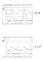
- the course of the current half-wave, current i1 via the rectifier D1 and the element L ', is shown in FIG. A timeline graduation corresponds to one microsecond (1E-6S / DIV) in FIGS. 2 to 11.
- the current i3 flowing through the smoothing capacitor CG is shown in FIG. It is a pure alternating current.
- the capacitor CR and the smoothing capacitor CG are routed together via the primary winding WI of an additional current transformer SW.
- this current transformer SI is designed as a toroidal core transformer
- the primary winding WI can be realized simply by plugging the common supply line of the capacitors CR and CG to the load terminal not directly connected to the smoothing inductor L through the remaining hole in the toroidal core.
- the current i3 generates a voltage drop UMESS on the secondary winding WII of the current transformer SW (FIG. 5), which is detected by the current measuring resistor RM.
- the AC voltage at the current measuring resistor RM is rectified in such a way that the voltage plateau proportional to the load current is peak-integrated (rectifier D2, resistor R1, capacitor C1 in FIG. 12).
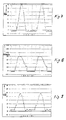
- the remaining oscillograms show the drain voltage UDrain at the field effect transistor S1 (FIG. 8), the voltage U3 at the output of the rectifier D1 (FIG. 9), the current i4 from Connection point of the inductors L, L 'to the resonance capacitor CR ( Figure 10) and the voltage U5 across the smoothing inductor L ( Figure 11).
- the invention can of course also be used for a direct voltage converter without electrical isolation, in which the transformer Tr is omitted.
- the controller for controlling the switching regulator actuator S1 consists of a VCO (voltage controlled oscillator), to which the peak current-integrated voltage proportional to the capacitor C1, possibly amplified via a control amplifier RV, can be supplied as a control voltage.
- a monoflop MF is connected downstream of the VCO and is triggered by the output signal of the VCO. With this arrangement, the switching regulator actuator S1 is supplied with switch-on pulses of constant duration.
- the switch-off duration of the switching regulator actuator S1 is variable and depends on the output voltage UA. A high output voltage UA leads to a long switch-off duration of the switching regulator actuator S1 and a low output voltage UA leads to a short switch-off duration.
- the energy supply to the controller can take place during the time during which a sufficiently high current i2 flows through the smoothing inductor L via an additional winding W1 on the core of the smoothing inductor L.
- the winding W1 is connected to a rectifier D3 and a storage capacitor C2.
- the drain-source path of the field effect transistor S1 is connected to the Series circuit consisting of the rectifier D4 and the capacitor C3 connected.
- the connection point of rectifier D4 and capacitor C3 is connected via resistor R2 to the positive potential terminal of the DC voltage source QE. This circuit enables the demagnetization energy of the transformer Tr to be fed back to the DC voltage source QE.
Landscapes
- Engineering & Computer Science (AREA)
- Power Engineering (AREA)
- Dc-Dc Converters (AREA)
Claims (5)
- Convertisseur continu-continu du type d'un convertisseur quasi-résonant, comprenant un élément inductif et un élément capacitif déterminants pour la résonance, une inductance de lissage, une diode de roue libre et un condensateur de lissage, caractérisé en ce que l'élément inductif (L') déterminant pour la résonance est une partie de l'inductance de lissage (L) dans le cirduit de charge du convertisseur continu-continu ou est constitué par un élément inductif supplémentaire couplé magnétiquement à l'inductance de lissage (L), le sens de bobinage de l'enroulement sur l'élément inductif (L') déterminant pour la résonance, étant choisi, par rapport au sens de bobinage de l'enroulement sur l'inductance de lissage (L), de manière que pendant la transmission d'énergie du convertisseur continu-continu, une partie du courant de résonance puisse passer vers la sortie du convertisseur continu-continu, ou dans son condensateur de lissage côté sortie (CG), et que l'élément capacitif (CR) déterminant pour la résonance et la diode de roue libre (DF) du convertisseur continucontinu sont découplés du condensateur de lissage côté sortie (CG) par l'inductance de lissage (L) et, du côté de l'entrée, par l'élément inductif (L') déterminant pour la résonance.
- Convertisseur continu-continu selon la revendication 1, caractérisé en ce que le rapport du nombre de spires de l'enroulement sur l'inductance de lissage (L) au nombre de spires de l'enroulement sur l'élément inductif supplémentaire (L') déterminant pour la resonance, est choisi supérieur à un, ce rapport étant de quatre par exemple.
- Convertisseur continu-continu selon la revendication 1 ou 2, caractérise en ce qu'il comprend un circuit de réglage pour commander le composant de réglage (S1) du convertisseur continu-continu en fonction de la tension de sortie (UA) du convertisseur continu-continu en ce sens que ce composant de réglage (S1) soit actionné avec un temps d'enclenchement constant et un temps de coupure variable, un temps de coupure long pouvant être préfixé dans le cas d'une tension de sortie (UA) élevée et un temps de coupure court pouvant être préfixé dans le cas d'une faible tension de sortie (UA).
- Convertisseur continu-continu selon une des revendications 1 à 3, caractérisé en ce que l'inductance de lissage (L) comporte un enroulement supplémentaire (W1) au moyen duquel peut s'effectuer, en partie au moins, l'alimentation en énergie du régulateur.
- Convertisseur continu-continu selon une des revendications 1 à 4, caractérisé en ce que l'élément capacitif (CR) déterminant pour la résonance et le condensateur de lissage (CG) côté sortie du convertisseur continu-continu sont reliés l'un à l'autre à leur base, d'où part une liaison collective passant par l'enroulement primaire (WI) d'un transformateur de courant supplémentaire (SW) qui est prévu pour l'obtention d'un signal proportionnel au courant de charge.
Applications Claiming Priority (2)
| Application Number | Priority Date | Filing Date | Title |
|---|---|---|---|
| DE3941420A DE3941420C1 (fr) | 1989-12-15 | 1989-12-15 | |
| DE3941420 | 1989-12-15 |
Publications (3)
| Publication Number | Publication Date |
|---|---|
| EP0432603A2 EP0432603A2 (fr) | 1991-06-19 |
| EP0432603A3 EP0432603A3 (en) | 1991-09-25 |
| EP0432603B1 true EP0432603B1 (fr) | 1994-08-03 |
Family
ID=6395518
Family Applications (1)
| Application Number | Title | Priority Date | Filing Date |
|---|---|---|---|
| EP90123065A Expired - Lifetime EP0432603B1 (fr) | 1989-12-15 | 1990-12-01 | Convertisseur continu-continu, en particulier du type quasi-résonant |
Country Status (2)
| Country | Link |
|---|---|
| EP (1) | EP0432603B1 (fr) |
| DE (1) | DE3941420C1 (fr) |
Cited By (1)
| Publication number | Priority date | Publication date | Assignee | Title |
|---|---|---|---|---|
| WO2008047186A3 (fr) * | 2006-06-16 | 2008-07-10 | Astec Custom Power Hk Ltd | Convertisseur de commutation à tension et courant nuls |
Families Citing this family (3)
| Publication number | Priority date | Publication date | Assignee | Title |
|---|---|---|---|---|
| FR2710435B1 (fr) * | 1993-09-24 | 1995-12-22 | Neopost Ind | Machine à affranchir comportant un circuit de verrouillage de sécurité. |
| JP2868422B2 (ja) * | 1993-10-28 | 1999-03-10 | ヴィエルティー コーポレーション | 電力変換における電流検出装置及び方法 |
| US9948192B2 (en) | 2016-05-04 | 2018-04-17 | Toyota Motor Engineering & Manufacturing North America, Inc. | Quasi-resonant operation of a power conversion circuit including switches symmetrically arranged about a transformer |
Family Cites Families (3)
| Publication number | Priority date | Publication date | Assignee | Title |
|---|---|---|---|---|
| US1920948A (en) * | 1928-01-27 | 1933-08-01 | Byrnes Townsend & Potter | Electrical filter |
| US3652958A (en) * | 1969-04-23 | 1972-03-28 | Gen Systems Inc | Load filter network |
| US4951186A (en) * | 1988-03-04 | 1990-08-21 | Siemens Aktiengesellschaft | Single-ended forward frequency converter with a transformer and a demagnetization means |
-
1989
- 1989-12-15 DE DE3941420A patent/DE3941420C1/de not_active Expired - Lifetime
-
1990
- 1990-12-01 EP EP90123065A patent/EP0432603B1/fr not_active Expired - Lifetime
Cited By (1)
| Publication number | Priority date | Publication date | Assignee | Title |
|---|---|---|---|---|
| WO2008047186A3 (fr) * | 2006-06-16 | 2008-07-10 | Astec Custom Power Hk Ltd | Convertisseur de commutation à tension et courant nuls |
Also Published As
| Publication number | Publication date |
|---|---|
| EP0432603A3 (en) | 1991-09-25 |
| DE3941420C1 (fr) | 1991-04-11 |
| EP0432603A2 (fr) | 1991-06-19 |
Similar Documents
| Publication | Publication Date | Title |
|---|---|---|
| DE102013111348B4 (de) | Verfahren und Schaltungsanordnung zum Ermitteln einer Entmagnetisierungsnullstromzeit | |
| DE69400222T2 (de) | Im Nulldurchgang schaltender Schaltwandler fester Frequenz | |
| EP1257048B1 (fr) | Dispositif de régulation pour convertisseur résonant | |
| DE19545154C2 (de) | Stromversorgungseinrichtung | |
| DE69412984T2 (de) | Schaltregler | |
| DE69528425T2 (de) | Spannungswandler mit Frequenzverschiebungs-Schutz gegen Überstrom | |
| DE60101077T2 (de) | Schaltnetzteil mit Reihenkondensator | |
| DE3642634A1 (de) | Eintakt-gleichstromumrichter mit verlustloser umschaltung | |
| DE19882461B3 (de) | Verfahren und Schaltung zum Betrieb eines Transistors als Gleichrichter | |
| DE69317194T2 (de) | Schaltnetzteil | |
| DE102017103264A1 (de) | Leistungswandler mit Nullspannungsschaltsteuerung | |
| DE60101234T2 (de) | Schaltnetzteilgerät | |
| DE69501652T2 (de) | Schaltleistungsversorgungsschaltung von Strom-Resonanz Type | |
| EP0355333A2 (fr) | Procédé de mise en service pour alimentation stabilisée à découpage | |
| DE2756289A1 (de) | Stromversorgungsschaltung mit einem dc/ac-umsetzer | |
| DE10328782B4 (de) | Steuerschaltung für einen MOSFET zur Synchrongleichrichtung | |
| EP0374400B1 (fr) | Dispositif pour réguler le courant à travers une charge et procédé | |
| DE69711817T2 (de) | Durchflussumrichter | |
| EP0201878A2 (fr) | Circuit à transistor MOS à canal N commutant un potentiel positif | |
| DE10065421B4 (de) | Tiefsetzsteller | |
| DE102020120530A1 (de) | Hochsetzsteller-Schaltungsanordnung, Stromversorgung und Verfahren zur Auswärtswandlung einer Eingangsspannung | |
| DE19925490A1 (de) | Konverter mit Resonanzkreiselelementen | |
| EP0432603B1 (fr) | Convertisseur continu-continu, en particulier du type quasi-résonant | |
| DE10221450A1 (de) | Schaltungsanordnung für einen resonanten Konverter und Verfahren zu dessen Betrieb | |
| EP0432602B1 (fr) | Convertisseur continu-continu, en particulier du type quasi-résonant |
Legal Events
| Date | Code | Title | Description |
|---|---|---|---|
| PUAI | Public reference made under article 153(3) epc to a published international application that has entered the european phase |
Free format text: ORIGINAL CODE: 0009012 |
|
| 17P | Request for examination filed |
Effective date: 19901228 |
|
| AK | Designated contracting states |
Kind code of ref document: A2 Designated state(s): FR GB IT NL |
|
| PUAL | Search report despatched |
Free format text: ORIGINAL CODE: 0009013 |
|
| AK | Designated contracting states |
Kind code of ref document: A3 Designated state(s): FR GB IT NL |
|
| 17Q | First examination report despatched |
Effective date: 19930623 |
|
| GRAA | (expected) grant |
Free format text: ORIGINAL CODE: 0009210 |
|
| ITF | It: translation for a ep patent filed | ||
| AK | Designated contracting states |
Kind code of ref document: B1 Designated state(s): FR GB IT NL |
|
| ET | Fr: translation filed | ||
| GBT | Gb: translation of ep patent filed (gb section 77(6)(a)/1977) |
Effective date: 19941028 |
|
| PLBE | No opposition filed within time limit |
Free format text: ORIGINAL CODE: 0009261 |
|
| STAA | Information on the status of an ep patent application or granted ep patent |
Free format text: STATUS: NO OPPOSITION FILED WITHIN TIME LIMIT |
|
| 26N | No opposition filed | ||
| PGFP | Annual fee paid to national office [announced via postgrant information from national office to epo] |
Ref country code: NL Payment date: 19961223 Year of fee payment: 7 |
|
| PG25 | Lapsed in a contracting state [announced via postgrant information from national office to epo] |
Ref country code: NL Free format text: LAPSE BECAUSE OF NON-PAYMENT OF DUE FEES Effective date: 19980701 |
|
| NLV4 | Nl: lapsed or anulled due to non-payment of the annual fee |
Effective date: 19980701 |
|
| PGFP | Annual fee paid to national office [announced via postgrant information from national office to epo] |
Ref country code: GB Payment date: 20001123 Year of fee payment: 11 |
|
| PGFP | Annual fee paid to national office [announced via postgrant information from national office to epo] |
Ref country code: FR Payment date: 20001212 Year of fee payment: 11 |
|
| PG25 | Lapsed in a contracting state [announced via postgrant information from national office to epo] |
Ref country code: GB Free format text: LAPSE BECAUSE OF NON-PAYMENT OF DUE FEES Effective date: 20011201 |
|
| REG | Reference to a national code |
Ref country code: GB Ref legal event code: IF02 |
|
| GBPC | Gb: european patent ceased through non-payment of renewal fee |
Effective date: 20011201 |
|
| PG25 | Lapsed in a contracting state [announced via postgrant information from national office to epo] |
Ref country code: FR Free format text: LAPSE BECAUSE OF NON-PAYMENT OF DUE FEES Effective date: 20020830 |
|
| REG | Reference to a national code |
Ref country code: FR Ref legal event code: ST |
|
| PG25 | Lapsed in a contracting state [announced via postgrant information from national office to epo] |
Ref country code: IT Free format text: LAPSE BECAUSE OF NON-PAYMENT OF DUE FEES Effective date: 20051201 |