EP0432606B1 - Distributeur proportionnel avec réglage de position - Google Patents
Distributeur proportionnel avec réglage de position Download PDFInfo
- Publication number
- EP0432606B1 EP0432606B1 EP19900123084 EP90123084A EP0432606B1 EP 0432606 B1 EP0432606 B1 EP 0432606B1 EP 19900123084 EP19900123084 EP 19900123084 EP 90123084 A EP90123084 A EP 90123084A EP 0432606 B1 EP0432606 B1 EP 0432606B1
- Authority
- EP
- European Patent Office
- Prior art keywords
- piston
- valve
- control
- centring
- main control
- Prior art date
- Legal status (The legal status is an assumption and is not a legal conclusion. Google has not performed a legal analysis and makes no representation as to the accuracy of the status listed.)
- Expired - Lifetime
Links
Images


Classifications
-
- F—MECHANICAL ENGINEERING; LIGHTING; HEATING; WEAPONS; BLASTING
- F15—FLUID-PRESSURE ACTUATORS; HYDRAULICS OR PNEUMATICS IN GENERAL
- F15B—SYSTEMS ACTING BY MEANS OF FLUIDS IN GENERAL; FLUID-PRESSURE ACTUATORS, e.g. SERVOMOTORS; DETAILS OF FLUID-PRESSURE SYSTEMS, NOT OTHERWISE PROVIDED FOR
- F15B13/00—Details of servomotor systems ; Valves for servomotor systems
- F15B13/02—Fluid distribution or supply devices characterised by their adaptation to the control of servomotors
- F15B13/04—Fluid distribution or supply devices characterised by their adaptation to the control of servomotors for use with a single servomotor
- F15B13/042—Fluid distribution or supply devices characterised by their adaptation to the control of servomotors for use with a single servomotor operated by fluid pressure
- F15B13/043—Fluid distribution or supply devices characterised by their adaptation to the control of servomotors for use with a single servomotor operated by fluid pressure with electrically-controlled pilot valves
- F15B13/0435—Fluid distribution or supply devices characterised by their adaptation to the control of servomotors for use with a single servomotor operated by fluid pressure with electrically-controlled pilot valves the pilot valves being sliding valves
-
- F—MECHANICAL ENGINEERING; LIGHTING; HEATING; WEAPONS; BLASTING
- F15—FLUID-PRESSURE ACTUATORS; HYDRAULICS OR PNEUMATICS IN GENERAL
- F15B—SYSTEMS ACTING BY MEANS OF FLUIDS IN GENERAL; FLUID-PRESSURE ACTUATORS, e.g. SERVOMOTORS; DETAILS OF FLUID-PRESSURE SYSTEMS, NOT OTHERWISE PROVIDED FOR
- F15B13/00—Details of servomotor systems ; Valves for servomotor systems
- F15B13/02—Fluid distribution or supply devices characterised by their adaptation to the control of servomotors
- F15B13/04—Fluid distribution or supply devices characterised by their adaptation to the control of servomotors for use with a single servomotor
- F15B13/042—Fluid distribution or supply devices characterised by their adaptation to the control of servomotors for use with a single servomotor operated by fluid pressure
- F15B13/043—Fluid distribution or supply devices characterised by their adaptation to the control of servomotors for use with a single servomotor operated by fluid pressure with electrically-controlled pilot valves
-
- F—MECHANICAL ENGINEERING; LIGHTING; HEATING; WEAPONS; BLASTING
- F15—FLUID-PRESSURE ACTUATORS; HYDRAULICS OR PNEUMATICS IN GENERAL
- F15B—SYSTEMS ACTING BY MEANS OF FLUIDS IN GENERAL; FLUID-PRESSURE ACTUATORS, e.g. SERVOMOTORS; DETAILS OF FLUID-PRESSURE SYSTEMS, NOT OTHERWISE PROVIDED FOR
- F15B13/00—Details of servomotor systems ; Valves for servomotor systems
- F15B13/02—Fluid distribution or supply devices characterised by their adaptation to the control of servomotors
- F15B13/04—Fluid distribution or supply devices characterised by their adaptation to the control of servomotors for use with a single servomotor
- F15B13/042—Fluid distribution or supply devices characterised by their adaptation to the control of servomotors for use with a single servomotor operated by fluid pressure
- F15B13/043—Fluid distribution or supply devices characterised by their adaptation to the control of servomotors for use with a single servomotor operated by fluid pressure with electrically-controlled pilot valves
- F15B13/0433—Fluid distribution or supply devices characterised by their adaptation to the control of servomotors for use with a single servomotor operated by fluid pressure with electrically-controlled pilot valves the pilot valves being pressure control valves
-
- Y—GENERAL TAGGING OF NEW TECHNOLOGICAL DEVELOPMENTS; GENERAL TAGGING OF CROSS-SECTIONAL TECHNOLOGIES SPANNING OVER SEVERAL SECTIONS OF THE IPC; TECHNICAL SUBJECTS COVERED BY FORMER USPC CROSS-REFERENCE ART COLLECTIONS [XRACs] AND DIGESTS
- Y10—TECHNICAL SUBJECTS COVERED BY FORMER USPC
- Y10T—TECHNICAL SUBJECTS COVERED BY FORMER US CLASSIFICATION
- Y10T137/00—Fluid handling
- Y10T137/8593—Systems
- Y10T137/86493—Multi-way valve unit
- Y10T137/86574—Supply and exhaust
- Y10T137/86582—Pilot-actuated
- Y10T137/86614—Electric
Definitions
- the invention relates to a position-controlled proportional directional control valve for use in hydraulic systems, in particular a proportional directional control valve with a main control piston and two coaxial piston collars connected in one piece with it for optionally controlling a first or second working line.
- the conventional position-controlled proportional directional control valves for the stated purpose work with a direction sensor which continuously detects the position of a main control piston and converts it into a control voltage U x .
- a setpoint value U w -actual value U x comparison is carried out externally by means of control electronics and a pilot valve is excited with a current signal corresponding to the control deviation and the main control piston is adjusted against the control deviation.
- pilot servo valves which are not spring-centered. This means that their position is dependent on the current. In the event of a power failure, it is impossible to center the main spool in the middle position if control oil pressure is still available. In the event of a power failure, a connected hydraulic device would not be able to be stopped.
- a regulatable or controllable hydraulic servo valve according to the preamble of claims 1 and 6 is known.
- Two-piece servo control pistons controlled by control magnets are each mechanically connected to a spring plate in an actuation chamber by means of feedback springs.
- the spring plates are drilled axially, so that the hydraulic fluid in the actuation chambers acts directly on the two equally large piston faces of the main control piston.
- Spring centering of the main control piston is achieved by means of two additional centering springs, which are each clamped between the spring plate and a fixed abutment in the actuation chambers.
- the main control piston is centered if the electronic control fails due to the spring forces.
- valve according to the invention according to claim 1 or 6 is always pressure-centered in the middle position when the electronic control fails and spring-centered when the pilot pressure fails (all connections, P, T, A and B being closed in this middle position of the main control piston, so that no movement of connected hydraulic cylinders or hydraulic motors, which is very important for hydraulic presses, for example).
- a valve according to the invention is also extremely robust, insensitive to malfunctions and reliable in operation and it is also almost impossible to adjust the functioning of the valve due to external use of force or incorrect start-up or installation.
- the reliability for such applications is decisively improved in that the described two additional valve functions between the pilot valve and the main control stage are designed as seat valves with higher switching reliability compared to piston spool valves.
- the seat valves used for this in detail a 3/2-way seat valve hydraulically operated by the protective door valve and an electromagnetically operated 3/2-way seat valve are known.
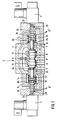
- valve 2 in FIG. 1 has the usual connections P (pump connection), T (tank connection), A (first working connection), B (second working connection, Y (control connection to the tank), as well as two electrical control magnets 4 and 6, with the working line A the left pilot valve side A 'is assigned and the working line B the right pilot valve side B'.
- the working part of the valve has a main control piston 8 in the usual way, which with two coaxial Piston collars 10, 12 is in one piece, the piston collar 10 being assigned to the working line A and the piston collar 12 being assigned to the working line B.
- the valve additionally has left and right centering pistons 22 and 24, which are each slidably fitted in the housing, and separate left and right actuating pistons 23 and 25.
- the left actuating piston 23 is freely movable in the centering piston 22 and in one A-side pilot chamber 14 can be pressurized.
- the right actuating piston 25 is freely movable in the centering piston 24 and can be pressurized in a B'-side pilot chamber 16.
- the main control piston 8 is held in its neutral central position by means of springs 18, 20, which act on the centering pistons 22, 24, when the pilot spaces 14, 16 are depressurized in the system in the event of pressure loss (spring centering).
- both pilot chambers 14, 16 With pressure in the system (port P) and non-energized control magnets 4, 6, both pilot chambers 14, 16 are pressurized, since they are connected to the pump port via the pilot spool valves 28, 29, the pistons of which are actuated by the preloaded springs 18, 20 P A and P B are connected.
- the two pistons of the pilot spool valves 28, 29 are axially drilled through to allow pressure compensation on both sides when shifting.
- the centering pistons 22, 24 are pressed by the pressure in the pilot control rooms 14, 16 against their stops in the valve housing 3 with great forces, since on their rear side the annular surface 34 is relieved of pressure to the respective T-connection.
- the main control piston 8 is thus pressure centered indirectly in a central position via the centering piston 22, 24.
- the control magnet 4 actuates the piston of the pilot valve 28 against the restoring force of the spring 18 with its plunger 26.
- the pilot chamber 14 is connected to Y and thus to the tank via an annular channel 32.
- the pilot control chamber 16 is pressurized by the restoring force of the spring 20 on the piston of the pilot control slide valve 29 via an annular channel 33 connected to P B.
- the actuating piston 25 therefore displaces the main control piston 8 against the centering flange 22 and the spring 18 supported thereon.
- Proportional to the stroke of the main control piston 8 an additional return force is generated in the spring 18, which is returned to the pilot valve 28 via the spring plate 30 and with the tappet force of the Control magnet 4 is compared.
- the ram force is in turn proportional to the given magnetic current.
- the position of the main control piston 8 as a function of the magnetic current (or the magnetic force) in a closed position control loop with spring return and force comparison on the pilot valve 28 is thus reached very precisely.
- the biasing force of the spring 18 predominates and the pilot control chamber 14 is pressurized again via the annular channel 32 of the pilot control slide valve 28. Since the total pressure force exerted on the main control piston 8 by the centering piston 22 with the actuating piston 23 contained therein is greater than the compressive force portion of the annular surface 34 by the compressive force of the sole actuating piston 25 on the opposite B ′ side (the centering piston 24 is in the housing stop), the main control piston becomes corresponding the reduction in force of the control magnet 4 is reset to a maximum of the housing stop of the centering piston 22.
- FIG. 2 shows an embodiment of a proportional directional control valve according to the invention with a single electrical control magnet for actuating the main control piston from the central position on only one side.
- This version is often used as a proportional throttle valve with only one flow direction.
- the B'-side pilot valve 29 is replaced by an end cap 38 which clamps the centering piston 24.
- the actuating piston 25 is constantly connected to the pilot control chamber 16 Pressure applied.
- the pilot control chamber 14 is pressurized via the pilot control valve 28 which is actuated by the prestressed spring 18 to the pressure connection P A.
- a centering piston 36 is slidably fitted in the valve housing and has a larger pressure area in the pilot control chamber 14 in relation to the actuating piston 25.
- FIG 3 shows a longitudinal section through the proportional directional control valve according to the invention with two additional 3/2-way seat valves integrated into the hydraulic pilot control of a valve side A 'or B', which are controlled by a higher-level machine control system in accordance with the safety requirements of the machine for releasing the main control piston position specified by the control magnet must be operated.
- a press closing movement can be carried out by opening the main control piston 8 in proportion to the actuation of the control magnet 4, a 3/2-way seat valve 39 must be actuated hydraulically with pressure via a relieved protective door valve 49 when the protective door 47 is closed.
- an electromagnet must have switched a 3/2-way seat valve 43 so that the tank port 35 of the pilot valve 28 is depressurized through the lines 40, 41 to the tank. Only then can the main control piston 8 move through the Take the control magnet 4 in the specified position and control the closing speed of the press cylinder.
- the safety valve which is additionally designed as an electromagnetically actuated 3/2-way seat valve 43, is connected in series with the valve 39.
- the tank connection 35 of the pilot valve 28 is also pressurized via connection 46 even when the 3/2-way seat valve 39 is actuated, so that the main control piston in the middle layer is pressure centered.
Landscapes
- Engineering & Computer Science (AREA)
- Physics & Mathematics (AREA)
- Fluid Mechanics (AREA)
- Mechanical Engineering (AREA)
- General Engineering & Computer Science (AREA)
- Servomotors (AREA)
- Fluid-Driven Valves (AREA)
- Fluid-Pressure Circuits (AREA)
- Vehicle Body Suspensions (AREA)
- Preparation Of Compounds By Using Micro-Organisms (AREA)
- Magnetically Actuated Valves (AREA)
Claims (8)
- Distributeur proportionnel avec réglage de position comprenant un piston principal (8) pilotable hydrauliquement moyennant deux robinets de pilotage (28, 29) amorcés par des aimants proportionnels (4, 6), avec rappel mécanique de la position du piston principal (8) sur le robinet de pilotage (28, 29) actionné, le piston principal occupant une position neutre, centrée par ressort, dans une cage de distributeur (3),
caractérisé en ce que le piston principal (8) est axialement réglable en position, grâce à deux pistons de centrage (22, 24) déplaçables chacun dans un guidage de cage, présentant chacun une section annulaire, ainsi que grâce à deux pistons de commande (23, 25) encastrés de manière déplaçable dans les pistons de centrage (22, 24), en ce que chacun des deux pistons de centrage (22, 24) comporte une butée axiale finale dans la cage (3) qui est disposée dans la cage (3) de telle sorte que le piston principal (8) se trouve dans sa position neutre lorsque les deux pistons de centrage (22, 24) se trouvent à leur butée finale, en ce que aux deux pistons de centrage (22, 24) sont associés des ressorts (18, 20) agissant dans le sens de leur butée finale, et en ce que les deux pistons de centrage (22, 24) de même que les deux pistons de commande (23, 25) développent des surfaces de pression agissant dans le sens de leur butée finale, dans un premier respectivement second espace de pilotage (14, 16) relié hydrauliquement au premier respectivement second robinet de pilotage (28, 29). - Distributeur proportionnel avec réglage de position selon la revendication 1,
caractérisé en ce que la surface totale active de pression des pistons de centrage (22, 24) et pistons de commande (23, 25) est dans un espace de pilotage (14, 16) respectivement plus grande que la surface active du piston de commande (23, 25) dans un autre espace de pilotage (14, 16), lorsque le piston principal (8) se trouve en dehors de sa position neutre. - Distributeur proportionnel avec réglage de position selon la revendication 1 ou 2,
caractérisé en ce qu'un ressort (18, 20) est enserré entre le robinet de pilotage (28, 29) et le piston de centrage (22, 24), ce qui a pour effet que la position du piston principal (8) est ramenée au robinet de pilotage (28, 29) de telle manière que par comparaison de force entre la force du ressort proportionnel à la position et la force de réglage de l'aimant proportionnel (4, 6), le robinet de pilotage règle, par l'intermédiaire de la pression de pilotage existant dans l'espace de pilotage (14, 16), la position du piston principal (8) proportionnellement à la force magnétique. - Distributeur proportionnel avec réglage de position selon la revendication 3,
caractérisé en ce que le ressort (18, 20) associé au robinet de pilotage (28, 29) définit, l'aimant proportionnel (4, 6) n'étant pas amorcé, une position de repos du robinet de pilotage (28, 29) centrée par ressort, dans laquelle l'espace de pilotage (14, 16) associé au robinet de pilotage est relié à un raccord de pression. - Distributeur proportionnel avec réglage de position selon l'une des revendications 1 à 4,
caractérisé par un distributeur à siège 3/2 (39) commandé hydrauliquement, comportant une première sortie (40), un premier raccord de réservoir (41) et un premier raccord de pression (42), et
par un distributeur à siège 3/2 (43) monté en amont et commandé électromagnétiquement comportant une deuxième sortie (44), un deuxième raccord de réservoir (45) et un deuxième raccord de pression (46),
la première sortie (40) étant reliée à un raccord de réservoir (35) du robinet de pilotage, le premier raccord de réservoir (41) étant relié à la deuxième sortie (44), le deuxième raccord de réservoir (45) étant relié à un raccord de réservoir exempt de pression, le deuxième raccord de pression (46) et le premier raccord de pression (42) étant reliés à un raccord de pompe pressurisé. - Distributeur proportionnel avec réglage de position comprenant un piston principal (8) pilotable hydrauliquement moyennant un robinet de pilotage (28, 29) amorcé par un aimant proportionnel (4), avec rappel mécanique de la position du piston principal (8) sur le robinet de pilotage (28, 29) actionné,
caractérisé en ce que le piston principal (8) est réglable en position dans la cage (3) moyennant un piston de centrage (36) axialement déplaçable et moyennant un piston de commande (25) situé axialement en face, une butée axiale finale étant associée au piston principal (8) dans la cage (3), en ce qu'un ressort (18) agissant dans le sens de ladite butée finale est associé au piston de centrage (36), en ce que le piston de centrage (36) développe, dans un premier espace de pilotage (14) relié hydrauliquement au robinet de pilotage (28), une première surface de pression agissant dans le sens de la butée finale, et en ce que le piston de commande (25) développe, dans un second espace de pilotage (16), une seconde surface de pression beaucoup plus petite et agissant dans le sens opposé, de sorte que lors de la pressurisation desdits espaces de pilotage, il y a centrage par pression du piston principal (8) vers la butée finale, moyennant le piston de centrage (36). - Distributeur proportionnel avec réglage de position selon la revendication 6,
caractérisé en ce que le piston de commande (25) est adapté de manière déplaçable dans une bride de centrage (24), ladite bride de centrage (24) étant fermement enserrée dans la cage, grâce à un capuchon (38), et constituant la butée finale pour le piston principal (8). - Distributeur proportionnel avec réglage de position selon la revendication 6 ou 7,
caractérisé en ce que le piston de centrage (36) est solidaire du piston principal (8).
Applications Claiming Priority (2)
| Application Number | Priority Date | Filing Date | Title |
|---|---|---|---|
| LU87640 | 1989-12-13 | ||
| LU87640A LU87640A1 (de) | 1989-12-13 | 1989-12-13 | Lagegeregeltes proportionalwegeventil |
Publications (2)
| Publication Number | Publication Date |
|---|---|
| EP0432606A1 EP0432606A1 (fr) | 1991-06-19 |
| EP0432606B1 true EP0432606B1 (fr) | 1995-08-09 |
Family
ID=19731201
Family Applications (1)
| Application Number | Title | Priority Date | Filing Date |
|---|---|---|---|
| EP19900123084 Expired - Lifetime EP0432606B1 (fr) | 1989-12-13 | 1990-12-03 | Distributeur proportionnel avec réglage de position |
Country Status (9)
| Country | Link |
|---|---|
| US (1) | US5144983A (fr) |
| EP (1) | EP0432606B1 (fr) |
| JP (1) | JP3193729B2 (fr) |
| AT (1) | ATE126325T1 (fr) |
| CA (1) | CA2031770C (fr) |
| DE (1) | DE59009502D1 (fr) |
| ES (1) | ES2077005T3 (fr) |
| FI (1) | FI98240C (fr) |
| LU (1) | LU87640A1 (fr) |
Families Citing this family (16)
| Publication number | Priority date | Publication date | Assignee | Title |
|---|---|---|---|---|
| LU88277A1 (de) * | 1993-05-27 | 1994-12-01 | Hydrolux Sarl | Vorgesteuertes Servoventil |
| US5366202A (en) * | 1993-07-06 | 1994-11-22 | Caterpillar Inc. | Displacement controlled hydraulic proportional valve |
| US5421545A (en) * | 1993-09-03 | 1995-06-06 | Caterpillar Inc. | Poppet valve with force feedback control |
| US5350152A (en) * | 1993-12-27 | 1994-09-27 | Caterpillar Inc. | Displacement controlled hydraulic proportional valve |
| DE19646446A1 (de) * | 1996-11-11 | 1998-05-14 | Rexroth Mannesmann Gmbh | Ventilanordnung |
| DE19900771B4 (de) * | 1999-01-12 | 2007-06-06 | Abb Patent Gmbh | Umschaltventil eines hydraulischen Antriebes für eine Betätigungseinrichtung, insbesondere ein Schaltgerät |
| US6769252B2 (en) | 2001-12-10 | 2004-08-03 | Caterpillar Inc | Fluid system having variable pressure relief |
| FR2847641B1 (fr) * | 2002-11-25 | 2006-06-30 | Snowstar S R L | Vanne de regulation a tiroir a au moins deux voies d'un nouveau type |
| DE10344458B3 (de) * | 2003-09-25 | 2005-05-25 | Festo Ag & Co. | Vorgesteuertes Mehrwegeventil |
| DE102010005228A1 (de) | 2010-01-21 | 2011-07-28 | Hydac Fluidtechnik GmbH, 66280 | Ventilvorrichtung |
| EP2711561B1 (fr) * | 2012-09-21 | 2019-08-28 | Danfoss Power Solutions Aps | Dispositif avec une soupape de commande électrohydraulique |
| DE102014019615A1 (de) * | 2014-12-30 | 2016-06-30 | Hydac Fluidtechnik Gmbh | Ventilvorrichtung |
| CN104633174A (zh) * | 2015-01-22 | 2015-05-20 | 天长市永鑫科技工贸有限公司 | 一种四通电磁阀 |
| JP5876185B1 (ja) * | 2015-08-27 | 2016-03-02 | 憲平 山路 | 電磁比例制御弁システム |
| CN105465083B (zh) * | 2016-01-25 | 2017-08-25 | 浙江大学城市学院 | 对称全桥双向型2d电液比例换向阀 |
| DE102017219645A1 (de) * | 2017-11-06 | 2019-05-09 | Zf Friedrichshafen Ag | Ventil, Hydrauliksystem und Kraftfahrzeuggetriebe |
Family Cites Families (9)
| Publication number | Priority date | Publication date | Assignee | Title |
|---|---|---|---|---|
| US4201116A (en) * | 1977-07-11 | 1980-05-06 | The Cessna Aircraft Company | Electro-hydraulic proportional control servo valve |
| DE2926547A1 (de) * | 1979-06-30 | 1981-01-15 | Reinhard Ing Grad Kucharzyk | Regel- und fernsteuerbares hydraulisches servoventil mit mechanischer rueckfuehrung und nothandbetaetigung |
| DE2932810A1 (de) * | 1979-08-13 | 1981-02-26 | Reinhard Ing Grad Kucharzyk | Elektrohydraulisches servoventil mit mechanischer rueckfuehrungsregelung |
| DE2938889A1 (de) * | 1979-09-26 | 1981-04-09 | Reinhard Ing.(grad.) 4050 Mönchengladbach Kucharzyk | Hydrodynamische regeleinrichtung zur druckmittel-stromregelung des steuerkolbens eines elktrohyraulischen servoventiles |
| DE2942754A1 (de) * | 1979-10-23 | 1981-05-07 | Reinhard Ing.(grad.) 4050 Mönchengladbach Kucharzyk | Elektrohydraulisches servoventil mit proportionaler druckmittel-stromregelung durch mechanische rueckfuehrung |
| DE3125386A1 (de) * | 1981-06-27 | 1983-01-13 | Robert Bosch Gmbh, 7000 Stuttgart | Elektro-hydraulische stelleinrichtung insbesondere zur fernsteuerung eines wegeventils |
| DE3527026A1 (de) * | 1985-07-27 | 1987-01-29 | Bosch Gmbh Robert | Elektrohydraulische stelleinheit |
| DE3708570C2 (de) * | 1987-03-17 | 1995-11-16 | Bosch Gmbh Robert | Elektrohydraulische Einrichtung zum Betätigen eines in einer Gehäusebohrung verschiebbaren kolbenartigen Teils |
| JP5833949B2 (ja) | 2012-02-27 | 2015-12-16 | 公益財団法人鉄道総合技術研究所 | トロリ線のオーバーラップ構造 |
-
1989
- 1989-12-13 LU LU87640A patent/LU87640A1/de unknown
-
1990
- 1990-12-03 AT AT90123084T patent/ATE126325T1/de not_active IP Right Cessation
- 1990-12-03 EP EP19900123084 patent/EP0432606B1/fr not_active Expired - Lifetime
- 1990-12-03 ES ES90123084T patent/ES2077005T3/es not_active Expired - Lifetime
- 1990-12-03 US US07/620,419 patent/US5144983A/en not_active Expired - Lifetime
- 1990-12-03 DE DE59009502T patent/DE59009502D1/de not_active Expired - Fee Related
- 1990-12-04 FI FI905981A patent/FI98240C/fi not_active IP Right Cessation
- 1990-12-07 CA CA002031770A patent/CA2031770C/fr not_active Expired - Fee Related
- 1990-12-11 JP JP40141090A patent/JP3193729B2/ja not_active Expired - Fee Related
Also Published As
| Publication number | Publication date |
|---|---|
| FI905981A0 (fi) | 1990-12-04 |
| ES2077005T3 (es) | 1995-11-16 |
| CA2031770A1 (fr) | 1991-06-14 |
| FI905981A7 (fi) | 1991-06-14 |
| JPH05312202A (ja) | 1993-11-22 |
| JP3193729B2 (ja) | 2001-07-30 |
| US5144983A (en) | 1992-09-08 |
| ATE126325T1 (de) | 1995-08-15 |
| DE59009502D1 (de) | 1995-09-14 |
| FI98240C (fi) | 1997-05-12 |
| FI98240B (fi) | 1997-01-31 |
| LU87640A1 (de) | 1990-03-13 |
| EP0432606A1 (fr) | 1991-06-19 |
| CA2031770C (fr) | 2001-05-01 |
Similar Documents
| Publication | Publication Date | Title |
|---|---|---|
| EP0628731B1 (fr) | Servo-soupape asservie | |
| EP0623754B1 (fr) | Système hydraulique de contrÔle | |
| EP0432606A1 (fr) | Distributeur proportionnel avec réglage de position | |
| EP2769129B1 (fr) | Étage de pilotage d'une soupape hydraulique haute pression à commande proportionnelle | |
| EP0083688B1 (fr) | Soupape d'étranglement proportionnelle pilotée électro-hydrauliquement | |
| DE69623958T2 (de) | Antriebsvorrichtung für einen hydraulischen motor | |
| EP0342410A2 (fr) | Soupape de sûreté | |
| DE3329734C2 (fr) | ||
| EP0370131B1 (fr) | Vanne pilotée à trois voies | |
| EP2807406B1 (fr) | Ensemble permettant de commander un vérin de changement de vitesse à double effet d'un ensemble de changement de vitesse d'une transmission automatique d'un véhicule automobile | |
| DE3125386A1 (de) | Elektro-hydraulische stelleinrichtung insbesondere zur fernsteuerung eines wegeventils | |
| EP1203161B1 (fr) | Soupape de securite de presse | |
| US5236015A (en) | Position-controlled proportional directional valve | |
| DE9310932U1 (de) | Elektrohydraulische Steuervorrichtung | |
| EP0209817A1 (fr) | Amplificateur et modulateur de pression | |
| EP0074419B1 (fr) | Disjoncteur électrique à haut pouvoir de coupure ayant un dispositif de commande hydraulique | |
| EP0376115A1 (fr) | Valve hydraulique de sécurité | |
| DE10107164C1 (de) | Proportional-Wegemagnetventil | |
| DE3110210C2 (fr) | ||
| DE3736750C2 (fr) | ||
| EP0376023B1 (fr) | Soupape électrohydraulique proportionnelle | |
| DE2161503A1 (de) | Druckmittelbetätigte Einrichtung zur Steuerung eines doppeltwirkenden Arbeitszylinders | |
| DE4417204B4 (de) | Vorgesteuertes Servoventil | |
| DE4405143C2 (de) | Elektrohydraulisches Proportionalwegeventil | |
| DE4418514A1 (de) | Elektrohydraulisches Wegeventil |
Legal Events
| Date | Code | Title | Description |
|---|---|---|---|
| PUAI | Public reference made under article 153(3) epc to a published international application that has entered the european phase |
Free format text: ORIGINAL CODE: 0009012 |
|
| AK | Designated contracting states |
Kind code of ref document: A1 Designated state(s): AT CH DE ES FR GB IT LI SE |
|
| 17P | Request for examination filed |
Effective date: 19911021 |
|
| 17Q | First examination report despatched |
Effective date: 19930310 |
|
| GRAA | (expected) grant |
Free format text: ORIGINAL CODE: 0009210 |
|
| AK | Designated contracting states |
Kind code of ref document: B1 Designated state(s): AT CH DE ES FR GB IT LI SE |
|
| REF | Corresponds to: |
Ref document number: 126325 Country of ref document: AT Date of ref document: 19950815 Kind code of ref document: T |
|
| REF | Corresponds to: |
Ref document number: 59009502 Country of ref document: DE Date of ref document: 19950914 |
|
| GBT | Gb: translation of ep patent filed (gb section 77(6)(a)/1977) |
Effective date: 19950830 |
|
| ET | Fr: translation filed | ||
| ITF | It: translation for a ep patent filed | ||
| REG | Reference to a national code |
Ref country code: ES Ref legal event code: FG2A Ref document number: 2077005 Country of ref document: ES Kind code of ref document: T3 |
|
| PLBE | No opposition filed within time limit |
Free format text: ORIGINAL CODE: 0009261 |
|
| STAA | Information on the status of an ep patent application or granted ep patent |
Free format text: STATUS: NO OPPOSITION FILED WITHIN TIME LIMIT |
|
| 26N | No opposition filed | ||
| REG | Reference to a national code |
Ref country code: GB Ref legal event code: IF02 |
|
| PGFP | Annual fee paid to national office [announced via postgrant information from national office to epo] |
Ref country code: FR Payment date: 20031113 Year of fee payment: 14 |
|
| PGFP | Annual fee paid to national office [announced via postgrant information from national office to epo] |
Ref country code: DE Payment date: 20031115 Year of fee payment: 14 |
|
| PGFP | Annual fee paid to national office [announced via postgrant information from national office to epo] |
Ref country code: GB Payment date: 20031118 Year of fee payment: 14 |
|
| PGFP | Annual fee paid to national office [announced via postgrant information from national office to epo] |
Ref country code: AT Payment date: 20031119 Year of fee payment: 14 |
|
| PGFP | Annual fee paid to national office [announced via postgrant information from national office to epo] |
Ref country code: CH Payment date: 20031124 Year of fee payment: 14 |
|
| PGFP | Annual fee paid to national office [announced via postgrant information from national office to epo] |
Ref country code: SE Payment date: 20031219 Year of fee payment: 14 |
|
| PGFP | Annual fee paid to national office [announced via postgrant information from national office to epo] |
Ref country code: ES Payment date: 20040108 Year of fee payment: 14 |
|
| PG25 | Lapsed in a contracting state [announced via postgrant information from national office to epo] |
Ref country code: GB Free format text: LAPSE BECAUSE OF NON-PAYMENT OF DUE FEES Effective date: 20041203 Ref country code: AT Free format text: LAPSE BECAUSE OF NON-PAYMENT OF DUE FEES Effective date: 20041203 |
|
| PG25 | Lapsed in a contracting state [announced via postgrant information from national office to epo] |
Ref country code: SE Free format text: LAPSE BECAUSE OF NON-PAYMENT OF DUE FEES Effective date: 20041204 Ref country code: ES Free format text: LAPSE BECAUSE OF NON-PAYMENT OF DUE FEES Effective date: 20041204 |
|
| PG25 | Lapsed in a contracting state [announced via postgrant information from national office to epo] |
Ref country code: LI Free format text: LAPSE BECAUSE OF NON-PAYMENT OF DUE FEES Effective date: 20041231 Ref country code: CH Free format text: LAPSE BECAUSE OF NON-PAYMENT OF DUE FEES Effective date: 20041231 |
|
| PG25 | Lapsed in a contracting state [announced via postgrant information from national office to epo] |
Ref country code: DE Free format text: LAPSE BECAUSE OF NON-PAYMENT OF DUE FEES Effective date: 20050701 |
|
| GBPC | Gb: european patent ceased through non-payment of renewal fee |
Effective date: 20041203 |
|
| EUG | Se: european patent has lapsed | ||
| REG | Reference to a national code |
Ref country code: CH Ref legal event code: PL |
|
| PG25 | Lapsed in a contracting state [announced via postgrant information from national office to epo] |
Ref country code: FR Free format text: LAPSE BECAUSE OF NON-PAYMENT OF DUE FEES Effective date: 20050831 |
|
| REG | Reference to a national code |
Ref country code: FR Ref legal event code: ST |
|
| PG25 | Lapsed in a contracting state [announced via postgrant information from national office to epo] |
Ref country code: IT Free format text: LAPSE BECAUSE OF NON-PAYMENT OF DUE FEES;WARNING: LAPSES OF ITALIAN PATENTS WITH EFFECTIVE DATE BEFORE 2007 MAY HAVE OCCURRED AT ANY TIME BEFORE 2007. THE CORRECT EFFECTIVE DATE MAY BE DIFFERENT FROM THE ONE RECORDED. Effective date: 20051203 |
|
| REG | Reference to a national code |
Ref country code: ES Ref legal event code: FD2A Effective date: 20041204 |