EP0432673A2 - Dispositif mobile pour produire des mélanges actifs sur base de l'eau - Google Patents
Dispositif mobile pour produire des mélanges actifs sur base de l'eau Download PDFInfo
- Publication number
- EP0432673A2 EP0432673A2 EP90123634A EP90123634A EP0432673A2 EP 0432673 A2 EP0432673 A2 EP 0432673A2 EP 90123634 A EP90123634 A EP 90123634A EP 90123634 A EP90123634 A EP 90123634A EP 0432673 A2 EP0432673 A2 EP 0432673A2
- Authority
- EP
- European Patent Office
- Prior art keywords
- active substance
- container
- liquid active
- mixing container
- water
- Prior art date
- Legal status (The legal status is an assumption and is not a legal conclusion. Google has not performed a legal analysis and makes no representation as to the accuracy of the status listed.)
- Granted
Links
Images
Classifications
-
- G—PHYSICS
- G05—CONTROLLING; REGULATING
- G05D—SYSTEMS FOR CONTROLLING OR REGULATING NON-ELECTRIC VARIABLES
- G05D11/00—Control of flow ratio
- G05D11/02—Controlling ratio of two or more flows of fluid or fluent material
- G05D11/13—Controlling ratio of two or more flows of fluid or fluent material characterised by the use of electric means
- G05D11/131—Controlling ratio of two or more flows of fluid or fluent material characterised by the use of electric means by measuring the values related to the quantity of the individual components
- G05D11/132—Controlling ratio of two or more flows of fluid or fluent material characterised by the use of electric means by measuring the values related to the quantity of the individual components by controlling the flow of the individual components
-
- A—HUMAN NECESSITIES
- A01—AGRICULTURE; FORESTRY; ANIMAL HUSBANDRY; HUNTING; TRAPPING; FISHING
- A01C—PLANTING; SOWING; FERTILISING
- A01C23/00—Distributing devices specially adapted for liquid manure or other fertilising liquid, including ammonia, e.g. transport tanks or sprinkling wagons
- A01C23/04—Distributing under pressure; Distributing mud; Adaptation of watering systems for fertilising-liquids
- A01C23/042—Adding fertiliser to watering systems
-
- A—HUMAN NECESSITIES
- A01—AGRICULTURE; FORESTRY; ANIMAL HUSBANDRY; HUNTING; TRAPPING; FISHING
- A01M—CATCHING, TRAPPING OR SCARING OF ANIMALS; APPARATUS FOR THE DESTRUCTION OF NOXIOUS ANIMALS OR NOXIOUS PLANTS
- A01M7/00—Special adaptations or arrangements of liquid-spraying apparatus for purposes covered by this subclass
- A01M7/0089—Regulating or controlling systems
- A01M7/0092—Adding active material
-
- B—PERFORMING OPERATIONS; TRANSPORTING
- B01—PHYSICAL OR CHEMICAL PROCESSES OR APPARATUS IN GENERAL
- B01F—MIXING, e.g. DISSOLVING, EMULSIFYING OR DISPERSING
- B01F25/00—Flow mixers; Mixers for falling materials, e.g. solid particles
- B01F25/30—Injector mixers
- B01F25/31—Injector mixers in conduits or tubes through which the main component flows
- B01F25/313—Injector mixers in conduits or tubes through which the main component flows wherein additional components are introduced in the centre of the conduit
- B01F25/3131—Injector mixers in conduits or tubes through which the main component flows wherein additional components are introduced in the centre of the conduit with additional mixing means other than injector mixers, e.g. screens, baffles or rotating elements
-
- B—PERFORMING OPERATIONS; TRANSPORTING
- B01—PHYSICAL OR CHEMICAL PROCESSES OR APPARATUS IN GENERAL
- B01F—MIXING, e.g. DISSOLVING, EMULSIFYING OR DISPERSING
- B01F35/00—Accessories for mixers; Auxiliary operations or auxiliary devices; Parts or details of general application
- B01F35/80—Forming a predetermined ratio of the substances to be mixed
- B01F35/83—Forming a predetermined ratio of the substances to be mixed by controlling the ratio of two or more flows, e.g. using flow sensing or flow controlling devices
-
- B—PERFORMING OPERATIONS; TRANSPORTING
- B01—PHYSICAL OR CHEMICAL PROCESSES OR APPARATUS IN GENERAL
- B01F—MIXING, e.g. DISSOLVING, EMULSIFYING OR DISPERSING
- B01F25/00—Flow mixers; Mixers for falling materials, e.g. solid particles
- B01F2025/91—Direction of flow or arrangement of feed and discharge openings
- B01F2025/918—Counter current flow, i.e. flows moving in opposite direction and colliding
Definitions
- the invention relates to a mobile device for producing a solution, in particular intended for spraying, consisting of water and at least one liquid active substance, according to the preamble of claim 1.
- a solution consisting of water and at least one liquid active ingredient plays an important role in agriculture, for example, when spraying crop protection agents.
- the solution to be sprayed must have a precisely prescribed mixing ratio between water and liquid active substance.
- the exact maintenance of the mixing ratio is usually achieved by preparing a sufficiently large amount of solution in a tank before spraying the solution by mixing a certain amount of water with a corresponding amount of liquid active ingredient.
- a solution can be produced with exact adherence to a predetermined mixing ratio, but this method has the disadvantage that, on the one hand, the preparation of the solution is a laborious and lengthy affair and, on the other hand, that exactly the one required when the solution is mixed Amount of solution must be known.
- the mixed amount of solution does not exactly match the amount of solution actually required for spraying, so that either a solution has to be prepared again or the excess solution has to be removed in a suitable manner while accepting an unnecessary environmental impact.
- the spraying of solutions with changing concentrations or compositions is practically not feasible in this way.
- This device has a mixing container, to which water is continuously fed in accordance with the current solution requirement. Before the water reaches the mixing container, it drives a hydraulic piston pump, which draws the liquid active substance from an active substance container and pumps it into the mixing container. The non-continuous supply of liquid active substance into the mixing container, however, causes a fluctuating concentration of the solution to be sprayed.
- the invention has for its object to develop a device according to the preamble of claim 1 such that a quantity of solution with constant concentration can only be produced in a simple manner corresponding to the current need.
- the liquid active substance is thus conveyed from the active substance container to the mixing container by means of compressed air, in that the active substance container is designed as a pressure container and is subjected to constant pressure.
- the constant pressure in the active substance container enables a constantly constant amount of liquid active substance to be conveyed to the mixing container. So is in the mixing tank a solution with constant concentration can be produced.
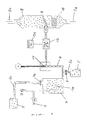
- the device shown in FIG. 1 and described in more detail below is part of a mobile spray device with a water tank, such as, for example, a mobile crop protection sprayer which is pulled by a tractor and thereby sprays a crop protection solution.
- a mobile spray device with a water tank, such as, for example, a mobile crop protection sprayer which is pulled by a tractor and thereby sprays a crop protection solution.
- an active substance container 4 contains a liquid active substance X.
- a filler lock 4a of the active substance container 4 can be closed in an airtight manner by a closure lid, not shown.
- a compressed air supply line 1 projecting from the outside into the interior of the active substance container 4 has a nozzle la at its end.
- an adjustable pressure reducing valve 2 and an air pressure indicator device 3, optionally with a pressure limiting valve, are provided on the compressed air supply line 1.
- the active substance container 4 is connected via an active substance line 7 to a cylindrical mixing container 9.
- the mixing container 9 has a water supply opening 9a for supplying water O from the water tank (not shown) and a discharge opening 9b for discharging the water and the water liquid active ingredient formed on.
- a cylindrical baffle 10 downstream of the angle nozzle 8 which has inclined slots on its outer surface.
- a flow rate control valve in the form of a needle valve 11 and a flow rate meter 12 with a display device 12a are provided on the active ingredient line 7 by an actuator in the form of an electric motor M.
- a tank hose 5a connected to a storage tank 5 can be attached to the filler lock 4a of the active substance container 4 after the closure cap (not shown) has been removed.
- the active substance line 7 has a downward-reaching emptying nozzle 7a with a shut-off valve 6. After the shut-off valve 6, the tank hose 5a connected to the storage tank 5 can be attached to the emptying nozzle 7a.
- a solution consisting of the water O and the liquid active substance X is prepared in the mixing container 9.
- the liquid active substance X passes from the active substance container 4 via the active substance line 7 and the angled nozzle 8 into the mixing container 9.
- the angled nozzle causes the liquid active substance X to form a fan is introduced into the interior of the mixing container 9 in such a way that a largely uniform feed of the liquid active substance results over the entire cross section of the mixing container 9. This ensures that the liquid active ingredient can mix evenly with the water introduced via the water supply opening 9a in cross and countercurrent.
- the mixed liquids are passed on the side past the bluff body 10 on their way to the discharge opening 9b, whereby they are set into a rotating movement which causes uniform mixing.
- the solution leaving the mixing container 9 via the discharge opening 9b therefore has an extremely uniform concentration.
- the liquid active substance is conveyed out of the active substance container 4 by means of compressed air.
- compressed air is fed via the compressed air supply line 1, for example from a compressed air system of a tractor or a separate air pressure recovery system, into the active substance container 4.
- the nozzle la gives the compressed air supply line 1 a function as a mixing tube and causes the liquid active substance in the active substance container 4 to be constantly mixed up by the circularly introduced compressed air.
- the pressure reducing valve 2 in the compressed air supply line 1 the pressure inside the active substance container 4 can be adjusted to a predetermined value, so that the amount of liquid active substance transported per unit time to the mixing container 9 can be kept constant. If the pressure inside the active substance container 4 exceeds a predetermined value, the excess pressure can be diverted to the outside through the limiting valve on the air pressure display device 3.
- the quantity of liquid active substance X transported through the active substance line 7 to the mixing container 9 is adjusted by the flow rate control valve 11 which can be adjusted by means of the electric motor M. With the help of the flow meter 12, the amount of liquid active substance transported per unit of time is measured. The measurement of the flow rate is carried out by counting magnetic pulses which are generated by an impeller, which is set into a rotary movement by the flowing liquid active substance in accordance with the flow rate.
- the flow rate measured by the flow meter 12 is displayed by the display device 12a. An operator is thus in a position to adjust the flow control valve 11 in such a way that the mixing container per unit time is controlled by actuating the servomotor M in a targeted manner 9 transported amount of liquid active substance assumes a desired value.
- the flow rate measured by the flow rate counter 12 can, however, also be used directly for an automatic control of the flow rate.
- a control device not shown, is provided, for example in the form of an on-board computer, which is connected to the electric motor M for setting the flow rate control valve 11 and the flow rate meter 12 and an input device, such as a keyboard, for entering the value of a desired per unit of time Flow rate has.
- the flow rate control valve 11 can be adjusted via the electric motor M such that the desired flow rate value entered via the input device is constantly and exactly maintained.
- the control device can also be connected to the pressure reducing valve 2, so that, if necessary, by adjusting this valve, the pressure in the active substance container 4 responsible for the transport of the liquid active substance to the mixing container 9 can also be set.
- the control device can ensure that a constant amount of liquid active ingredient is transported to the mixing container 9 per unit of time. Provided that the water from the water tank also reaches the mixing container with a constant amount per unit of time, a solution consisting of water and liquid active ingredient can be produced with a mixing ratio that is extremely constant over time. With a constant driving speed of the spray device, this results in a constant amount of the solution sprayed per unit area.
- control device is additionally supplied with a signal indicating the amount of water entering the mixing container per unit of time
- the control device can also do so be designed so that not the amount of liquid active ingredient to be transported to the mixing container has to be entered, but a desired mixing ratio of the solution.
- the amount of water supplied to the mixing container depends on the driving speed, for example of a crop protection agent spraying device pulled by a tractor, it can be achieved in this way that a constant amount of solution with constant concentration is sprayed per unit area. In this case, it is no longer necessary to exactly maintain the speed of 8 km / h that is usually aimed for when spraying pesticide solutions.
- the active substance container 4 is filled with the liquid active substance from the storage tank 5 via the tank hose 5a and the filling lock 4a in the depressurized state of the active substance container.
- the tank hose 5a fastened to the storage tank 5 is attached to the filling lock 4a after removal of the closure cap and then the liquid active substance is transferred from the storage tank 5 into the active substance container.
- this residual amount can be drained off into the storage tank 5 via the emptying nozzle 7a and the tank hose 5a.
- the tank hose 5a attached to the storage tank 5 is attached to the emptying nozzle 7a, and after opening the shut-off valve 6, the liquid active substance runs off into the storage tank 5.
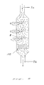
- FIG. 2 shows a modified mixing container which differs from the mixing container 9 shown in FIG. 1 in that it has a plurality of angle nozzles 8 which are offset with respect to one another with respect to the flow direction of the water in the mixing container.
- Each of these nozzles can each be connected to a device for conveying a liquid active substance described above into the mixing container, and thus it is simple to switch on or off the supply of individual liquid active substances to the mixing container possible to produce solutions from more than two liquids or successively differently composed solutions.
Landscapes
- Life Sciences & Earth Sciences (AREA)
- Engineering & Computer Science (AREA)
- Chemical Kinetics & Catalysis (AREA)
- Chemical & Material Sciences (AREA)
- Environmental Sciences (AREA)
- Insects & Arthropods (AREA)
- Wood Science & Technology (AREA)
- Automation & Control Theory (AREA)
- Soil Sciences (AREA)
- General Physics & Mathematics (AREA)
- Physics & Mathematics (AREA)
- Pest Control & Pesticides (AREA)
- Water Supply & Treatment (AREA)
- Zoology (AREA)
- Catching Or Destruction (AREA)
- Accessories For Mixers (AREA)
- Cosmetics (AREA)
- Nozzles (AREA)
- Agricultural Chemicals And Associated Chemicals (AREA)
- Pharmaceuticals Containing Other Organic And Inorganic Compounds (AREA)
Applications Claiming Priority (4)
| Application Number | Priority Date | Filing Date | Title |
|---|---|---|---|
| DE8914599U DE8914599U1 (de) | 1989-12-12 | 1989-12-12 | Vorrichtung zum genauen und kontrolliertem Einspeisen und Vermischen von chemischen Flüssigkeiten in Wasser für Pflanzenschutz |
| DE8914599U | 1989-12-12 | ||
| DE9014034U | 1990-10-09 | ||
| DE9014034U DE9014034U1 (de) | 1989-12-12 | 1990-10-09 | Fahrbare Vorrichtung zum Herstellen einer insbesondere zum Versprühen bestimmten, aus Wasser und mindestens einem flüssigen Wirkstoff bestehenden Lösung |
Publications (3)
| Publication Number | Publication Date |
|---|---|
| EP0432673A2 true EP0432673A2 (fr) | 1991-06-19 |
| EP0432673A3 EP0432673A3 (en) | 1992-09-16 |
| EP0432673B1 EP0432673B1 (fr) | 1995-08-23 |
Family
ID=25955620
Family Applications (1)
| Application Number | Title | Priority Date | Filing Date |
|---|---|---|---|
| EP90123634A Expired - Lifetime EP0432673B1 (fr) | 1989-12-12 | 1990-12-08 | Dispositif mobile pour produire des mélanges actifs sur base de l'eau |
Country Status (3)
| Country | Link |
|---|---|
| EP (1) | EP0432673B1 (fr) |
| AT (1) | ATE126663T1 (fr) |
| DE (2) | DE9014034U1 (fr) |
Cited By (3)
| Publication number | Priority date | Publication date | Assignee | Title |
|---|---|---|---|---|
| EP0521539A1 (fr) * | 1991-07-04 | 1993-01-07 | Kaj Aage Bräuner | Installation pour délivrer un mélange d'eau d'engrais dans un système d'irrigation |
| CN103744444A (zh) * | 2014-01-22 | 2014-04-23 | 无锡建苑自动控制工程研究设计有限公司 | 水煤浆跟踪配料控制系统 |
| CN110149878A (zh) * | 2019-05-22 | 2019-08-23 | 杨弃 | 一种水肥一体化智能精准灌溉装置 |
Families Citing this family (9)
| Publication number | Priority date | Publication date | Assignee | Title |
|---|---|---|---|---|
| DE4116707A1 (de) * | 1991-05-22 | 1992-11-26 | Carl Epple Druckfarbenfabrik G | Verfahren und farbzufuhrvorrichtung zur zufuhr der druckfarbe zu einem druckmaschinen-druckwerk mit getrennter zufuhr von druckfarbe und trocken- bzw. reaktionsstoff |
| US5851407A (en) * | 1996-12-04 | 1998-12-22 | Applied Process Technolgy, Inc. | Process and apparatus for oxidation of contaminants in water |
| EP1021377B1 (fr) * | 1997-08-08 | 2003-01-08 | Applied Process Technology, Inc. | Procede et appareil de decontamination d'eau |
| US6024882A (en) * | 1997-08-08 | 2000-02-15 | Applied Process Technology, Inc. | Process and apparatus for water decontamination |
| IT1391171B1 (it) * | 2008-08-12 | 2011-11-18 | Ifa Internat Fluid Ass | Impianto di irrigazione multi funzionale con sistema di svuotamento e pulizia ad aria compressa |
| DE102014012433A1 (de) * | 2014-08-26 | 2016-03-03 | Markus Kress | Vorrichtung zur Zumischung eines flüssigen Substrates und Vorrichtung zum Versprühen einer Flüssigkeit |
| CN104770351A (zh) * | 2015-03-26 | 2015-07-15 | 淮南东正电子科技有限公司 | 一种即混即用混药装置 |
| CN108966783A (zh) * | 2018-06-13 | 2018-12-11 | 江苏大学 | 一种实现水肥药精确比率的混施方法 |
| CN113273558B (zh) * | 2021-04-20 | 2022-05-20 | 江苏大学 | 一种羟基自由基溶液高地隙喷杆喷雾机及其使用方法 |
Family Cites Families (8)
| Publication number | Priority date | Publication date | Assignee | Title |
|---|---|---|---|---|
| US1967799A (en) * | 1933-07-01 | 1934-07-24 | Rudolph W Wittemann | Carbonating apparatus |
| FR1501922A (fr) * | 1966-09-29 | 1967-11-18 | Amorçage et alimentation des pulvérisateurs pneumatiques de liquides | |
| FR2148823A5 (fr) * | 1971-07-30 | 1973-03-23 | Charvoz Jean Pierre | |
| GB1407588A (en) * | 1971-08-17 | 1975-09-24 | Fisons Ltd | Sprayer |
| NL7607981A (en) * | 1976-07-19 | 1978-01-23 | Franz Colle | Chemical injection spray system - is pressurised by gas in receiver and injects via metering port into carrier liq. |
| DE3540923A1 (de) * | 1985-11-19 | 1987-05-21 | Amazonen Werke Dreyer H | Landwirtschaftliche feldspritze |
| NZ227406A (en) * | 1987-12-31 | 1990-04-26 | Nomix Mfg Co Ltd | Spraying apparatus with calibration of sprayer pump; reversing pump returns calibrating liquid to source |
| SE460395B (sv) * | 1988-04-18 | 1989-10-09 | Bengt Samuelsson | Anordning foer blandning och utmatning av vaetskor |
-
1990
- 1990-10-09 DE DE9014034U patent/DE9014034U1/de not_active Expired - Lifetime
- 1990-12-08 DE DE59009555T patent/DE59009555D1/de not_active Expired - Fee Related
- 1990-12-08 EP EP90123634A patent/EP0432673B1/fr not_active Expired - Lifetime
- 1990-12-08 AT AT90123634T patent/ATE126663T1/de not_active IP Right Cessation
Cited By (4)
| Publication number | Priority date | Publication date | Assignee | Title |
|---|---|---|---|---|
| EP0521539A1 (fr) * | 1991-07-04 | 1993-01-07 | Kaj Aage Bräuner | Installation pour délivrer un mélange d'eau d'engrais dans un système d'irrigation |
| CN103744444A (zh) * | 2014-01-22 | 2014-04-23 | 无锡建苑自动控制工程研究设计有限公司 | 水煤浆跟踪配料控制系统 |
| CN110149878A (zh) * | 2019-05-22 | 2019-08-23 | 杨弃 | 一种水肥一体化智能精准灌溉装置 |
| CN110149878B (zh) * | 2019-05-22 | 2022-01-28 | 湛江市佳德科技有限公司 | 一种水肥一体化智能精准灌溉装置 |
Also Published As
| Publication number | Publication date |
|---|---|
| EP0432673A3 (en) | 1992-09-16 |
| EP0432673B1 (fr) | 1995-08-23 |
| DE9014034U1 (de) | 1991-01-03 |
| DE59009555D1 (de) | 1995-09-28 |
| ATE126663T1 (de) | 1995-09-15 |
Similar Documents
| Publication | Publication Date | Title |
|---|---|---|
| DE60119637T2 (de) | Zerstäubungsanordnung insbesondere für die landwirtschaftliche Verwendung | |
| DE3331413C1 (de) | Landwirtschaftliches Geraet zum dosierten Ausbringen von Fluessigkeiten | |
| DE3879446T2 (de) | Geraet zum ausgeben von fluessigkeiten. | |
| DE3908963C2 (de) | Gerät zum Applizieren von Pflanzenbehandlungsmitteln unter geschwindigkeitsabhängiger Direkteinspeisung | |
| EP2022329A2 (fr) | Dispositif de pulvérisation mobile doté d'une tige de pulvérisation et procédé de réglage de ses buses de pulvérisation | |
| EP0432673B1 (fr) | Dispositif mobile pour produire des mélanges actifs sur base de l'eau | |
| EP0385926B1 (fr) | Dispositif pour distribuer des substances protégeant les plantes | |
| EP3167712B1 (fr) | Dispositif de pulvérisation de liquides et procédé de pulvérisation de liquides | |
| DE102010023380B4 (de) | Wiederbefüllbares und selbstdosierendes Gebindesystem für Pflanzenschutzmittel mit integrierter, hydraulisch von außen angetriebener Dosierpumpe | |
| DE8915850U1 (de) | Einrichtung zum dosierten Auftragen eines flüssigen Bindemittels, insbesondere von Bitumen, auf eine Oberfläche | |
| WO2019001939A1 (fr) | Unité de rejet pour le rejet d'un liquide final au ratio de mélange final défini | |
| EP1932424B1 (fr) | Dispositif de pulvérisation | |
| DE3038334C2 (fr) | ||
| DE4123047A1 (de) | Verfahren und vorrichtung zum mischen von getraenkekomponenten | |
| EP0079018A1 (fr) | Appareil pour répandre du lisier | |
| DE102013107445A1 (de) | Landwirtschaftliche Feldspritze | |
| DE2502407B2 (de) | Dosiervorrichtung für fahrbare Landmaschinen zum Zerstäuben von Flüssigkeiten | |
| DE3417372C2 (fr) | ||
| EP0357929A2 (fr) | Procédé et dispositif de dosage d'accélérateurs de prise pour l'application de béton projeté | |
| DE1607391B1 (de) | Vorrichtung zur Fluessigkeitsmengensteuerung bei Schaedlingsbekaempfungsspritzen und -Spruehern | |
| DE4413249A1 (de) | Verfahren zum Aufspritzen von aus Farbmengen zusammengesetzten Farbmischungen auf Unterlagen, insbesondere von aus mehreren Komponenten zusammengesetzten Farben, und Gerät zur Durchführung des Verfahrens | |
| DE102006045109A1 (de) | Vorrichtung und Verfahren zur Dosierung von Calciumhypochlorit in ein wässriges System | |
| DE3103686C2 (fr) | ||
| DE2523374A1 (de) | Vorrichtung zur kontinuierlichen herstellung von angemachtem moertel | |
| AT523682B1 (de) | Transporteinrichtung und Dosiermodul |
Legal Events
| Date | Code | Title | Description |
|---|---|---|---|
| PUAI | Public reference made under article 153(3) epc to a published international application that has entered the european phase |
Free format text: ORIGINAL CODE: 0009012 |
|
| AK | Designated contracting states |
Kind code of ref document: A2 Designated state(s): AT BE CH DE DK ES FR GB GR IT LI LU NL SE |
|
| PUAL | Search report despatched |
Free format text: ORIGINAL CODE: 0009013 |
|
| AK | Designated contracting states |
Kind code of ref document: A3 Designated state(s): AT BE CH DE DK ES FR GB GR IT LI LU NL SE |
|
| 17P | Request for examination filed |
Effective date: 19921104 |
|
| 17Q | First examination report despatched |
Effective date: 19931210 |
|
| GRAA | (expected) grant |
Free format text: ORIGINAL CODE: 0009210 |
|
| AK | Designated contracting states |
Kind code of ref document: B1 Designated state(s): AT BE CH DE DK ES FR GB GR IT LI LU NL SE |
|
| PG25 | Lapsed in a contracting state [announced via postgrant information from national office to epo] |
Ref country code: IT Free format text: LAPSE BECAUSE OF FAILURE TO SUBMIT A TRANSLATION OF THE DESCRIPTION OR TO PAY THE FEE WITHIN THE PRE;WARNING: LAPSES OF ITALIAN PATENTS WITH EFFECTIVE DATE BEFORE 2007 MAY HAVE OCCURRED AT ANY TIME BEFORE 2007. THE CORRECT EFFECTIVE DATE MAY BE DIFFERENT FROM THE ONE RECORDED.SCRIBED TIME-LIMIT Effective date: 19950823 Ref country code: DK Effective date: 19950823 Ref country code: ES Free format text: THE PATENT HAS BEEN ANNULLED BY A DECISION OF A NATIONAL AUTHORITY Effective date: 19950823 Ref country code: GR Free format text: LAPSE BECAUSE OF FAILURE TO SUBMIT A TRANSLATION OF THE DESCRIPTION OR TO PAY THE FEE WITHIN THE PRESCRIBED TIME-LIMIT Effective date: 19950823 Ref country code: BE Effective date: 19950823 Ref country code: NL Free format text: LAPSE BECAUSE OF NON-PAYMENT OF DUE FEES Effective date: 19950823 |
|
| REF | Corresponds to: |
Ref document number: 126663 Country of ref document: AT Date of ref document: 19950915 Kind code of ref document: T |
|
| REF | Corresponds to: |
Ref document number: 59009555 Country of ref document: DE Date of ref document: 19950928 |
|
| PG25 | Lapsed in a contracting state [announced via postgrant information from national office to epo] |
Ref country code: SE Effective date: 19951123 |
|
| GBT | Gb: translation of ep patent filed (gb section 77(6)(a)/1977) |
Effective date: 19951031 |
|
| ET | Fr: translation filed | ||
| PG25 | Lapsed in a contracting state [announced via postgrant information from national office to epo] |
Ref country code: AT Effective date: 19951208 |
|
| PG25 | Lapsed in a contracting state [announced via postgrant information from national office to epo] |
Ref country code: LU Free format text: LAPSE BECAUSE OF NON-PAYMENT OF DUE FEES Effective date: 19951231 Ref country code: LI Effective date: 19951231 Ref country code: CH Effective date: 19951231 |
|
| NLV1 | Nl: lapsed or annulled due to failure to fulfill the requirements of art. 29p and 29m of the patents act | ||
| PLBE | No opposition filed within time limit |
Free format text: ORIGINAL CODE: 0009261 |
|
| STAA | Information on the status of an ep patent application or granted ep patent |
Free format text: STATUS: NO OPPOSITION FILED WITHIN TIME LIMIT |
|
| 26N | No opposition filed | ||
| REG | Reference to a national code |
Ref country code: CH Ref legal event code: PL |
|
| REG | Reference to a national code |
Ref country code: GB Ref legal event code: IF02 |
|
| PGFP | Annual fee paid to national office [announced via postgrant information from national office to epo] |
Ref country code: FR Payment date: 20021111 Year of fee payment: 13 |
|
| PGFP | Annual fee paid to national office [announced via postgrant information from national office to epo] |
Ref country code: GB Payment date: 20021115 Year of fee payment: 13 |
|
| PGFP | Annual fee paid to national office [announced via postgrant information from national office to epo] |
Ref country code: DE Payment date: 20030218 Year of fee payment: 13 |
|
| PG25 | Lapsed in a contracting state [announced via postgrant information from national office to epo] |
Ref country code: GB Free format text: LAPSE BECAUSE OF NON-PAYMENT OF DUE FEES Effective date: 20031208 |
|
| PG25 | Lapsed in a contracting state [announced via postgrant information from national office to epo] |
Ref country code: DE Free format text: LAPSE BECAUSE OF NON-PAYMENT OF DUE FEES Effective date: 20040701 |
|
| GBPC | Gb: european patent ceased through non-payment of renewal fee |
Effective date: 20031208 |
|
| PG25 | Lapsed in a contracting state [announced via postgrant information from national office to epo] |
Ref country code: FR Free format text: LAPSE BECAUSE OF NON-PAYMENT OF DUE FEES Effective date: 20040831 |
|
| REG | Reference to a national code |
Ref country code: FR Ref legal event code: ST |