EP0432739A1 - Kernbrennstoffbündel für einen Leichtwasserreaktor - Google Patents
Kernbrennstoffbündel für einen Leichtwasserreaktor Download PDFInfo
- Publication number
- EP0432739A1 EP0432739A1 EP90123850A EP90123850A EP0432739A1 EP 0432739 A1 EP0432739 A1 EP 0432739A1 EP 90123850 A EP90123850 A EP 90123850A EP 90123850 A EP90123850 A EP 90123850A EP 0432739 A1 EP0432739 A1 EP 0432739A1
- Authority
- EP
- European Patent Office
- Prior art keywords
- tie plate
- bottom tie
- holes
- fuel assembly
- parts
- Prior art date
- Legal status (The legal status is an assumption and is not a legal conclusion. Google has not performed a legal analysis and makes no representation as to the accuracy of the status listed.)
- Granted
Links
Images



Classifications
-
- G—PHYSICS
- G21—NUCLEAR PHYSICS; NUCLEAR ENGINEERING
- G21C—NUCLEAR REACTORS
- G21C3/00—Reactor fuel elements and their assemblies; Selection of substances for use as reactor fuel elements
- G21C3/30—Assemblies of a number of fuel elements in the form of a rigid unit
- G21C3/32—Bundles of parallel pin-, rod-, or tube-shaped fuel elements
- G21C3/3206—Means associated with the fuel bundle for filtering the coolant, e.g. nozzles, grids
-
- G—PHYSICS
- G21—NUCLEAR PHYSICS; NUCLEAR ENGINEERING
- G21C—NUCLEAR REACTORS
- G21C3/00—Reactor fuel elements and their assemblies; Selection of substances for use as reactor fuel elements
- G21C3/30—Assemblies of a number of fuel elements in the form of a rigid unit
- G21C3/32—Bundles of parallel pin-, rod-, or tube-shaped fuel elements
-
- G—PHYSICS
- G21—NUCLEAR PHYSICS; NUCLEAR ENGINEERING
- G21C—NUCLEAR REACTORS
- G21C19/00—Arrangements for treating, for handling, or for facilitating the handling of, fuel or other materials which are used within the reactor, e.g. within its pressure vessel
- G21C19/28—Arrangements for introducing fluent material into the reactor core; Arrangements for removing fluent material from the reactor core
- G21C19/30—Arrangements for introducing fluent material into the reactor core; Arrangements for removing fluent material from the reactor core with continuous purification of circulating fluent material, e.g. by extraction of fission products deterioration or corrosion products, impurities, e.g. by cold traps
- G21C19/307—Arrangements for introducing fluent material into the reactor core; Arrangements for removing fluent material from the reactor core with continuous purification of circulating fluent material, e.g. by extraction of fission products deterioration or corrosion products, impurities, e.g. by cold traps specially adapted for liquids
-
- Y—GENERAL TAGGING OF NEW TECHNOLOGICAL DEVELOPMENTS; GENERAL TAGGING OF CROSS-SECTIONAL TECHNOLOGIES SPANNING OVER SEVERAL SECTIONS OF THE IPC; TECHNICAL SUBJECTS COVERED BY FORMER USPC CROSS-REFERENCE ART COLLECTIONS [XRACs] AND DIGESTS
- Y02—TECHNOLOGIES OR APPLICATIONS FOR MITIGATION OR ADAPTATION AGAINST CLIMATE CHANGE
- Y02E—REDUCTION OF GREENHOUSE GAS [GHG] EMISSIONS, RELATED TO ENERGY GENERATION, TRANSMISSION OR DISTRIBUTION
- Y02E30/00—Energy generation of nuclear origin
- Y02E30/30—Nuclear fission reactors
Definitions
- the invention relates to a fuel assembly for a light-water nuclear reactor according to the precharacterising part of claim 1.
- the debris may enter, which debris then move with the water circulating through the reactor core.
- the debris may for example, consist of metal chips (borings) formed in connection with repair of, for example, a steam separator, pieces of metal wire, or other foreign particles which have entered the system from outside.
- the debris may give rise to abrasion damage, which has serious consequences if the damage arises on parts which are particularly easily damaged, such as fuel rods.
- bottom tie plates which already exist below the fuel rod bundle with a large number of holes to enable each bottom tie plate, in addition to its normal function, to function as a debris catcher in the form of a strainer and prevent debris from reaching the fuel rod bundle with control rod guide tubes and spacers.
- the invention aims at a fuel assembly for a light-water nuclear reactor of the above-mentioned kind which is designed such that its debris capturing capacity is markedly improved.
- the invention suggests a fuel assembly for a boiling water nuclear reactor according to the introductory part of claim 1, which is characterized by the features of the characterizing part of claim 1.
- through-holes in the bottom tie plate of a fuel assembly in a pressurized water or boiling water nuclear reactor are designed in a special way, which provides efficient capture of debris, especially if the debris consists of thin, elongated objects, such as pieces of wire and borings.
- the favourable result is obtained according to the invention by forming the through-holes in the bottom tie plate with parts, the centre lines of which are displaced in relation to each other in the lateral direction or make an angle with each other.
- a part of a through-hole on the inlet side of the bottom tie plate for the water is common to several parts of through-holes on the outlet side of the bottom tie plate for the water.
- a part of a through-hole on the inlet side of the bottom tie plate thereby normally has a larger cross section than a part of a through-hole on the outlet side of the bottom tie plate.
- part of through-holes in the bottom tie plate may be arranged in open communication with one or more edge sides of the bottom tie plate by way of transverse channels which at each respective edge side have orifices which are arranged in open communication with the spaces between the fuel rods in the same fuel assembly in a boiling water reactor or in the same and adjacent fuel assemblies in a pressurizes water reactor.
- the open communication may advantageously be achieved via vertical recesses in the respective edge side on the bottom tie plate.
- a further increase of the water flow through the bottom tie plate may be obtained by arranging parts of the same kind of through-holes in the bottom tie plate in open communication with each other via transverse channels.
- a through-hole is arranged with a pocket in which one part of the through-hole changes into another part.
- a part of the through-hole which extends from one side of the bottom tie plate may be arranged in open communication with at least two parts of through-holes which extend from the other side of the bottom tie plate. This results in redundant flow paths and a large open volume in the interior of the bottom tie plate.
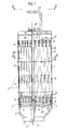
- numeral 1 designates a fuel channel with substantially square cross section.
- the fuel channel surrounds, with no significant play, an upper square portion of a bottom part 2, which has a circular, downwardly-facing inlet opening 3 for cooling water and moderator water.
- the bottom part 2 also supports a supporting plate 4.
- the fuel channel 1 has a relatively thick wall portion which is fixed to the bottom part 2 and the supporting plate 4 by means of a plurality of horizontal bolts, indicated by dash-dotted lines 5.
- the fuel channel 1 is divided into four vertical tubular parts 6 having at least substantially square cross section.
- the support member 7 is welded to the four walls 1a, 1b, 1c and 1d of th fuel channel 1 and has four hollow wings 8.
- the central channel formed by the support member is designated 32 and is connected at its lower part to an inlet tube 9 for moderator water.
- Each tubular part 6 contains a bundle 25 of twenty-five fuel rods 20.
- the rods are arranged in a symmetrical lattice in five rows each containing five rods.
- Each rod is included in two rows perpendicular to each other.
- Each bundle is arranged with a bottom tie plate 11, a top tie plate 12 and a plurality of spacers 13.
- a fuel rod bundle 25 with a bottom tie plate, a top tie plate 12, spacers 13 and a casing part 6 forms a unit which in this application is referred to as a fuel assembly, whereas the device comprising four such fuel assemblies shown in Figures 1-3 is referred to as a composed fuel assembly.
- the composed fuel assembly the four bottom tie plates 11 are supported by the supporting plate 4 and are partially each inserted into a corresponding square hole 14 therein.
- at least one of the fuel rods is provided with relatively long, threaded end plugs 33 and 34 of solid cladding material, the lower end plug 33 being passed through the bottom tie plate 11 and provided with a nut 15 and the upper end plug 34 being passed through the top tie plate 12 and provided with a nut 16.
- the centre rod 26 is formed in this way.
- This rod also serves as spacer holder rod.
- An upper end portion of the fuel channel 1 surrounds a cruciform lifting plate 17 with four horizontal arms 18, 19, 20 and 21, which extend from a common central portion. At the outer end each arms has an arrowhead-like portion 22, which in each respective corner of the fuel channel 1 makes contact with the inner wall surface of the fuel channel 1.
- a lifting handle 23 is fixed to the arms 20 and 21.
- the lifting plate 17 and the handle 23 together form a steel lifting member cast in one piece.
- the lifting plate 17 is fixed to the support member 7 by inserting four vertical bars 28 into respective wings 8 of the support member 7 and welding them thereto.
- each bar 28 has a vertical, bolt-like portion 29 which is passed with play through a corresponding hole in the mid-portion of the lifting plate 17 and provided with a nut 30.
- the fuel channel 1 is provided with indentations 31, intermittently arranged in the longitudinal direction, to which the wings 8 of the support member 7 are welded.
- FIG 4 which shows three adjacently positioned fuel assemblies for a pressurized water reactor
- the vertical fuel rods are designated 42
- the rectangular top tie plates 43 the rectangular bottom tie plates 44
- the spacer members by means of which the fuel rods are positioned, are designated 45.
- Guide tube members 46 for control rod pins are fixed at their upper ends to the top tie plates 43 and at their lower ends to the bottom tie plates 44. In addition, they are fixed to the spacer members 45.
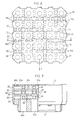
- the bottom tie plate according to Figures 6 and 7 have through-holes 50 for conducting water through the bottom tie plate.
- the holes have parts 50a and 50b, the centre lines of which are displaced in relation to each other.
- the part 50a of a through-hole on the inlet side 51 of the plate for the water is common to several parts 50b of through-holes on the outlet side 52 of the plate.
- the part 50a of a through-hole on the inlet side 51 of the bottom tie plate has a larger cross section than one part 50b of a through-hole on the outlet side 52 of the bottom tie plate.
- Parts 50a of through-holes are in the exemplified case - but need not be so - arranged in open communication with one or more edge sides 53 by way of transverse channels 54 which at the edge have orifices 55 which are arranged in open communication with the spaces between the fuel rods in the same fuel assembly for a boiling water reactor or in the same and adjacent fuel assemblies in a pressurized water reactor.
- the open communication is achieved by means of recesses 56 on the edge side 53 of the bottom tie plate.
- the surface 57 makes contact with the supporting plate 4 and the edge side 53 makes contact with the casing of the fuel channel 1, which means that the water which has passed through the orifices 55 flows up to the space between the fuel rods 10.
- the water which passes through the holes 50a and 50b also flows up to the space between the fuel rods.
- the holes, 50a and 50b are drawn schematically as holes of a conventional kind.
- the holes for the end plugs of the fuel rods in the bottom tie plate are designated 59.
- the bottom tie plate according to Figures 6 and 7 When the bottom tie plate according to Figures 6 and 7 is used in a fuel assembly for a pressurized water reactor, for example the fuel assembly shown in Figure 4, the bottom tie plate has no holes (59) for fuel rods and the edge side 53 makes contact with an edge side in another fuel assembly of the same kind.
- the recesses 56 extend all the way down to the lower edge of the edge side 53 but two adjacent bottom tie plates make contact with each other along their entire horizontal extension along an edge at the bottom of each edge side.
- the water which has passed through the orifices 55 thereby flows via the recesses 56 up to the spaces between the fuel rods 42 above the bottom tie plate and in spaces between adjacent fuel assemblies since there are no partitions between the fuel assemblies.
- Parts 50a of through-holes are also arranged in the illustrated case in open communication with each other via transverse channels 58.
- the embodiment of the bottom tie plate according to Figures 8 and 9 differs from the embodiment according to Figures 6 and 7 in that it has several transverse channels.
- transverse channels 54 which connect parts 50a of through-holes with edge sides 53
- transverse channels 58 which connect parts 50a with each other
- transverse channels 60 which connect parts 50b of through-holes with each other and with edge sides 53.
- the bottom tie plate according to Figures 8 and 9 may be used in the same way as the bottom tie plate according to Figures 6 and 7, i.e. as such in a fuel assembly according to Figure 1 and in modified form without holes (59) for fuel rods and with recesses (56) which are shut off at the bottom in a pressurized water reactor.
- the inlet side for the water is designated 61 and the outlet side, facing the fuel rods, is designated 62.
- the through-holes in the bottom tie plate according to Figure 10 have parts 70a and 70b, the centre lines of which make an angle with each other.
- the throughholes are arranged with a pocket 71 for capturing debris.
- a part which extends from one side for example a part 70a extending from the side 61, is arranged in open communication with two or three parts which extend from the other side of the bottom tie plate, i.e. two or three parts 70b extending from the side 62.
- the bottom tie plate is also provided with pockets 71.
- a bottom tie plate of the kind illustrated in Figure 12 has an exceedingly large open inner volume.
- the bottom tie plates according to Figures 10-12 are used in the illustrated embodiment in a fuel assembly according to Figure 4. When using it in a fuel assembly according to Figure 1, it is provided with holes corresponding to the holes 59 in the bottom tie plates according to Figures 6-9, for end plugs for fuel rods 10. Such holes are not visible in the shown cross section.
- strainer plate 80 It may be suitable to combine the use of the described bottom tie plates with the use of a separate strainer means with a low flow resistance to water to ensure that objects of debris with different shapes are captured and prevented from entering sensitive parts of the fuel assembly.
- the use of such a separate strainer means in the form of a strainer plate 80 is shown in dashed lines in Figure 1.
- the strainer plate may, for example, be fixed to the end plug 33 which is extended with an extra nut 81.
Landscapes
- Physics & Mathematics (AREA)
- Engineering & Computer Science (AREA)
- Plasma & Fusion (AREA)
- General Engineering & Computer Science (AREA)
- High Energy & Nuclear Physics (AREA)
- Monitoring And Testing Of Nuclear Reactors (AREA)
- Structure Of Emergency Protection For Nuclear Reactors (AREA)
- Organic Low-Molecular-Weight Compounds And Preparation Thereof (AREA)
Applications Claiming Priority (2)
| Application Number | Priority Date | Filing Date | Title |
|---|---|---|---|
| SE8904229A SE465192B (sv) | 1989-12-15 | 1989-12-15 | Braenslepatron foer en kaernreaktor av laettvattentyp |
| SE8904229 | 1989-12-15 |
Publications (2)
| Publication Number | Publication Date |
|---|---|
| EP0432739A1 true EP0432739A1 (de) | 1991-06-19 |
| EP0432739B1 EP0432739B1 (de) | 1994-08-10 |
Family
ID=20377781
Family Applications (1)
| Application Number | Title | Priority Date | Filing Date |
|---|---|---|---|
| EP90123850A Expired - Lifetime EP0432739B1 (de) | 1989-12-15 | 1990-12-11 | Kernbrennstoffbündel für einen Leichtwasserreaktor |
Country Status (7)
| Country | Link |
|---|---|
| US (1) | US5100611A (de) |
| EP (1) | EP0432739B1 (de) |
| JP (1) | JP3034055B2 (de) |
| DE (1) | DE69011486T2 (de) |
| ES (1) | ES2063886T3 (de) |
| FI (1) | FI906189A7 (de) |
| SE (1) | SE465192B (de) |
Cited By (12)
| Publication number | Priority date | Publication date | Assignee | Title |
|---|---|---|---|---|
| US5345483A (en) * | 1993-12-02 | 1994-09-06 | General Electric Company | Lower tie plate strainers having double plate with offset holes for boiling water reactors |
| EP0620558A1 (de) * | 1993-04-12 | 1994-10-19 | General Electric Company | Trümmerrückhaltevorrichtung für Siedewasserreaktor |
| US5390221A (en) * | 1993-08-23 | 1995-02-14 | General Electric Company | Debris filters with flow bypass for boiling water reactors |
| US5390220A (en) * | 1993-11-29 | 1995-02-14 | General Electric Company | Lower tie plate strainers including helical spring strainers for boiling water reactors |
| US5473650A (en) * | 1994-04-15 | 1995-12-05 | General Electric Company | Lower tie plate debris catcher for a nuclear reactor |
| US5483564A (en) * | 1993-04-12 | 1996-01-09 | General Electric Company | Lower tie plate strainers including double corrugated strainers for boiling water reactors |
| US5488634A (en) * | 1994-02-10 | 1996-01-30 | General Electric Company | Lower tie plate debris catcher for a nuclear reactor |
| US5519745A (en) * | 1994-11-03 | 1996-05-21 | General Electric Company | Lower tie plate debris catcher for a nuclear reactor |
| US5528640A (en) * | 1994-11-07 | 1996-06-18 | General Electric Company | Low pressure double offset plate catcher for a nuclear reactor |
| US5539793A (en) * | 1994-10-27 | 1996-07-23 | General Electric Company | Lower tie plate debris catcher for a nuclear reactor |
| US5748694A (en) * | 1996-03-26 | 1998-05-05 | General Electric Company | Fuel bundle filter for a nuclear reactor fuel bundle assembly |
| WO2002075746A1 (en) * | 2001-03-20 | 2002-09-26 | Westinghouse Atom Ab | Filter and fuel assembly for a light-water nuclear reactor |
Families Citing this family (13)
| Publication number | Priority date | Publication date | Assignee | Title |
|---|---|---|---|---|
| US5219517A (en) * | 1989-12-14 | 1993-06-15 | Abb Atom Ab | Fuel assembly for a boiling water nuclear reactor |
| SE9202828L (sv) * | 1992-09-30 | 1994-03-31 | Asea Atom Ab | Bränsleelement för en kärnreaktor av lättvattentyp |
| SE509238C2 (sv) * | 1993-07-05 | 1998-12-21 | Asea Atom Ab | Reaktorhärd |
| US5406604A (en) * | 1993-11-18 | 1995-04-11 | General Electric Company | Two part tie plate adapted to D & C lattice |
| US5481578A (en) * | 1994-06-24 | 1996-01-02 | General Electric Company | Perforated tube debris catcher for a nuclear reactor |
| SE521610C2 (sv) | 2001-01-22 | 2003-11-18 | Westinghouse Atom Ab | Filter och bränslepatron för en nukleär anläggning av lättvattentyp |
| TW557450B (en) * | 2001-07-16 | 2003-10-11 | Toshiba Corp | Fuel supporting attachment, fuel inlet mechanism, and fuel assembly |
| US7822165B2 (en) * | 2004-01-05 | 2010-10-26 | Westinghouse Electric Co Llc | Nuclear fuel assembly debris filter bottom nozzle |
| US20070084782A1 (en) * | 2005-10-05 | 2007-04-19 | Enercon Services, Inc. | Filter medium for strainers used in nuclear reactor emergency core cooling systems |
| US8396182B2 (en) * | 2007-08-31 | 2013-03-12 | Global Nuclear Fuel—Americas, LLC | Method and apparatus to shield a nuclear fuel assembly with removable debris shield in upper tie |
| US20090060114A1 (en) * | 2007-08-31 | 2009-03-05 | Global Nuclear Fuel - Americas, Llc | Debris shield for upper tie plate in a nuclear fuel bundle and method for filtering debris |
| US20110164719A1 (en) * | 2010-01-05 | 2011-07-07 | Westinghouse Electric Company, Llc | Nuclear fuel assembly debris filter bottom nozzle |
| US10923237B2 (en) * | 2017-08-28 | 2021-02-16 | Global Nuclear Fuel—Americas, LLC | Debris filters for nuclear fuel assembly and method of using the same |
Family Cites Families (3)
| Publication number | Priority date | Publication date | Assignee | Title |
|---|---|---|---|---|
| US4053359A (en) * | 1974-09-04 | 1977-10-11 | The United States Of America As Represented By The United States Energy Research And Development Administration | Nuclear reactor |
| SE424237B (sv) * | 1980-10-29 | 1982-07-05 | Asea Atom Ab | Brensleelement for en kokarreaktor |
| SE450177B (sv) * | 1985-10-16 | 1987-06-09 | Asea Atom Ab | Kernbrenslepatron |
-
1989
- 1989-12-15 SE SE8904229A patent/SE465192B/sv unknown
-
1990
- 1990-12-10 US US07/625,137 patent/US5100611A/en not_active Expired - Lifetime
- 1990-12-11 ES ES90123850T patent/ES2063886T3/es not_active Expired - Lifetime
- 1990-12-11 EP EP90123850A patent/EP0432739B1/de not_active Expired - Lifetime
- 1990-12-11 DE DE69011486T patent/DE69011486T2/de not_active Expired - Lifetime
- 1990-12-14 FI FI906189A patent/FI906189A7/fi not_active IP Right Cessation
- 1990-12-14 JP JP2402500A patent/JP3034055B2/ja not_active Expired - Lifetime
Cited By (15)
| Publication number | Priority date | Publication date | Assignee | Title |
|---|---|---|---|---|
| EP0620558A1 (de) * | 1993-04-12 | 1994-10-19 | General Electric Company | Trümmerrückhaltevorrichtung für Siedewasserreaktor |
| US5384814A (en) * | 1993-04-12 | 1995-01-24 | General Electric Company | Lower tie plate strainers for boiling water reactors |
| US5483564A (en) * | 1993-04-12 | 1996-01-09 | General Electric Company | Lower tie plate strainers including double corrugated strainers for boiling water reactors |
| US5390221A (en) * | 1993-08-23 | 1995-02-14 | General Electric Company | Debris filters with flow bypass for boiling water reactors |
| US5390220A (en) * | 1993-11-29 | 1995-02-14 | General Electric Company | Lower tie plate strainers including helical spring strainers for boiling water reactors |
| EP0656630A1 (de) * | 1993-12-02 | 1995-06-07 | General Electric Company | Sieb mit versetzten Öffnungen versehener Doppelplatte für untere Halteplatte in Siedewasserreaktoren |
| US5345483A (en) * | 1993-12-02 | 1994-09-06 | General Electric Company | Lower tie plate strainers having double plate with offset holes for boiling water reactors |
| US5488634A (en) * | 1994-02-10 | 1996-01-30 | General Electric Company | Lower tie plate debris catcher for a nuclear reactor |
| US5473650A (en) * | 1994-04-15 | 1995-12-05 | General Electric Company | Lower tie plate debris catcher for a nuclear reactor |
| US5539793A (en) * | 1994-10-27 | 1996-07-23 | General Electric Company | Lower tie plate debris catcher for a nuclear reactor |
| US5519745A (en) * | 1994-11-03 | 1996-05-21 | General Electric Company | Lower tie plate debris catcher for a nuclear reactor |
| US5528640A (en) * | 1994-11-07 | 1996-06-18 | General Electric Company | Low pressure double offset plate catcher for a nuclear reactor |
| US5748694A (en) * | 1996-03-26 | 1998-05-05 | General Electric Company | Fuel bundle filter for a nuclear reactor fuel bundle assembly |
| WO2002075746A1 (en) * | 2001-03-20 | 2002-09-26 | Westinghouse Atom Ab | Filter and fuel assembly for a light-water nuclear reactor |
| US6876713B2 (en) | 2001-03-20 | 2005-04-05 | Westinghouse Atom Ab | Filter and fuel assembly for a light-water nuclear reactor |
Also Published As
| Publication number | Publication date |
|---|---|
| FI906189A0 (fi) | 1990-12-14 |
| ES2063886T3 (es) | 1995-01-16 |
| FI906189L (fi) | 1991-06-16 |
| SE8904229L (sv) | 1991-06-16 |
| JP3034055B2 (ja) | 2000-04-17 |
| US5100611A (en) | 1992-03-31 |
| SE465192B (sv) | 1991-08-05 |
| DE69011486T2 (de) | 1995-03-30 |
| EP0432739B1 (de) | 1994-08-10 |
| FI906189A7 (fi) | 1991-06-16 |
| SE8904229D0 (sv) | 1989-12-15 |
| JPH03259794A (ja) | 1991-11-19 |
| DE69011486D1 (de) | 1994-09-15 |
Similar Documents
| Publication | Publication Date | Title |
|---|---|---|
| EP0432739B1 (de) | Kernbrennstoffbündel für einen Leichtwasserreaktor | |
| US5219517A (en) | Fuel assembly for a boiling water nuclear reactor | |
| EP0432738B1 (de) | Brennstoffeinheit für einen Siedewasserreaktor | |
| EP0474353B1 (de) | Fussstückplatte für Brennstabbündel eines Kernreaktors | |
| US5024806A (en) | Enhanced debris filter bottom nozzle for a nuclear fuel assembly | |
| US4795608A (en) | Nuclear fuel assembly | |
| EP0311037B1 (de) | Gegen Teilchen widerstandsfähiges Fussstück eines Kernbrennelements | |
| US5230861A (en) | Fuel assembly for a light-water nuclear reactor | |
| JP3065119B2 (ja) | 燃料集合体の破片フィルタ | |
| EP0589312A1 (de) | Guss-Fussstück für Kernbrennstabbündel | |
| JPH0439918B2 (de) | ||
| EP0219038B1 (de) | Kernbrennstabbündel | |
| CS211991A3 (en) | Bottom platform of fuel system for nuclear reactor | |
| JP2022533428A (ja) | 核燃料集合体底部ノズル用のデブリ濾過装置及びそれを含む底部ノズル | |
| KR20190121858A (ko) | 핵연료 집합체 잔해물 여과 하부 노즐 | |
| EP0590617B1 (de) | Spaltzone für Siedewasserkernreaktor | |
| JPH08254589A (ja) | 燃料バンドル・アセンブリ | |
| EP0206163A2 (de) | Kernbrennstabbündel | |
| US20130272479A1 (en) | Lower end fitting for nuclear fuel assembly made from intersecting metal strips | |
| EP0570905B1 (de) | Brennstabbündel mit Trümmelfänger für Leichtwasserkernreaktor | |
| JP5710836B2 (ja) | 核燃料集合体のタイプレート、該タイプレートを備えた上部ノズル及び核燃料集合体 | |
| US4738819A (en) | Boiling water nuclear reactor fuel assembly with cross-flow elimination at upper spacer locations | |
| JPH11505926A (ja) | 沸騰水型原子炉の燃料集合体 | |
| US5896436A (en) | Fuel assembly for a boiling water reactor | |
| BR112021023297B1 (pt) | Arranjo de filtragem, e, conjunto de bocais de fundo |
Legal Events
| Date | Code | Title | Description |
|---|---|---|---|
| PUAI | Public reference made under article 153(3) epc to a published international application that has entered the european phase |
Free format text: ORIGINAL CODE: 0009012 |
|
| AK | Designated contracting states |
Kind code of ref document: A1 Designated state(s): CH DE ES LI |
|
| 17P | Request for examination filed |
Effective date: 19911212 |
|
| 17Q | First examination report despatched |
Effective date: 19931005 |
|
| GRAA | (expected) grant |
Free format text: ORIGINAL CODE: 0009210 |
|
| AK | Designated contracting states |
Kind code of ref document: B1 Designated state(s): CH DE ES LI |
|
| REF | Corresponds to: |
Ref document number: 69011486 Country of ref document: DE Date of ref document: 19940915 |
|
| REG | Reference to a national code |
Ref country code: ES Ref legal event code: FG2A Ref document number: 2063886 Country of ref document: ES Kind code of ref document: T3 |
|
| PLBE | No opposition filed within time limit |
Free format text: ORIGINAL CODE: 0009261 |
|
| STAA | Information on the status of an ep patent application or granted ep patent |
Free format text: STATUS: NO OPPOSITION FILED WITHIN TIME LIMIT |
|
| 26N | No opposition filed | ||
| PGFP | Annual fee paid to national office [announced via postgrant information from national office to epo] |
Ref country code: CH Payment date: 19991210 Year of fee payment: 10 |
|
| PG25 | Lapsed in a contracting state [announced via postgrant information from national office to epo] |
Ref country code: CH Free format text: LAPSE BECAUSE OF NON-PAYMENT OF DUE FEES Effective date: 20001231 Ref country code: LI Free format text: LAPSE BECAUSE OF NON-PAYMENT OF DUE FEES Effective date: 20001231 |
|
| REG | Reference to a national code |
Ref country code: CH Ref legal event code: PL |
|
| PGFP | Annual fee paid to national office [announced via postgrant information from national office to epo] |
Ref country code: ES Payment date: 20091217 Year of fee payment: 20 |
|
| PGFP | Annual fee paid to national office [announced via postgrant information from national office to epo] |
Ref country code: DE Payment date: 20091224 Year of fee payment: 20 |
|
| REG | Reference to a national code |
Ref country code: ES Ref legal event code: FD2A Effective date: 20110223 |
|
| PG25 | Lapsed in a contracting state [announced via postgrant information from national office to epo] |
Ref country code: ES Free format text: LAPSE BECAUSE OF EXPIRATION OF PROTECTION Effective date: 20101212 |
|
| PG25 | Lapsed in a contracting state [announced via postgrant information from national office to epo] |
Ref country code: DE Free format text: LAPSE BECAUSE OF EXPIRATION OF PROTECTION Effective date: 20101211 |