EP0432852A1 - Dispositif de démarrage pour un moteur synchrone monophasé bipolaire avec rotor à aimant permanent - Google Patents
Dispositif de démarrage pour un moteur synchrone monophasé bipolaire avec rotor à aimant permanent Download PDFInfo
- Publication number
- EP0432852A1 EP0432852A1 EP90203243A EP90203243A EP0432852A1 EP 0432852 A1 EP0432852 A1 EP 0432852A1 EP 90203243 A EP90203243 A EP 90203243A EP 90203243 A EP90203243 A EP 90203243A EP 0432852 A1 EP0432852 A1 EP 0432852A1
- Authority
- EP
- European Patent Office
- Prior art keywords
- rotor
- load
- play
- angle
- positive
- Prior art date
- Legal status (The legal status is an assumption and is not a legal conclusion. Google has not performed a legal analysis and makes no representation as to the accuracy of the status listed.)
- Granted
Links
- 230000001360 synchronised effect Effects 0.000 title claims abstract description 18
- 239000000853 adhesive Substances 0.000 claims abstract description 42
- 230000001070 adhesive effect Effects 0.000 claims abstract description 42
- 230000000903 blocking effect Effects 0.000 claims abstract description 38
- 230000005415 magnetization Effects 0.000 claims abstract description 22
- 230000009467 reduction Effects 0.000 claims description 20
- 230000008878 coupling Effects 0.000 description 11
- 238000010168 coupling process Methods 0.000 description 11
- 238000005859 coupling reaction Methods 0.000 description 11
- 230000001419 dependent effect Effects 0.000 description 7
- XEEYBQQBJWHFJM-UHFFFAOYSA-N Iron Chemical compound [Fe] XEEYBQQBJWHFJM-UHFFFAOYSA-N 0.000 description 4
- 230000005540 biological transmission Effects 0.000 description 4
- 230000008901 benefit Effects 0.000 description 3
- 230000000694 effects Effects 0.000 description 2
- 230000003993 interaction Effects 0.000 description 2
- 229910052742 iron Inorganic materials 0.000 description 2
- 238000000034 method Methods 0.000 description 2
- 230000008569 process Effects 0.000 description 2
- 230000008859 change Effects 0.000 description 1
- 238000010276 construction Methods 0.000 description 1
- 230000002349 favourable effect Effects 0.000 description 1
- 230000004907 flux Effects 0.000 description 1
- 230000012447 hatching Effects 0.000 description 1
- 238000002347 injection Methods 0.000 description 1
- 239000007924 injection Substances 0.000 description 1
- 238000009434 installation Methods 0.000 description 1
- 230000001788 irregular Effects 0.000 description 1
- 239000007788 liquid Substances 0.000 description 1
- 230000007246 mechanism Effects 0.000 description 1
- 230000004048 modification Effects 0.000 description 1
- 238000012986 modification Methods 0.000 description 1
- 238000007493 shaping process Methods 0.000 description 1
- 238000005406 washing Methods 0.000 description 1
Images



Classifications
-
- H—ELECTRICITY
- H02—GENERATION; CONVERSION OR DISTRIBUTION OF ELECTRIC POWER
- H02K—DYNAMO-ELECTRIC MACHINES
- H02K7/00—Arrangements for handling mechanical energy structurally associated with dynamo-electric machines, e.g. structural association with mechanical driving motors or auxiliary dynamo-electric machines
- H02K7/10—Structural association with clutches, brakes, gears, pulleys or mechanical starters
- H02K7/118—Structural association with clutches, brakes, gears, pulleys or mechanical starters with starting devices
- H02K7/1185—Structural association with clutches, brakes, gears, pulleys or mechanical starters with starting devices with a mechanical one-way direction control, i.e. with means for reversing the direction of rotation of the rotor
Definitions
- the invention relates to a starting aid for a two-pole single-phase synchronous motor with a permanent-magnet rotor and a magnetic adhesive torque, which has positive and negative values seen over one revolution with the resulting stable and unstable rest positions, the stable rest positions being offset by the asymmetry angle y in the positive direction are offset from the middle field direction of the stator field and a critical adhesive moment M klkr is effective in the parallel position of the stator field and rotor field, consisting of a torsional backlash between a driving part connected to the rotor and a load part and a direction lock, the backlash angle E of the backlash between the load side and motor-side components, around which the components can rotate uncoupled against each other, are limited in the positive and negative direction of rotation by means of positive and negative game walls of the rotor or load-side components.
- the negative load and rotor play walls are those that are in operation in the negative direction of rotation of the rotor, the positive load and rotor play walls are present when the rotor has passed through the game in the positive direction.
- This definition also applies to the arrangements described below with gears, in which the play means are attached to the second gear stage, the direction of rotation of which is reversed from that of the rotor.
- the naming of the game walls always refers to the direction of rotation of the rotor.
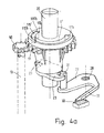
- Two locking lugs 23 are provided on the rotor shaft 13.
- the locking lugs 23 act together with a locking member 27 which is rotatable about a mounting 28 fixed to the chassis.
- the locking member 27 has a spring arm 29, which is supported on a chassis-fixed abutment 30.
- the locking member 27 carries a locking pin 31 which is designed to cooperate with the locking lugs 23.
- the spring arm 29 presses the locking member and with it the locking pin 31 constantly in the direction of the rotor shaft 13.
- the locking member 27, the locking pin 31, the spring arm 29 and the abutment 30 consist of a plastic injection molded part.
- the play angle E denotes the angle by which the driver part 33 can move freely with respect to the load part 19 without taking the locking member 27 into account.
- the play angle e is determined by the free distance between the load play walls 35/36 of the coupling grooves 17 minus the width of the drive cam 15 the rotor play walls 38/49.
- the blocking angle K is also entered; it designates the angle between the stator field direction 39 and the magnetization direction 41, at which the rotor is blocked in the case of a positive direction of rotation before the two fields are parallel.
- FIG. 3 shows a second embodiment, in which the direction lock 22 is arranged on a gear between the rotor shaft 13 and the load shaft 20.
- 3 shows the single-phase synchronous motor 1 in an embodiment corresponding to that of FIG. 1.
- a pinion 50 is arranged on the rotor shaft 13, which meshes with a gear toothed wheel 51 and thus forms a gear 47.
- a cylindrical free space is provided in the gear wheel 51, into which drive cams 37g engage inwards.
- arcuate movement paths 17g form between the cams 37g, which are delimited by rotor play walls, namely a positive rotor play wall 38g and a negative rotor play wall 49g.
- the drive pinion 50 which meshes with the gear toothed wheel 51, which can rotate with the rotor 11 via the rotor shaft 13, can be driven to the drive pinion 50 has an integer reduction ratio.
- the play angle e between the gear wheel 51 and the load shaft 20 allows the rotor a free rotation that is greater than the blocking angle K, preferably greater than 90 ° minus the asymmetry angle y.
Landscapes
- Engineering & Computer Science (AREA)
- Power Engineering (AREA)
- Connection Of Motors, Electrical Generators, Mechanical Devices, And The Like (AREA)
- Synchronous Machinery (AREA)
- Permanent Magnet Type Synchronous Machine (AREA)
Applications Claiming Priority (2)
| Application Number | Priority Date | Filing Date | Title |
|---|---|---|---|
| DE3941204A DE3941204A1 (de) | 1989-12-14 | 1989-12-14 | Anlaufhilfe fuer einen zweipoligen einphasensynchronmotor mit dauermagnetischem rotor |
| DE3941204 | 1989-12-14 |
Publications (2)
| Publication Number | Publication Date |
|---|---|
| EP0432852A1 true EP0432852A1 (fr) | 1991-06-19 |
| EP0432852B1 EP0432852B1 (fr) | 1994-05-25 |
Family
ID=6395405
Family Applications (1)
| Application Number | Title | Priority Date | Filing Date |
|---|---|---|---|
| EP90203243A Expired - Lifetime EP0432852B1 (fr) | 1989-12-14 | 1990-12-10 | Dispositif de démarrage pour un moteur synchrone monophasé bipolaire avec rotor à aimant permanent |
Country Status (4)
| Country | Link |
|---|---|
| US (1) | US5118977A (fr) |
| EP (1) | EP0432852B1 (fr) |
| JP (1) | JP2807350B2 (fr) |
| DE (2) | DE3941204A1 (fr) |
Cited By (1)
| Publication number | Priority date | Publication date | Assignee | Title |
|---|---|---|---|---|
| WO2007052210A1 (fr) * | 2005-10-31 | 2007-05-10 | Arcelik Anonim Sirketi | Moteur |
Families Citing this family (9)
| Publication number | Priority date | Publication date | Assignee | Title |
|---|---|---|---|---|
| US6227822B1 (en) | 1998-10-20 | 2001-05-08 | Lakewood Engineering And Manufacturing Co. | Fan with improved electric motor and mounting |
| DE10004059A1 (de) * | 2000-02-01 | 2001-11-08 | Buhler Motor Gmbh | Mehrphasen-Motor |
| US6356000B1 (en) * | 2001-02-02 | 2002-03-12 | Chun-Yuan Ho | Magnetically augmented rotation system |
| US6975049B2 (en) * | 2003-10-29 | 2005-12-13 | A. O. Smith Corporation | Electrical machine and method of manufacturing the same |
| CN102824947B (zh) * | 2012-07-20 | 2014-10-15 | 东莞市邦泽电子有限公司 | 一种使用永磁同步电机的碎纸机 |
| CN103501095B (zh) * | 2013-10-07 | 2015-09-02 | 江门市地尔汉宇电器股份有限公司 | 一种使用“u”字形铁芯的微型永磁同步电动机和排水泵 |
| CN105322730B (zh) * | 2014-07-28 | 2017-09-15 | 江门市地尔汉宇电器股份有限公司 | 一种永磁同步电机及其制备方法 |
| KR102501807B1 (ko) * | 2021-07-13 | 2023-02-17 | 연세대학교 산학협력단 | 단일 액추에이터 기반 다자유도 자기부상 시스템 |
| US20230275490A1 (en) * | 2022-02-28 | 2023-08-31 | Illinois Tool Works Inc. | Dishwasher diverter valve drive |
Citations (4)
| Publication number | Priority date | Publication date | Assignee | Title |
|---|---|---|---|---|
| FR2184170A5 (fr) * | 1972-05-09 | 1973-12-21 | Crouzet Sa | |
| GB1413782A (en) * | 1974-05-17 | 1975-11-12 | Mallory Timers Ltd | Synchronous motor including means preventing continued rotation in a wrongway direction of the rotor |
| DE3420371A1 (de) * | 1984-01-02 | 1985-07-11 | Robert Bosch Gmbh, 7000 Stuttgart | Anordnung zum starten eines synchronmotors |
| DE8703451U1 (de) * | 1987-03-07 | 1988-07-07 | Robert Bosch Gmbh, 7000 Stuttgart | Selbstanlaufender Synchronmotor mit Rücklaufsperre |
Family Cites Families (5)
| Publication number | Priority date | Publication date | Assignee | Title |
|---|---|---|---|---|
| US4241270A (en) * | 1977-12-27 | 1980-12-23 | Tri-Tech, Inc. | Synchronous electric motor |
| US4528533A (en) * | 1982-07-28 | 1985-07-09 | General Scanning, Inc. | Actuator with compensating flux path |
| DE3301263C2 (de) * | 1983-01-17 | 1986-07-31 | Philips Patentverwaltung Gmbh, 2000 Hamburg | Einphasensynchronmotor mit einem zweipoligen dauermagnetischen Läufer |
| US4728832A (en) | 1986-08-07 | 1988-03-01 | Honeywell Inc. | Alternating current motor with directional rotation reliability |
| JP2604143B2 (ja) * | 1987-01-14 | 1997-04-30 | 三洋電機株式会社 | 小型ブラシレスモータ |
-
1989
- 1989-12-14 DE DE3941204A patent/DE3941204A1/de not_active Withdrawn
-
1990
- 1990-12-10 EP EP90203243A patent/EP0432852B1/fr not_active Expired - Lifetime
- 1990-12-10 DE DE59005817T patent/DE59005817D1/de not_active Expired - Fee Related
- 1990-12-12 JP JP2409847A patent/JP2807350B2/ja not_active Expired - Lifetime
- 1990-12-14 US US07/628,262 patent/US5118977A/en not_active Expired - Fee Related
Patent Citations (4)
| Publication number | Priority date | Publication date | Assignee | Title |
|---|---|---|---|---|
| FR2184170A5 (fr) * | 1972-05-09 | 1973-12-21 | Crouzet Sa | |
| GB1413782A (en) * | 1974-05-17 | 1975-11-12 | Mallory Timers Ltd | Synchronous motor including means preventing continued rotation in a wrongway direction of the rotor |
| DE3420371A1 (de) * | 1984-01-02 | 1985-07-11 | Robert Bosch Gmbh, 7000 Stuttgart | Anordnung zum starten eines synchronmotors |
| DE8703451U1 (de) * | 1987-03-07 | 1988-07-07 | Robert Bosch Gmbh, 7000 Stuttgart | Selbstanlaufender Synchronmotor mit Rücklaufsperre |
Cited By (2)
| Publication number | Priority date | Publication date | Assignee | Title |
|---|---|---|---|---|
| WO2007052210A1 (fr) * | 2005-10-31 | 2007-05-10 | Arcelik Anonim Sirketi | Moteur |
| CN101300724B (zh) * | 2005-10-31 | 2012-07-04 | 阿塞里克股份有限公司 | 电动机 |
Also Published As
| Publication number | Publication date |
|---|---|
| EP0432852B1 (fr) | 1994-05-25 |
| JP2807350B2 (ja) | 1998-10-08 |
| DE3941204A1 (de) | 1991-06-20 |
| DE59005817D1 (de) | 1994-06-30 |
| JPH04105540A (ja) | 1992-04-07 |
| US5118977A (en) | 1992-06-02 |
Similar Documents
| Publication | Publication Date | Title |
|---|---|---|
| DE3751215T2 (de) | Magnetisch rotierende anordnung. | |
| DE69210331T2 (de) | Einen verdrehten Pol aufweisender Einphasenmotor mit veränderlicher Reluktanz | |
| DE2600840C3 (de) | Schrittmotor mit einem Permanentmagnet-Rotor | |
| DE10333092A1 (de) | Drehbetätigungsvorrichtung | |
| DE102004054397B4 (de) | Elektromagnetisches Stellglied | |
| EP0432852B1 (fr) | Dispositif de démarrage pour un moteur synchrone monophasé bipolaire avec rotor à aimant permanent | |
| DE112005003694T5 (de) | Magnetmotor | |
| EP0614263B1 (fr) | Moteur monophasé à réluctance capable de démarrer dans un sens de rotation désiré | |
| EP0103930B1 (fr) | Dispositif de renversement pour un moteur monophasé synchrone â deux pôles | |
| DE2331181B2 (de) | Antriebsvorrichtung für die Betätigungsstange eines Absperrschiebers od. dgl | |
| DE202018103172U1 (de) | Motoranordnung | |
| DE3915539A1 (de) | Elektronisch kommutierter gleichstrommotor | |
| DE8911863U1 (de) | Anlaufhilfe für einen zweipoligen Einphasensynchronmotor mit dauermagnetischem Rotor | |
| DE2642432C2 (de) | Selbstanlaufender Synchronmotor | |
| DE3049191A1 (de) | Elektrischer schrittmotor und ihn verwendende kombination motor-untersetzungsgetriebe | |
| AT523723A4 (de) | Getriebemotor | |
| DE4125692C1 (en) | Alternating drive system e.g. for two pumps - has two coaxial drive shafts driven by electromotor alternatingly with auxiliary coupling allowing simultaneous drive via by=pass gearing | |
| DE69632662T2 (de) | Vorrichtung und Verfahren zum Anlauf eines einphasigen Reluktanzmotors | |
| DE1763855A1 (de) | Synchronmotor mit eindeutig vorgebbarer Drehrichtung | |
| DE2226333A1 (de) | Selbsterregender synchronmotor | |
| DE102024125666B3 (de) | Traktionsmaschine und Fahrzeug | |
| EP0463590B1 (fr) | Dispositif d'entraînement pour réglage de deux positions à auto-maintien | |
| DE4234388A1 (de) | Fahrradlichtmaschine | |
| DE1763078C3 (de) | Schrittmotor | |
| AT374724B (de) | Stanzmaschine zur herstellung von lochreihen in lochkarten fuer die steuerung von textilmaschinen- aggregaten |
Legal Events
| Date | Code | Title | Description |
|---|---|---|---|
| PUAI | Public reference made under article 153(3) epc to a published international application that has entered the european phase |
Free format text: ORIGINAL CODE: 0009012 |
|
| AK | Designated contracting states |
Kind code of ref document: A1 Designated state(s): DE FR GB IT |
|
| 17P | Request for examination filed |
Effective date: 19920123 |
|
| 17Q | First examination report despatched |
Effective date: 19930809 |
|
| GRAA | (expected) grant |
Free format text: ORIGINAL CODE: 0009210 |
|
| AK | Designated contracting states |
Kind code of ref document: B1 Designated state(s): DE FR GB IT |
|
| REF | Corresponds to: |
Ref document number: 59005817 Country of ref document: DE Date of ref document: 19940630 |
|
| ITF | It: translation for a ep patent filed | ||
| GBT | Gb: translation of ep patent filed (gb section 77(6)(a)/1977) |
Effective date: 19940801 |
|
| ET | Fr: translation filed | ||
| PLBE | No opposition filed within time limit |
Free format text: ORIGINAL CODE: 0009261 |
|
| STAA | Information on the status of an ep patent application or granted ep patent |
Free format text: STATUS: NO OPPOSITION FILED WITHIN TIME LIMIT |
|
| ITPR | It: changes in ownership of a european patent |
Owner name: CAMBIO RAGIONE SOCIALE;PHILIPS ELECTRONICS N.V. |
|
| 26N | No opposition filed | ||
| REG | Reference to a national code |
Ref country code: FR Ref legal event code: CD |
|
| PGFP | Annual fee paid to national office [announced via postgrant information from national office to epo] |
Ref country code: GB Payment date: 19971201 Year of fee payment: 8 |
|
| PGFP | Annual fee paid to national office [announced via postgrant information from national office to epo] |
Ref country code: FR Payment date: 19971223 Year of fee payment: 8 |
|
| PGFP | Annual fee paid to national office [announced via postgrant information from national office to epo] |
Ref country code: DE Payment date: 19980223 Year of fee payment: 8 |
|
| REG | Reference to a national code |
Ref country code: FR Ref legal event code: CD |
|
| PG25 | Lapsed in a contracting state [announced via postgrant information from national office to epo] |
Ref country code: GB Free format text: LAPSE BECAUSE OF NON-PAYMENT OF DUE FEES Effective date: 19981210 |
|
| GBPC | Gb: european patent ceased through non-payment of renewal fee |
Effective date: 19981210 |
|
| PG25 | Lapsed in a contracting state [announced via postgrant information from national office to epo] |
Ref country code: FR Free format text: LAPSE BECAUSE OF NON-PAYMENT OF DUE FEES Effective date: 19990831 |
|
| REG | Reference to a national code |
Ref country code: FR Ref legal event code: ST |
|
| PG25 | Lapsed in a contracting state [announced via postgrant information from national office to epo] |
Ref country code: DE Free format text: LAPSE BECAUSE OF NON-PAYMENT OF DUE FEES Effective date: 19991001 |
|
| PG25 | Lapsed in a contracting state [announced via postgrant information from national office to epo] |
Ref country code: IT Free format text: LAPSE BECAUSE OF NON-PAYMENT OF DUE FEES;WARNING: LAPSES OF ITALIAN PATENTS WITH EFFECTIVE DATE BEFORE 2007 MAY HAVE OCCURRED AT ANY TIME BEFORE 2007. THE CORRECT EFFECTIVE DATE MAY BE DIFFERENT FROM THE ONE RECORDED. Effective date: 20051210 |