EP0432854B1 - Dispositif pour la couplage de béton à distance - Google Patents
Dispositif pour la couplage de béton à distance Download PDFInfo
- Publication number
- EP0432854B1 EP0432854B1 EP90203261A EP90203261A EP0432854B1 EP 0432854 B1 EP0432854 B1 EP 0432854B1 EP 90203261 A EP90203261 A EP 90203261A EP 90203261 A EP90203261 A EP 90203261A EP 0432854 B1 EP0432854 B1 EP 0432854B1
- Authority
- EP
- European Patent Office
- Prior art keywords
- jib
- concrete
- parts
- conduit
- finishing
- Prior art date
- Legal status (The legal status is an assumption and is not a legal conclusion. Google has not performed a legal analysis and makes no representation as to the accuracy of the status listed.)
- Expired - Lifetime
Links
Images


Classifications
-
- E—FIXED CONSTRUCTIONS
- E04—BUILDING
- E04G—SCAFFOLDING; FORMS; SHUTTERING; BUILDING IMPLEMENTS OR AIDS, OR THEIR USE; HANDLING BUILDING MATERIALS ON THE SITE; REPAIRING, BREAKING-UP OR OTHER WORK ON EXISTING BUILDINGS
- E04G21/00—Preparing, conveying, or working-up building materials or building elements in situ; Other devices or measures for constructional work
- E04G21/02—Conveying or working-up concrete or similar masses able to be heaped or cast
- E04G21/04—Devices for both conveying and distributing
- E04G21/0418—Devices for both conveying and distributing with distribution hose
- E04G21/0436—Devices for both conveying and distributing with distribution hose on a mobile support, e.g. truck
Definitions
- the invention relates to a device as defined in the introductory part of claim 1.
- a device is known from US-A-3 942 554.
- the concrete conduit is constructed and arranged such that it takes up much space in a device with a reasonable extension distance.
- the invention has for its object to improve a device of the kind said forth above, such that the concrete conduit permits large extension distances of the jib, without taking up much space.
- the jib with the concrete conduit mounted thereon can be fully retracted without parts having to be disassembled.
- the device according to this embodiment is therefore ready for use very rapidly and can be very quickly removed again after completion of work.
- a very favourable further development is characterized in claim 2.
- the finishing head at the end of the jib can be displaced uniformly in a straight line by extending or retracting the jib.
- the poured concrete can thus be directly finished using the finishing head without further manual operations.
- the finishing beam is preferably a vibrating beam so that the surface of the poured and smoothed concrete obtains a high quality.
- concrete can also be poured and finished with the device according to the invention in places difficult of access such as along walls, around columns and the like.
- the finishing head can, for instance by being rotated into a suitable position, also operate when the jib is turned about its vertical rotational axis.
- finishing head is connected height-adjustably to the jib by height adjusting means as characterized in claim 6. Any dipping movements of the jib that may for instance occur when the concrete is supplied using a pulsating concrete pump can be compensated by the height adjusting means so that a precisely flat floor can nevertheless be obtained despite these movements.
- the sensor means are per se known means reacting to a laser reference.
- Fig. 1 shows in perspective view a device according to a preferred embodiment of the invention in the transporting position.
- Fig. 2 is a partly broken away, perspective view of the device of fig. 1 in the position of use with a finishing head attached thereto.
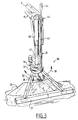
- Fig. 3 is a perspective view of the finishing head.
- the device 1 shown in fig. 1 is embodied as mobile truck, on the frame 2 whereof is mounted a jib 3.
- a bearing construction 4 By means of a bearing construction 4 the whole jib is rotatable about a vertical rotational axis.
- the jib 3 is telescopic and comprises a first part 5, a second jib part 6 slidable in lengthwise direction thereof and a leading or third jib part 7 mounted slidably in lengthwise direction on the front end of the second jib part 6 by means of a guiding construction 12.
- the jib can be further elongated using an extension piece 8 that is connected to the front end of the jib part 7 for sideways swivelling by means of a hinge 9.
- This extension piece 8 can be pivoted forward about the hinge 9 in the direction of arrow 13 in fig. 1, wherein holes 10 come to lie in one line with holes 11 in a support at the forward end of the third jib part 7.
- a locking pin is placed through these holes 10 and 11 lying in one line for fixing the extension piece 8 in the swivelled out position.
- a concrete conduit 15 is arranged along the jib.
- a connection 16 Arranged in the bearing construction 4 for the jib is a connection 16 to which is connected a concrete pump. This connection 16 is joined to the concrete conduit 15 via per se known rotatable couplings.
- a first portion of the concrete conduit 15 extends along a supporting beam 17 extending substantially parallel to the first jib part 5 and mounted thereon by means of a support 19.
- a leading portion of the concrete conduit 15 is mounted directly against the third jib part 7.
- Two coupling pieces 20 Arranged between the end of the concrete conduit portion fitted along supporting beam 17 and the concrete conduit portion fitted along jib part 7 are two coupling pieces 20 which permit a relative movement of the said concrete conduit portions 15 during extending or retracting of the jib parts.
- each coupling piece 20 comprises a first tube portion 21 and a second tube portion 22, each of which are connected via the respective 90° couplings 23 and 24, which are rotatable about an axis transversely of the jib, to a conduit portion connected to a different jib part.
- the tube portion 21 of the coupling piece 20 on the right-hand side of the jib is connected with its end via the 90° coupling 23 to the conduit part arranged along the supporting beam 17.
- Tube portion 22 is connected via the 90° coupling 24 to a transverse conduit part mounted on the end of a supporting beam 18 which protrudes rearward from the head of the second jib part 6.
- a similar coupling piece 20 which leads to the concrete conduit part arranged along the third jib part 7.
- each tube portion 21, 22 can be smaller than the height of jib 3 in the horizontal position so that the bottom end of the tube portions remains clear of the ground as they swivel past one another.
- extension piece 8 Likewise arranged along the extension piece 8 is a concrete conduit part which is coupled via a rotatable coupling to the front end of the conduit part along the third jib part 7.
- concrete can be poured remotely inside a building 28 of limited height.
- the whole surface area of the floor to be poured can be reached by swivelling movement about the bearing construction 4 and by retracting and extending the jib.
- the height required for the device 1 remains limited in any of the possible positions of the jib.
- the jib cannot be extended directly from the transporting position shown in fig. 1 because the coupling pieces 20 would come into contact with the cabin of the truck. Prior to sliding out, the jib is first turned through 120° so that the jib is extended in rearward direction relative to the truck.
- the finishing head 30 comprises an auxiliary frame 32 suspended from the end of jib 3, in the present embodiment from the end of extension piece 8, which frame carries a spreader plate 35 and, at an interval in front of the latter, a finishing beam 37.
- the outlet 36 at the end of the concrete conduit 15 is oriented such that the concrete therefrom falls onto spreader plate 35.
- the concrete is distributed as it flows over this spreader plate 35.
- the auxiliary frame 32 is rotatably mounted on a vertical axis.
- Auxiliary frame 32 bears a rotary crown 33 which can be rotated using a pinion 34.
- Pinion 34 is driven by a motor connected fixedly to the end of the jib. By setting this motor into operation the auxiliary frame 32 with spreader plate 35 and vibrating beam 37 can be turned in the direction of arrow 38.
- concrete can for instance be poured and finished while the jib 3 is rotated on its vertical axis of rotation.
- the finishing head 30 is further height-adjustably connected to the end of the jib. This adjustability is obtained using a telescopic guiding formed by tubes 40, 41.
- the concrete conduit is integrated into this telescopic guiding.
- the vertical position of the auxiliary frame 32 relative to the end of the jib is set using a hydraulic cylinder 42 fed via lines 44.
- height adjustment can be performed manually through appropriate operation of the hydraulic cylinder 42. Automatic height adjustment is however preferably applied, which ensures that the finishing head remains at a fixed level independently of possible vertical movements of the end of the jib.
- per se known sensor means 31 are used which react to an external height reference.
- the external height reference can be formed in per se known manner by a rotating laser beam which thus defines a plane.
- Sensor means 31 may be embodied such that a sensor head 45 thereof detects the laser beam and generates control signals wherewith cylinder 42 is controlled in order to hold the sensor head 45 at a constant height. Any dipping movements of the jib, for example when used in co-operation with a pulsating concrete pump, can thus be compensated.
Landscapes
- Engineering & Computer Science (AREA)
- Architecture (AREA)
- Mechanical Engineering (AREA)
- Civil Engineering (AREA)
- Structural Engineering (AREA)
- On-Site Construction Work That Accompanies The Preparation And Application Of Concrete (AREA)
- Air Transport Of Granular Materials (AREA)
Claims (7)
- Appareil (1) de coulée à distance de béton, comprenant un châssis mobile (2), une flèche (3) qui peut être allongée télescopiquement et qui est montée afin qu'elle soit mobile sur le châssis (2), la flèche comprenant un certain nombre de parties (5, 6, 7) de flèche qui sont raccordées de manière qu'elles puissent s'allonger longitudinalement entre une position raccourcie et une position allongée, un conduit (15) de béton ayant plusieurs parties de conduit placées le long des différentes parties de flèche, et des pièces d'accouplement (20) permettant un déplacement mutuel des parties de flèche, chacune des pièces d'accouplement étant formée par une première (21) et une seconde (22) partie de tube qui sont raccordées mutuellement à une première extrémité par un accouplement médian à 90° (25) qui peut tourner autour d'un axe transversal à la flèche (3), chacune des première et seconde parties de tube (21, 22) étant raccordée à l'autre extrémité, par des accouplements (23, 24) d'extrémité à 90° qui peuvent tourner de manière analogue sur un axe transversal à la flèche (3) à des parties adjacentes du conduit de béton raccordées à différentes parties de flèche, caractérisé en ce que les accouplements (23, 24) d'extrémité sont raccordés à des positions des différentes parties (5, 7) de flèche qui sont placées dans la direction longitudinale de la flèche (3) de part et d'autre de celle-ci aux états raccourci et allongé, et qui sont décalées transversalement à la direction longitudinale afin que, lorsque les extrémités des première et seconde parties de tube (21, 22) raccordées aux accouplements d'extrémité (23, 24) sont déplacées l'une au delà de l'autre, la première et la seconde parties de tube pivotent l'une au delà de l'autre et l'ordre longitudinal des accouplements (23, 24, 25) le long de la flèche (3) soit inversé entre les états raccourci et allongé.
- Appareil selon la revendication 1, caractérisé en ce que la flèche (3) comprend trois parties télescopiquement extensibles (5, 6, 7) de flèche, et le conduit de béton (15) comprend deux pièces d'accouplement (20) qui sont raccordées mutuellement à mi-distance le long de la partie centrale (6) de flèche et qui sont raccordées chacune, par son autre extrémité, à une partie de conduit de la première partie (5) et de la troisième partie (7) de flèche respectivement.
- Appareil selon l'une quelconque des revendications précédentes, caractérisé en ce qu'une tête (3) de finition est placée à l'extrémité libre de la flèche (3) et comporte une plaque (35) d'étalement qui répartit le béton transmis par le conduit (15) de béton, et une poutre de finition (37) disposée à une certaine distance de la plaque.
- Appareil selon la revendication 3, caractérisé en ce que la poutre de finition (37) est une poutre vibrante.
- Appareil selon la revendication 3 ou 4, caractérisé en ce que la plaque (35) d'étalement et la poutre (37) de finition sont placées sur la flèche (3) afin qu'elles puissent tourner comme un tout autour d'un axe vertical.
- Appareil selon l'une des revendications 3 à 5, caractérisé en ce que la tête de finition (30) est raccordée de manière réglable en hauteur à la flèche (3) par un dispositif d'ajustement en hauteur (42, 45), et le dispositif d'ajustement en hauteur comporte un dispositif capteur (45) réagissant à une référence externe de hauteur afin que la tête de finition (30) soit maintenue à une hauteur constante par rapport à la région environnante.
- Appareil selon la revendication 6, caractérisé en ce que le dispositif capteur (45) est formé par un dispositif réagissant à une référence laser.
Applications Claiming Priority (2)
| Application Number | Priority Date | Filing Date | Title |
|---|---|---|---|
| NL8903073 | 1989-12-14 | ||
| NL8903073A NL8903073A (nl) | 1989-12-14 | 1989-12-14 | Inrichting voor het op afstand storten van beton. |
Publications (2)
| Publication Number | Publication Date |
|---|---|
| EP0432854A1 EP0432854A1 (fr) | 1991-06-19 |
| EP0432854B1 true EP0432854B1 (fr) | 1995-06-14 |
Family
ID=19855786
Family Applications (1)
| Application Number | Title | Priority Date | Filing Date |
|---|---|---|---|
| EP90203261A Expired - Lifetime EP0432854B1 (fr) | 1989-12-14 | 1990-12-11 | Dispositif pour la couplage de béton à distance |
Country Status (4)
| Country | Link |
|---|---|
| EP (1) | EP0432854B1 (fr) |
| JP (1) | JPH041362A (fr) |
| DE (1) | DE69020118T2 (fr) |
| NL (1) | NL8903073A (fr) |
Cited By (1)
| Publication number | Priority date | Publication date | Assignee | Title |
|---|---|---|---|---|
| US6871667B2 (en) | 2001-02-12 | 2005-03-29 | Schwing Gmbh | Distribution device for thick matter, especially for concrete |
Families Citing this family (12)
| Publication number | Priority date | Publication date | Assignee | Title |
|---|---|---|---|---|
| JPH08500403A (ja) * | 1992-08-19 | 1996-01-16 | プッツマイスター・ヴェルク マシーネンファブリーク ゲゼルシャフト ミット ベシュレンクテル ハフツング | 走行可能なコンクリート打ち込み装置 |
| DE19503895A1 (de) * | 1995-02-07 | 1996-08-08 | Putzmeister Maschf | Betonpumpe mit Verteilermast |
| DE19641789C1 (de) * | 1996-10-10 | 1998-07-16 | Korthaus Ernst | Betonverteilersystem für Transportbeton |
| DE19849747C5 (de) * | 1998-10-28 | 2005-10-27 | Schwing Gmbh | Verteilervorrichtung für Dickstoffe, insbesondere für Beton |
| DE10112086A1 (de) * | 2001-03-12 | 2002-09-26 | Putzmeister Ag | Verteilervorrichtung für Dickstoffe |
| DE10213038A1 (de) * | 2002-03-22 | 2003-10-09 | Tbg Transportbeton Rheinhessen | Auto-Betonpumpe |
| DE10341829A1 (de) * | 2003-09-09 | 2005-03-24 | Putzmeister Ag | Verteilervorrichtung für Frischbeton |
| WO2007045426A1 (fr) * | 2005-10-18 | 2007-04-26 | Putzmeister Concrete Pumps Gmbh | Mat operationnel destine notamment a des manipulateurs de grandes dimensions et a des pompes a beton mobiles |
| RU2459059C2 (ru) * | 2008-01-18 | 2012-08-20 | Владимир Александрович Парамошко | Устройство для доставки консистентных материалов на высокие отметки строящихся сооружений |
| CN102561702B (zh) * | 2012-02-22 | 2015-04-01 | 三一汽车制造有限公司 | 一种混凝土泵车 |
| CN111660727B (zh) * | 2020-06-30 | 2025-03-18 | 三一专用汽车有限责任公司 | 工程车辆 |
| DE102024115131A1 (de) * | 2024-05-29 | 2025-12-04 | Putzmeister Engineering Gmbh | Betonagesystem und Verfahren zum Betreiben eines Betonagesystems |
Family Cites Families (2)
| Publication number | Priority date | Publication date | Assignee | Title |
|---|---|---|---|---|
| US3942554A (en) * | 1974-04-19 | 1976-03-09 | Werner Corporation | Extendable crane with folding conduit |
| US4130134A (en) * | 1976-12-13 | 1978-12-19 | Morgen Manufacturing Company | Material conveying apparatus |
-
1989
- 1989-12-14 NL NL8903073A patent/NL8903073A/nl not_active Application Discontinuation
-
1990
- 1990-11-30 JP JP2336912A patent/JPH041362A/ja active Pending
- 1990-12-11 DE DE69020118T patent/DE69020118T2/de not_active Expired - Lifetime
- 1990-12-11 EP EP90203261A patent/EP0432854B1/fr not_active Expired - Lifetime
Cited By (1)
| Publication number | Priority date | Publication date | Assignee | Title |
|---|---|---|---|---|
| US6871667B2 (en) | 2001-02-12 | 2005-03-29 | Schwing Gmbh | Distribution device for thick matter, especially for concrete |
Also Published As
| Publication number | Publication date |
|---|---|
| DE69020118T2 (de) | 1995-09-28 |
| EP0432854A1 (fr) | 1991-06-19 |
| JPH041362A (ja) | 1992-01-06 |
| DE69020118D1 (de) | 1995-07-20 |
| NL8903073A (nl) | 1991-07-01 |
Similar Documents
| Publication | Publication Date | Title |
|---|---|---|
| EP0432854B1 (fr) | Dispositif pour la couplage de béton à distance | |
| AU2022202202B2 (en) | Concrete screeding system with boom mounted screed head | |
| US5522677A (en) | Travelling concreting device | |
| US5039249A (en) | Apparatus for screening and trowelling concrete | |
| US20090283163A1 (en) | Mobile Concrete Pump Having an Articulated Mast | |
| US5551776A (en) | Telescoping discharge chute for concrete trucks | |
| US3841436A (en) | Aerial platform with side to side rotatable basket | |
| JP2001233185A (ja) | 可動作業機械を安定化する張り出し装置 | |
| US3073458A (en) | Powered outrigger beams for vehicles | |
| US5794298A (en) | Device for handling a brush head for cleaning the surface of large objects | |
| US2607100A (en) | Machine for building walls of hardenable plastic material | |
| JPS60147269A (ja) | 壁面研掃・塗装装置 | |
| CN115949242A (zh) | 用于土木工程的混凝土导管辅助移动装置及其使用方法 | |
| JP3258173B2 (ja) | 吹付け装置 | |
| JPS5922024B2 (ja) | 半流動性物質を遠隔地点まで搬送する装置 | |
| JPH0321798A (ja) | トンネル覆工工法及びその装置 | |
| CN212561560U (zh) | 一种边坡防护施工用喷锚 | |
| CA3037259C (fr) | Systeme de lissage de beton avec tete de lissage montee sur fleche | |
| JPH0427320Y2 (fr) | ||
| FI87821B (fi) | Arbetsmaskins bomsystem | |
| JPH0313663A (ja) | 吹付コンクリートの型枠装置 | |
| FI85449B (fi) | Lyftnings- och straeckningsanordning foer en bil. | |
| GB2167362A (en) | Walking excavator | |
| JPS59109772A (ja) | 溶融金属運搬容器の内面補修装置 | |
| JPH01275899A (ja) | トンネル圧着覆工装置におけるコンクリート打設装置 |
Legal Events
| Date | Code | Title | Description |
|---|---|---|---|
| PUAI | Public reference made under article 153(3) epc to a published international application that has entered the european phase |
Free format text: ORIGINAL CODE: 0009012 |
|
| AK | Designated contracting states |
Kind code of ref document: A1 Designated state(s): CH DE FR GB LI NL |
|
| 17P | Request for examination filed |
Effective date: 19910823 |
|
| 17Q | First examination report despatched |
Effective date: 19920330 |
|
| GRAA | (expected) grant |
Free format text: ORIGINAL CODE: 0009210 |
|
| AK | Designated contracting states |
Kind code of ref document: B1 Designated state(s): CH DE FR GB LI NL |
|
| REF | Corresponds to: |
Ref document number: 69020118 Country of ref document: DE Date of ref document: 19950720 |
|
| ET | Fr: translation filed | ||
| PLBE | No opposition filed within time limit |
Free format text: ORIGINAL CODE: 0009261 |
|
| STAA | Information on the status of an ep patent application or granted ep patent |
Free format text: STATUS: NO OPPOSITION FILED WITHIN TIME LIMIT |
|
| 26N | No opposition filed | ||
| PGFP | Annual fee paid to national office [announced via postgrant information from national office to epo] |
Ref country code: CH Payment date: 19970313 Year of fee payment: 7 |
|
| PG25 | Lapsed in a contracting state [announced via postgrant information from national office to epo] |
Ref country code: CH Free format text: LAPSE BECAUSE OF NON-PAYMENT OF DUE FEES Effective date: 19971231 Ref country code: LI Free format text: LAPSE BECAUSE OF NON-PAYMENT OF DUE FEES Effective date: 19971231 |
|
| REG | Reference to a national code |
Ref country code: CH Ref legal event code: PL |
|
| PGFP | Annual fee paid to national office [announced via postgrant information from national office to epo] |
Ref country code: GB Payment date: 19990520 Year of fee payment: 9 |
|
| PGFP | Annual fee paid to national office [announced via postgrant information from national office to epo] |
Ref country code: FR Payment date: 19990527 Year of fee payment: 9 |
|
| PG25 | Lapsed in a contracting state [announced via postgrant information from national office to epo] |
Ref country code: GB Free format text: LAPSE BECAUSE OF NON-PAYMENT OF DUE FEES Effective date: 19991211 |
|
| GBPC | Gb: european patent ceased through non-payment of renewal fee |
Effective date: 19991211 |
|
| PG25 | Lapsed in a contracting state [announced via postgrant information from national office to epo] |
Ref country code: FR Free format text: LAPSE BECAUSE OF NON-PAYMENT OF DUE FEES Effective date: 20000831 |
|
| REG | Reference to a national code |
Ref country code: FR Ref legal event code: ST |
|
| NLS | Nl: assignments of ep-patents |
Owner name: SCHWING GMBH |
|
| PGFP | Annual fee paid to national office [announced via postgrant information from national office to epo] |
Ref country code: NL Payment date: 20091221 Year of fee payment: 20 |
|
| PGFP | Annual fee paid to national office [announced via postgrant information from national office to epo] |
Ref country code: DE Payment date: 20100224 Year of fee payment: 20 |
|
| REG | Reference to a national code |
Ref country code: NL Ref legal event code: V4 Effective date: 20101211 |
|
| PG25 | Lapsed in a contracting state [announced via postgrant information from national office to epo] |
Ref country code: NL Free format text: LAPSE BECAUSE OF EXPIRATION OF PROTECTION Effective date: 20101211 |
|
| PG25 | Lapsed in a contracting state [announced via postgrant information from national office to epo] |
Ref country code: DE Free format text: LAPSE BECAUSE OF EXPIRATION OF PROTECTION Effective date: 20101211 |