EP0432864B1 - Dispositif de contrôle de la température - Google Patents
Dispositif de contrôle de la température Download PDFInfo
- Publication number
- EP0432864B1 EP0432864B1 EP90303427A EP90303427A EP0432864B1 EP 0432864 B1 EP0432864 B1 EP 0432864B1 EP 90303427 A EP90303427 A EP 90303427A EP 90303427 A EP90303427 A EP 90303427A EP 0432864 B1 EP0432864 B1 EP 0432864B1
- Authority
- EP
- European Patent Office
- Prior art keywords
- temperature
- difference
- determined
- bath
- sample
- Prior art date
- Legal status (The legal status is an assumption and is not a legal conclusion. Google has not performed a legal analysis and makes no representation as to the accuracy of the status listed.)
- Expired - Lifetime
Links
- 239000012530 fluid Substances 0.000 claims description 59
- 239000007788 liquid Substances 0.000 claims description 43
- 238000001816 cooling Methods 0.000 claims description 12
- 238000010438 heat treatment Methods 0.000 claims description 12
- 238000000034 method Methods 0.000 claims description 10
- 230000000694 effects Effects 0.000 claims description 4
- 239000000523 sample Substances 0.000 description 80
- 238000002474 experimental method Methods 0.000 description 6
- XLYOFNOQVPJJNP-UHFFFAOYSA-N water Substances O XLYOFNOQVPJJNP-UHFFFAOYSA-N 0.000 description 5
- 230000014509 gene expression Effects 0.000 description 2
- BASFCYQUMIYNBI-UHFFFAOYSA-N platinum Chemical compound [Pt] BASFCYQUMIYNBI-UHFFFAOYSA-N 0.000 description 2
- 238000004422 calculation algorithm Methods 0.000 description 1
- 238000004364 calculation method Methods 0.000 description 1
- 238000004590 computer program Methods 0.000 description 1
- 230000010354 integration Effects 0.000 description 1
- 238000005259 measurement Methods 0.000 description 1
- 229910052697 platinum Inorganic materials 0.000 description 1
- 230000001052 transient effect Effects 0.000 description 1
Images


Classifications
-
- G—PHYSICS
- G05—CONTROLLING; REGULATING
- G05D—SYSTEMS FOR CONTROLLING OR REGULATING NON-ELECTRIC VARIABLES
- G05D23/00—Control of temperature
- G05D23/19—Control of temperature characterised by the use of electric means
-
- G—PHYSICS
- G01—MEASURING; TESTING
- G01N—INVESTIGATING OR ANALYSING MATERIALS BY DETERMINING THEIR CHEMICAL OR PHYSICAL PROPERTIES
- G01N11/00—Investigating flow properties of materials, e.g. viscosity, plasticity; Analysing materials by determining flow properties
-
- G—PHYSICS
- G05—CONTROLLING; REGULATING
- G05D—SYSTEMS FOR CONTROLLING OR REGULATING NON-ELECTRIC VARIABLES
- G05D23/00—Control of temperature
- G05D23/19—Control of temperature characterised by the use of electric means
- G05D23/1927—Control of temperature characterised by the use of electric means using a plurality of sensors
- G05D23/193—Control of temperature characterised by the use of electric means using a plurality of sensors sensing the temperaure in different places in thermal relationship with one or more spaces
- G05D23/1931—Control of temperature characterised by the use of electric means using a plurality of sensors sensing the temperaure in different places in thermal relationship with one or more spaces to control the temperature of one space
Definitions
- the present invention relates to temperature controlling apparatus for a thermostat, and more particularly but not exclusively to temperature controlling means by which, whilst measuring the viscosity of a fluid sample immersed in a bath of the thermostat, the temperatures of the bath and the fluid sample are effectively controlled over a wide temperature range.
- the temperature of the fluid sample is generally controlled by using a thermostat.
- Water, oil or the like are used as a liquid for heating or cooling the fluid sample, and the temperature of the fluid sample is indirectly controlled through regulation of the temperature of the liquid. Therefore, it requires a lot of time to adjust the fluid sample temperature to a desired set point.
- the viscosity of the fluid sample is sequentially measured over a wide temperature range, it may be difficult to estimate the actual temperature of the sample varying with time after changing the set point of the fluid sample temperature.
- the viscometer in a capillary viscometer, the viscometer is immersed in a liquid bath of a thermostat, and the temperature of the liquid bath is regarded as the temperature of a fluid sample within the viscometer.
- the temperature of the sample cannot be directly measured in addition to the fact that the heat conductivity of the sample differs with the kind of sample, it takes a long time to correctly determine a relationship between viscosity and temperature of the sample.
- a sample container is surrounded by a water jacket, and water is forcedly circulated between the jacket and a water bath of a thermostat installed outside the jacket to control the temperature of the sample.
- temperature controlling is carried out with respect to the water in the thermostat without feedback of the temperature of the sample to the temperature controlling of the thermostat. It is, therefore, not easy to adjust the sample temperature to a desired set point.
- the present inventors have previously invented a novel tuning fork vibration-type viscometer and have disclosed it in JP-A-107236/1984 and US-A-4,729,237 issued March 8, 1988. Particularly stimulated by a desire to precisely speedily control the temperature of a fluid sample whose viscosity is to be measured in using such a novel viscometer, the inventors have accomplished the present invention.
- the temperature of the fluid sample can be effectively speedily adjusted to any desired set point in a wide temperature range.
- a temperature controlling apparatus for controlling the temperature of a fluid sample in a liquid bath, comprising first means for measuring the temperature of a fluid sample in a liquid bath; second means for determining the difference between a desired sample temperature and the measured sample temperature; third means for determining a desired bath temperature according to a function of the difference determined by said second means; fourth means for determining the difference between the desired bath temperature and the desired sample temperature; fifth means for measuring the actual bath temperature; sixth means for determining the difference between the desired bath temperature determined by said third means and the actual bath temperature measured by said fifth means; and seventh means for heating or cooling the liquid bath as a function of the difference determined by the sixth means to effect a difference of zero, characterized in that: said third means includes selective means for selectively determining the desired bath temperature according to a first function of the difference determined by said second means when the absolute value of the difference determined by said second means is greater than a predetermined value and according to a second function of the difference determined by said second means when the absolute value of the difference
- a method of controlling the temperature of a fluid sample in a liquid bath comprising the steps of
- the present temperature controlling means comprises a cascade control system.
- the system includes first and second controllers which are operated, with a computer program, to calculate a timely suitable set point (which varies with time) of temperature of the thermostat in response to the detected temperature (which changes with time) of the fluid sample so that the fluid sample may be effectively heated or cooled by the thermostat, according to the detected temperature of the fluid sample, so as to speedily adjust the temperature of the fluid sample to its desired set point without causing any overshoot or undershooting of the liquid bath temperature relative to the set point temperature of the fluid sample.
- the set point temperature of the thermostat is determined according to one of first and second operation formulas expressed as a function of the difference between the set point temperature of the fluid sample and its detected temperature.
- the heating and cooling of the thermostat are effectively controlled according to a PID action formed in the second controller.
- a fluid sample 3 whose viscosity is to be measured is received in a sample container 4 and immersed in a liquid bath 8 of a thermostat 1.
- a viscosity sensor of a viscosity detector 2 and a temperature probe of a first thermometer 11 are immersed in the fluid sample 3, where the viscosity detector 2 and the first thermometer 11 are held by a stand 5.
- the viscosity and temperature of the fluid sample 3 detected by the detector 2 and the thermometer 11, respectively, are counted and displayed by a recorder 7.
- the recorder 7 makes an output signal corresponding to the detected temperature of the fluid sample 3 and inputs said signal into a temperature control device 6 of the thermostat 1.
- the first thermometer 11 detects the temperature of the fluid sample 3, and a transmitter 12 attached to the first thermometer makes an output signal (hereinafter referred to as a first output signal) corresponding to the detected temperature of the fluid sample 3 and inputs the first output signal into a first controller 13.
- a resistance thermometer composed of a platinum resistance wire or a thermistor or a thermocouple thermometer is preferably used.
- a desired set point of temperature of the fluid sample 3 is inputted in advance into the first controller 13 by an inputting means 14.
- the first controller 13 calculates a set point of temperature of the liquid bath 8 according to one of first and second operation formulas expressed as a function of the difference between the desired set point temperature of the fluid sample and the detected value (which changes with time) of the fluid sample temperature.
- the first and second operation formulas will be described in detail hereinafter.
- the first controller 13 generates one of first and second control signals corresponding to the respective bath set point temperatures calculated by each of the two operation circuits and inputs the produced control. signal into a second controller 17.
- a second thermometer 15 detects the temperature of the liquid bath 8, and a transmitter 16 attached thereto generates an output signal (hereinafter referred to as a second output signal) corresponding to the detected temperature of the liquid bath 8 and inputs the second output signal into the second controller 17.
- the second controller 17 forms an actuating signal corresponding to the difference in level between the second output signal and the control signal inputted thereto and makes a PID control signal formed on the basis of the actuating signal for a PID control of operation of heating and cooling means 18.
- the heating and cooling means 18 heats or cools the liquid bath 8 in response to the PID control signal.
- the aforesaid first and second operation formulas are carried out when the absolute value of the difference between the set point temperature of the fluid sample and its detected temperature exceeds a predetermined value of temperature, e.g., 2 degrees Celsius, and when said absolute value is equal to or less than the predetermined value, respectively.
- T bS T S + K p x (T S - M S(i) ) and; where T bS represents the set point temperature of the liquid bath, T S the desired set point temperature of the fluid sample, ⁇ a control period which is defined as the time interval between the successive repetitions of determination of the set point temperature of the liquid bath, M S(i) and M S(j) the respective detected temperatures of the fluid sample in the i -th and j -th repetitions, respectively, of the control period after starting the temperature controlling means to operate, K p a proportional constant, and K I an integral constant.
- K p and K I are determined from the results of temperature control experiments which have been done upon preselection and preadoption of a thermostat, a bath medium, a fluid sample container and the like to be used. As understood from the above expression, the set point temperature of the liquid bath is changed with variation in the detected temperature of the fluid sample.
- the functions of the first and second controllers are preferably carried out by one microprocessor programmed to provide these functions.
- the flow chart of a routine for executing these functions is shown in FIGS. 3(a) and 3(b).
- the program is designed to repeatedly carry out the routine at given equal time intervals.
- each iteration of the routine begins at step 50 and ends at step 60.
- the wordings "value of temperature”, “set point temperature”, “temperature error” and the like are used to mean the respective electric signal levels corresponding to them.
- the measured value T bm of temperature of the liquid bath 8 is provided from the second thermometer 15.
- a liquid bath temperature error E b(n) in the current n -th iteration of the routine is determined by subtracting the value T bm just provided in step 51 from the liquid bath set point temperature T bs which has been determined at step 80 or 83, described below, in the last (i - 1)-th control period.
- a power P is calculated using the PID algorithm.
- the power P thus obtained is then delivered to the heating and cooling means 18, and the operation of the means 18 is controlled according to the power P.
- the new value of E b(n-1) is set equal to the value E b(n) for use in the next (n + 1)-th iteration.
- the number n of iteration is incremented by one with a counter.
- a control time defined as the time elapsed until the number of the iteration reaches n from zero, is counted with a timer.
- the control time is checked whether it is equal to the predetermined control period ⁇ , e.g., 10 seconds, or it is less than ⁇ . If the control time is less than ⁇ , the program skips step 58 and a subroutine 59 the flow chart of which is shown in FIG. 3(b) and exits at step 60.
- the program repeats the iteration between the steps 50 and 57 until the control time reaches the control period ⁇ , e.g., 10 sec.
- the routine is introduced into step 58.
- step 58 after the control time reaches the control period ⁇ , the counting of the control time with the timer is cleared, that is, the timer is set again to zero for use in newly counting the control time in the next set of iterations of the routine. And then the subroutine 59 is entered at step 70, as shown in FIG. 3(b).
- the subroutine is carried out.
- the measured value M s(i) of temperature of the fluid sample 3 is provided from the first thermometer 11.
- a fluid sample temperature error E s(i) in the current i -th control period counted at step 56 is determined by subtracting the value M S(i) just provided in step 71 from the sample set point temperature T S which has been determined by an operator of the controlling system.
- determined is a value I s(i) of integration of the sample temperature errors E s(j) until j is incremented from zero to i , wherein j represents the number of the repetition of the control period.
- of the sample temperature error calculated in step 72 is checked whether or not it is more than a predetermined value of temperature, e.g., 2 degrees Celsius.
- a predetermined value of temperature e.g. 2 degrees Celsius.
- the subroutine is introduced into step 75.
- the integral value I s(i) obtained in step 73 is cleared.
- a proportional term K p x E s(i) is determined at step 76, wherein the constant K p has been previously determined.
- the bath set point temperature T bs is determined by adding the sample set point temperature T s to the value of the proportional term determined in step 76 when
- the proportional term K p x E s(i) is also determined at step 79.
- the bath set point temperature T bs in the current i -th control period is determined by adding the sample set point temperature T s to the values of the terms determined in steps 78 and 79.
- a temperature difference ⁇ T is determined by subtracting the sample set point temperature T s from the current bath set point temperature T bs .
- of said temperature difference is checked whether or not it is more than a predetermined value of temperature, e.g., 5 degrees Celsius. When it exceeds 5 degrees Celsius, the subroutine is introduced into step 82.
- step 83 after the absolute value
- has proved to be 5 degrees Celsius or less in the step 82 the current bath set point temperature T bs remains as it has the value determined in the step 80.
- step 84 the counter for counting the number n of iteration of the routine is set to zero. Then the subroutine exits at step 85 and the routine now exits at step 60.
- the program skips the steps 78-80 and instead carries out the steps 75-77 and 81.
- Such selective procedure is provided for effectively controlling the heating and cooling means 18 through the second controller to heat or cool the liquid bath 8 so that the fluid sample temperature can relatively rapidly approach the sample set point temperature.
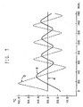
- FIGS. 4 to 6 A designates the set point temperature of a fluid sample.
- B denotes the detected temperature of the fluid sample
- C the set point temperature of a liquid bath, calculated by the aforementioned first controller
- D the detected temperature of the liquid bath.
- FIGS. 4 to 6 show experimental results obtained by using fluid samples which have a low viscosity and a high heat conductivity relative to those of the fluid sample used in the experiment the result of which is shown in FIG. 4.
- the set point temperature C of the liquid bath is adjusted to be higher or lower by 5 degrees Celsius than the corresponding set point temperature of the fluid sample according to the temperature controlling program as shown in FIG. 3(b).
- FIG. 7 shows an experimental result when the operation of the heating and cooling means 18 is controlled according to a PID controlled signal formed, on the basis of the difference between the set point temperature of a fluid sample and its detected temperature, in the second controller 17.
- the first controller 13 is not used, and the signals corresponding to the set point temperature of the fluid sample and its detected temperature are directly inputted into the second controller 17, where the detected temperature of a liquid bath is not fed back to the second controller 17.
- the temperature D of the liquid bath repeatedly considerably fluctuates with time, and thereby the temperature B of the fluid sample also waves with a considerable delay of response and does not approach its set point even after a long time.
Landscapes
- Engineering & Computer Science (AREA)
- Physics & Mathematics (AREA)
- General Physics & Mathematics (AREA)
- Automation & Control Theory (AREA)
- Analytical Chemistry (AREA)
- Health & Medical Sciences (AREA)
- Life Sciences & Earth Sciences (AREA)
- Chemical & Material Sciences (AREA)
- Remote Sensing (AREA)
- Biochemistry (AREA)
- General Health & Medical Sciences (AREA)
- Immunology (AREA)
- Pathology (AREA)
- Control Of Temperature (AREA)
- Investigating Or Analyzing Materials Using Thermal Means (AREA)
- Devices For Medical Bathing And Washing (AREA)
Claims (7)
- Dispositif de réglage de température destiné à régler la température d'un échantillon de fluide (3) situé dans un bain (8) de liquide, comportant des premiers moyens (11) pour mesurer la température d'un échantillon de fluide (3) situé dans un bain (8) de liquide,
des deuxièmes moyens pour déterminer. la différence entre une température d'échantillon voulue (14) et la température d'échantillon mesurée,
des troisièmes moyens (13) pour déterminer une température de bain voulue en fonction de la différence déterminée par lesdits deuxièmes moyens,
des quatrièmes moyens pour déterminer la différence entre la température de bain voulue et la température d'échantillon voulue,
des cinquièmes moyens (15) pour mesurer la température réelle du bain,
des sixièmes moyens (17) pour déterminer la différence entre la température de bain voulue déterminée par lesdits troisièmes moyens et la température réelle du bain mesurée par lesdits cinquièmes moyens, et
des septièmes moyens (18) pour chauffer ou refroidir le bain de liquide en fonction de la différence déterminée par les sixièmes moyens pour obtenir une différence nulle, caractérisé en ce que :
lesdits troisièmes moyens (13) comportent des moyens sélectifs pour déterminer de manière sélective la température de bain voulue selon une première fonction de la différence déterminée par lesdits deuxièmes moyens lorsque la valeur absolue de la différence déterminée par lesdits deuxièmes moyens est plus grande qu'une valeur prédéterminée et selon une seconde fonction de la différence déterminée par lesdits deuxièmes moyens lorsque la valeur absolue de la différence déterminée par lesdits deuxièmes moyens n'est pas plus grande que la valeur prédéterminée, ledit dispositif de réglage de température comporte en outre des moyens de limitation destinés à limiter la température de bain voulue déterminée par lesdits moyens sélectifs à la température d'échantillon voulue plus une valeur de température donnée lorsque la différence déterminée par lesdits quatrièmes moyens est plus grande que la valeur donnée et à la température d'échantillon voulue moins la valeur donnée lorsque la différence déterminée par lesdits quatrièmes moyens est plus petite que la valeur négative de la valeur donnée, et
lesdits sixièmes moyens (17) comportent des moyens pour déterminer la différence entre la température de bain voulue déterminée par lesdits moyens sélectifs et lesdits moyens de limitation et la température réelle du bain mesurée par lesdits cinquièmes moyens (15). - Procédé pour régler la température d'un échantillon de fluide situé dans un bain de liquide, comportant les étapes consistant à :(1) mesurer la température d'un échantillon de fluide situé dans un bain de liquide,(2) déterminer la différence entre une température d'échantillon voulue et la température d'échantillon mesurée,(3) déterminer une température de bain voulue en fonction de la différence déterminée à l'étape (2),(4) déterminer la différence entre la température de bain voulue et la température d'échantillon voulue,(5) mesurer la température réelle du bain,(6) déterminer la différence entre la température de bain voulue déterminée à l'étape (3) et la température réelle du bain mesurée à l'étape (5), et(7) chauffer ou refroidir le bain de liquide en fonction de la différence déterminée à l'étape (6) pour obtenir une différence nulle, caractérisé en ce que :ladite étape (3) comporte un étape sélective consistant à déterminer de manière sélective la température de bain voulue en fonction d'une première fonction de la différence déterminée dans ladite étape (2) lorsque la valeur absolue de la différence déterminée dans ladite étape (2) est plus grande qu'une valeur prédéterminée et selon une seconde fonction de la différence déterminée à l'étape (2) lorsque la valeur absolue de la différence déterminée à l'étape (2) n'est pas plus grande que la valeur prédéterminée,
ledit procédé de réglage de température comporte en outre une étape consistant à limiter la température de bain voulue déterminée à ladite étape sélective à la température d'échantillon voulue plus une valeur donnée de température lorsque la différence déterminée à l'étape (4) est plus grande que la valeur donnée et à la température d'échantillon voulue moins la valeur donnée lorsque la différence déterminée à l'étape (4) est plus petite que la valeur négative de la valeur donnée, et ladite étape (6) comporte une étape consistant à déterminer la différence entre la température de bain voulue déterminée dans ladite étape sélective et ladite étape de limitation et la température réelle du bain mesurée dans ladite étape (5). - Procédé selon la revendication 2, caractérisé en ce que ladite première fonction est définie par

TbS = température voulue pour le bain de liquide,
TS = température voulue pour l'échantillon de liquide,
MS(i) = température mesurée de l'échantillon de fluide
dans la iième répétition, et
Kp = constante proportionnelle. - Procédé selon la revendication 2, caractérisé en ce que la seconde fonction est définie par

TbS = température voulue pour le bain de liquide,
TS = température voulue pour l'échantillon de liquide,
τ = période de commande définie comme l'intervalle de temps existant entre les répétitions successives de détermination de TbS,
MS(i) et MS(j) sont les températures mesurées de l'échantillon de fluide dans respectivement la iième répétition et la jième répétition, de la période de commande τ,
Kp = constante proportionnelle,
KI = constante d'intégration. - Procédé selon la revendication 2, caractérisé en ce que ladite valeur prédéterminée dans ladite étape sélective est égale à 2 degrés Celsius.
- Procédé selon la revendication 2, caractérisé en ce que ladite valeur de température donnée dans ladite étape de limitation est égale à 5 degrés Celsius.
- Procédé selon la revendication 2, caractérisé en ce que ladite période de commande est égale à 10 secondes.
Applications Claiming Priority (2)
| Application Number | Priority Date | Filing Date | Title |
|---|---|---|---|
| US440402 | 1989-11-17 | ||
| US07/440,402 US4993480A (en) | 1989-02-01 | 1989-11-17 | Temperature controlling means for a thermostat for use in measuring viscosity |
Publications (3)
| Publication Number | Publication Date |
|---|---|
| EP0432864A2 EP0432864A2 (fr) | 1991-06-19 |
| EP0432864A3 EP0432864A3 (fr) | 1991-06-26 |
| EP0432864B1 true EP0432864B1 (fr) | 1994-06-01 |
Family
ID=23748620
Family Applications (1)
| Application Number | Title | Priority Date | Filing Date |
|---|---|---|---|
| EP90303427A Expired - Lifetime EP0432864B1 (fr) | 1989-11-17 | 1990-03-30 | Dispositif de contrôle de la température |
Country Status (5)
| Country | Link |
|---|---|
| US (1) | US4993480A (fr) |
| EP (1) | EP0432864B1 (fr) |
| KR (1) | KR920006976B1 (fr) |
| CA (1) | CA2025946C (fr) |
| DE (2) | DE69009412T2 (fr) |
Families Citing this family (12)
| Publication number | Priority date | Publication date | Assignee | Title |
|---|---|---|---|---|
| JP2644896B2 (ja) * | 1989-09-18 | 1997-08-25 | 株式会社日立製作所 | 冷却装置の温度制御方法 |
| KR940005572B1 (ko) * | 1992-02-01 | 1994-06-21 | 삼성전자 주식회사 | 김치냉장고의 김치 숙성저장제어장치 및 방법 |
| DE4239232A1 (de) * | 1992-11-21 | 1994-05-26 | Schubert Werner | Vorrichtung und Verfahren für die Wärmedenaturierung frischen Gewebes im histologischen Labor |
| DE19815074A1 (de) * | 1998-03-12 | 1999-10-07 | Stefan Novotny | Labor-Temperiergerät |
| US6164557A (en) * | 1998-04-30 | 2000-12-26 | Sioux Steam Cleaner Corporation | Fluid temperature control for a heated fluid cleaner with multiple outlets |
| US6424873B1 (en) * | 1999-12-30 | 2002-07-23 | Honeywell Inc. | Systems and methods for limiting integral calculation components in PID controllers |
| US7655003B2 (en) * | 2005-06-22 | 2010-02-02 | Smith & Nephew, Inc. | Electrosurgical power control |
| US20120230661A1 (en) * | 2008-11-11 | 2012-09-13 | Emerson Electric Co. | Apparatus and Method for Control of a Thermostat |
| US9398640B2 (en) * | 2012-12-21 | 2016-07-19 | Halliburton Energy Services, Inc. | Digital multi-use thermo-cup |
| EP3427120A4 (fr) * | 2016-03-07 | 2019-03-20 | Michael R. Bonner | Module de régulation de la viscosité par manipulation de la température |
| JP6720752B2 (ja) * | 2016-07-25 | 2020-07-08 | 富士通株式会社 | 液浸冷却装置、液浸冷却システム、及び液浸冷却装置の制御方法 |
| DE102023131167A1 (de) * | 2023-11-09 | 2025-05-15 | Burkert Australia Pty Ltd | Flüssigkeitsbehandlungsvorrichtung und Verfahren zum Behandeln einer Flüssigkeit |
Family Cites Families (12)
| Publication number | Priority date | Publication date | Assignee | Title |
|---|---|---|---|---|
| US2876327A (en) * | 1956-10-24 | 1959-03-03 | Standard Oil Co | Temperature controller |
| US3770946A (en) * | 1971-02-25 | 1973-11-06 | Leeds & Northrup Co | Method for automatic control with time varying tuning |
| US3824479A (en) * | 1972-08-16 | 1974-07-16 | Harrel Inc | Controller with digital integration |
| GB1603825A (en) * | 1977-05-17 | 1981-12-02 | Jones K R | Three term (pid) controllers |
| US4232364A (en) * | 1978-12-18 | 1980-11-04 | Honeywell Inc. | Adaptive sampled-data controller |
| US4368510A (en) * | 1980-10-20 | 1983-01-11 | Leeds & Northrup Company | Automatic identification system for self tuning process controller |
| US4407013A (en) * | 1980-10-20 | 1983-09-27 | Leeds & Northrup Company | Self tuning of P-I-D controller by conversion of discrete time model identification parameters |
| US4625096A (en) * | 1984-10-01 | 1986-11-25 | American Hospital Supply Corporation | Liquid bath temperature control |
| JPS6194104A (ja) * | 1984-10-04 | 1986-05-13 | Taiheiyo Kogyo Kk | Pid制御装置 |
| JPS61128303A (ja) * | 1984-11-27 | 1986-06-16 | Mitsubishi Electric Corp | 比例積分装置 |
| JPS61160102A (ja) * | 1984-12-29 | 1986-07-19 | Nishihara Environ Sanit Res Corp | プロセス制御装置 |
| US4734872A (en) * | 1985-04-30 | 1988-03-29 | Temptronic Corporation | Temperature control for device under test |
-
1989
- 1989-11-17 US US07/440,402 patent/US4993480A/en not_active Expired - Fee Related
-
1990
- 1990-03-30 DE DE69009412T patent/DE69009412T2/de not_active Expired - Fee Related
- 1990-03-30 EP EP90303427A patent/EP0432864B1/fr not_active Expired - Lifetime
- 1990-03-30 DE DE199090303427T patent/DE432864T1/de active Pending
- 1990-05-09 KR KR1019900006502A patent/KR920006976B1/ko not_active Expired
- 1990-09-21 CA CA002025946A patent/CA2025946C/fr not_active Expired - Fee Related
Also Published As
| Publication number | Publication date |
|---|---|
| DE432864T1 (de) | 1992-03-19 |
| EP0432864A3 (fr) | 1991-06-26 |
| US4993480A (en) | 1991-02-19 |
| KR920006976B1 (ko) | 1992-08-22 |
| CA2025946C (fr) | 1994-04-12 |
| KR910020535A (ko) | 1991-12-20 |
| DE69009412D1 (de) | 1994-07-07 |
| EP0432864A2 (fr) | 1991-06-19 |
| CA2025946A1 (fr) | 1991-05-18 |
| DE69009412T2 (de) | 1994-09-29 |
Similar Documents
| Publication | Publication Date | Title |
|---|---|---|
| EP0432864A2 (fr) | Dispositif de contrôle de la température | |
| GB2122347A (en) | Improvements in or relating to methods of and apparatuses for determining heat transfer coefficients | |
| EP0244268A2 (fr) | Dispositif de commande de puissance pour commande de température | |
| EP0335904B1 (fr) | Dispositif electronique multi-phase de controle de la temperature | |
| EP0321210A2 (fr) | Calorimètre automatique et méthodes pour le faire fonctionner | |
| JP2004012462A (ja) | 物質の熱的調査方法及び装置 | |
| JPH0259417B2 (fr) | ||
| Hollasch et al. | Calibration of constant-temperature hot-wire anemometers at low velocities in water with variable fluid temperature | |
| JPH0229984B2 (fr) | ||
| EP0213837A2 (fr) | Régulateur de température modulaire | |
| CA1332292C (fr) | Mecanisme de controle de la temperature destine a un thermostat utilise pour mesurer la viscosite | |
| JPH0481638A (ja) | 恒温槽による流体試料温度制御装置 | |
| KR920009890B1 (ko) | 점도 측정용 항온조의 온도 제어수단 | |
| RU2010191C1 (ru) | Способ определения погрешностей термоэлектрических термометров | |
| US8150558B2 (en) | Temperature control method and temperature controller | |
| Lahti et al. | Polymerization calorimeter. Part 1. Modelling and characterization | |
| JP2964186B2 (ja) | 熱式流量計 | |
| Barić et al. | Measurement and Modelling of the Thermal Response of the Resistance Temperature Sensors | |
| Bonvin et al. | On line procedures for supervising the operation of batch reactors | |
| Fujieda et al. | Microcomputer-aided control system for a precision water bath in the heat-exchange calorimeter | |
| JPH0259418B2 (fr) | ||
| JPH0259419B2 (fr) | ||
| Larkin et al. | ERROR ANALYSIS IN ESTIMATING THERMAL DIFFUSIVITY FROM HEAT PENETRATION DATA 1 | |
| GB2131953A (en) | Measuring the viscosity and elasticity of fluids, particularly polymers | |
| EP3246783A2 (fr) | Procédé de régulation de température à correction aval adaptatif |
Legal Events
| Date | Code | Title | Description |
|---|---|---|---|
| PUAI | Public reference made under article 153(3) epc to a published international application that has entered the european phase |
Free format text: ORIGINAL CODE: 0009012 |
|
| PUAL | Search report despatched |
Free format text: ORIGINAL CODE: 0009013 |
|
| AK | Designated contracting states |
Kind code of ref document: A2 Designated state(s): CH DE FR GB IT LI SE |
|
| AK | Designated contracting states |
Kind code of ref document: A3 Designated state(s): CH DE FR GB IT LI SE |
|
| ITCL | It: translation for ep claims filed |
Representative=s name: BARZANO' E ZANARDO ROMA S.P.A. |
|
| 17P | Request for examination filed |
Effective date: 19911204 |
|
| EL | Fr: translation of claims filed | ||
| DET | De: translation of patent claims | ||
| K1C3 | Correction of patent application (complete document) published |
Effective date: 19910619 |
|
| 17Q | First examination report despatched |
Effective date: 19921218 |
|
| GRAA | (expected) grant |
Free format text: ORIGINAL CODE: 0009210 |
|
| ITF | It: translation for a ep patent filed | ||
| AK | Designated contracting states |
Kind code of ref document: B1 Designated state(s): CH DE FR GB IT LI SE |
|
| REF | Corresponds to: |
Ref document number: 69009412 Country of ref document: DE Date of ref document: 19940707 |
|
| ET | Fr: translation filed | ||
| EAL | Se: european patent in force in sweden |
Ref document number: 90303427.0 |
|
| PGFP | Annual fee paid to national office [announced via postgrant information from national office to epo] |
Ref country code: SE Payment date: 19950310 Year of fee payment: 6 |
|
| PGFP | Annual fee paid to national office [announced via postgrant information from national office to epo] |
Ref country code: FR Payment date: 19950320 Year of fee payment: 6 |
|
| PLBE | No opposition filed within time limit |
Free format text: ORIGINAL CODE: 0009261 |
|
| STAA | Information on the status of an ep patent application or granted ep patent |
Free format text: STATUS: NO OPPOSITION FILED WITHIN TIME LIMIT |
|
| PGFP | Annual fee paid to national office [announced via postgrant information from national office to epo] |
Ref country code: CH Payment date: 19950406 Year of fee payment: 6 |
|
| 26N | No opposition filed | ||
| PG25 | Lapsed in a contracting state [announced via postgrant information from national office to epo] |
Ref country code: SE Effective date: 19960331 Ref country code: LI Effective date: 19960331 Ref country code: CH Effective date: 19960331 |
|
| REG | Reference to a national code |
Ref country code: CH Ref legal event code: PL |
|
| PG25 | Lapsed in a contracting state [announced via postgrant information from national office to epo] |
Ref country code: FR Effective date: 19961129 |
|
| EUG | Se: european patent has lapsed |
Ref document number: 90303427.0 |
|
| REG | Reference to a national code |
Ref country code: FR Ref legal event code: ST |
|
| REG | Reference to a national code |
Ref country code: GB Ref legal event code: 732E |
|
| PGFP | Annual fee paid to national office [announced via postgrant information from national office to epo] |
Ref country code: GB Payment date: 20000323 Year of fee payment: 11 |
|
| PGFP | Annual fee paid to national office [announced via postgrant information from national office to epo] |
Ref country code: DE Payment date: 20000328 Year of fee payment: 11 |
|
| PG25 | Lapsed in a contracting state [announced via postgrant information from national office to epo] |
Ref country code: GB Free format text: LAPSE BECAUSE OF NON-PAYMENT OF DUE FEES Effective date: 20010330 |
|
| GBPC | Gb: european patent ceased through non-payment of renewal fee |
Effective date: 20010330 |
|
| PG25 | Lapsed in a contracting state [announced via postgrant information from national office to epo] |
Ref country code: DE Free format text: LAPSE BECAUSE OF NON-PAYMENT OF DUE FEES Effective date: 20020101 |
|
| PG25 | Lapsed in a contracting state [announced via postgrant information from national office to epo] |
Ref country code: IT Free format text: LAPSE BECAUSE OF NON-PAYMENT OF DUE FEES;WARNING: LAPSES OF ITALIAN PATENTS WITH EFFECTIVE DATE BEFORE 2007 MAY HAVE OCCURRED AT ANY TIME BEFORE 2007. THE CORRECT EFFECTIVE DATE MAY BE DIFFERENT FROM THE ONE RECORDED. Effective date: 20050330 |