EP0432958A1 - Procédé pour la fabrication d'un cylindre perforé sans soudure - Google Patents
Procédé pour la fabrication d'un cylindre perforé sans soudure Download PDFInfo
- Publication number
- EP0432958A1 EP0432958A1 EP90313193A EP90313193A EP0432958A1 EP 0432958 A1 EP0432958 A1 EP 0432958A1 EP 90313193 A EP90313193 A EP 90313193A EP 90313193 A EP90313193 A EP 90313193A EP 0432958 A1 EP0432958 A1 EP 0432958A1
- Authority
- EP
- European Patent Office
- Prior art keywords
- slots
- forming
- cylinder
- slot
- holes
- Prior art date
- Legal status (The legal status is an assumption and is not a legal conclusion. Google has not performed a legal analysis and makes no representation as to the accuracy of the status listed.)
- Withdrawn
Links
Images

Classifications
-
- B—PERFORMING OPERATIONS; TRANSPORTING
- B01—PHYSICAL OR CHEMICAL PROCESSES OR APPARATUS IN GENERAL
- B01D—SEPARATION
- B01D29/00—Filters with filtering elements stationary during filtration, e.g. pressure or suction filters, not covered by groups B01D24/00 - B01D27/00; Filtering elements therefor
- B01D29/11—Filters with filtering elements stationary during filtration, e.g. pressure or suction filters, not covered by groups B01D24/00 - B01D27/00; Filtering elements therefor with bag, cage, hose, tube, sleeve or like filtering elements
- B01D29/111—Making filtering elements
-
- B—PERFORMING OPERATIONS; TRANSPORTING
- B01—PHYSICAL OR CHEMICAL PROCESSES OR APPARATUS IN GENERAL
- B01D—SEPARATION
- B01D29/00—Filters with filtering elements stationary during filtration, e.g. pressure or suction filters, not covered by groups B01D24/00 - B01D27/00; Filtering elements therefor
- B01D29/11—Filters with filtering elements stationary during filtration, e.g. pressure or suction filters, not covered by groups B01D24/00 - B01D27/00; Filtering elements therefor with bag, cage, hose, tube, sleeve or like filtering elements
- B01D29/31—Self-supporting filtering elements
- B01D29/33—Self-supporting filtering elements arranged for inward flow filtration
-
- B—PERFORMING OPERATIONS; TRANSPORTING
- B23—MACHINE TOOLS; METAL-WORKING NOT OTHERWISE PROVIDED FOR
- B23K—SOLDERING OR UNSOLDERING; WELDING; CLADDING OR PLATING BY SOLDERING OR WELDING; CUTTING BY APPLYING HEAT LOCALLY, e.g. FLAME CUTTING; WORKING BY LASER BEAM
- B23K26/00—Working by laser beam, e.g. welding, cutting or boring
- B23K26/36—Removing material
- B23K26/362—Laser etching
- B23K26/364—Laser etching for making a groove or trench, e.g. for scribing a break initiation groove
-
- B—PERFORMING OPERATIONS; TRANSPORTING
- B23—MACHINE TOOLS; METAL-WORKING NOT OTHERWISE PROVIDED FOR
- B23K—SOLDERING OR UNSOLDERING; WELDING; CLADDING OR PLATING BY SOLDERING OR WELDING; CUTTING BY APPLYING HEAT LOCALLY, e.g. FLAME CUTTING; WORKING BY LASER BEAM
- B23K26/00—Working by laser beam, e.g. welding, cutting or boring
- B23K26/36—Removing material
- B23K26/38—Removing material by boring or cutting
- B23K26/382—Removing material by boring or cutting by boring
- B23K26/384—Removing material by boring or cutting by boring of specially shaped holes
-
- B—PERFORMING OPERATIONS; TRANSPORTING
- B23—MACHINE TOOLS; METAL-WORKING NOT OTHERWISE PROVIDED FOR
- B23K—SOLDERING OR UNSOLDERING; WELDING; CLADDING OR PLATING BY SOLDERING OR WELDING; CUTTING BY APPLYING HEAT LOCALLY, e.g. FLAME CUTTING; WORKING BY LASER BEAM
- B23K26/00—Working by laser beam, e.g. welding, cutting or boring
- B23K26/50—Working by transmitting the laser beam through or within the workpiece
- B23K26/53—Working by transmitting the laser beam through or within the workpiece for modifying or reforming the material inside the workpiece, e.g. for producing break initiation cracks
-
- B—PERFORMING OPERATIONS; TRANSPORTING
- B23—MACHINE TOOLS; METAL-WORKING NOT OTHERWISE PROVIDED FOR
- B23K—SOLDERING OR UNSOLDERING; WELDING; CLADDING OR PLATING BY SOLDERING OR WELDING; CUTTING BY APPLYING HEAT LOCALLY, e.g. FLAME CUTTING; WORKING BY LASER BEAM
- B23K31/00—Processes relevant to this subclass, specially adapted for particular articles or purposes, but not covered by any single one of main groups B23K1/00 - B23K28/00
- B23K31/02—Processes relevant to this subclass, specially adapted for particular articles or purposes, but not covered by any single one of main groups B23K1/00 - B23K28/00 relating to soldering or welding
- B23K31/025—Connecting cutting edges or the like to tools; Attaching reinforcements to workpieces, e.g. wear-resisting zones to tableware
-
- D—TEXTILES; PAPER
- D21—PAPER-MAKING; PRODUCTION OF CELLULOSE
- D21D—TREATMENT OF THE MATERIALS BEFORE PASSING TO THE PAPER-MAKING MACHINE
- D21D5/00—Purification of the pulp suspension by mechanical means; Apparatus therefor
- D21D5/02—Straining or screening the pulp
- D21D5/16—Cylinders and plates for screens
-
- Y—GENERAL TAGGING OF NEW TECHNOLOGICAL DEVELOPMENTS; GENERAL TAGGING OF CROSS-SECTIONAL TECHNOLOGIES SPANNING OVER SEVERAL SECTIONS OF THE IPC; TECHNICAL SUBJECTS COVERED BY FORMER USPC CROSS-REFERENCE ART COLLECTIONS [XRACs] AND DIGESTS
- Y10—TECHNICAL SUBJECTS COVERED BY FORMER USPC
- Y10T—TECHNICAL SUBJECTS COVERED BY FORMER US CLASSIFICATION
- Y10T29/00—Metal working
- Y10T29/49—Method of mechanical manufacture
- Y10T29/496—Multiperforated metal article making
- Y10T29/49604—Filter
Definitions
- Screen cylinders are formed by machining the required slots or grooves in a flat plate of metal material, such as stainless steel, and then rolling the material into the shape of a cylinder, and welding the rolled plate at the abutting ends to form a welded seam. Thereafter end rings, formed from bar stock, are rolled, welded at their respective ends, and attached by welding to the cylinder plate, at its respective ends. One or more intermediate reinforcing rings, also formed from rolled bar stock, are attached by welding at longitudinally spaced locations on the outer surface of the rolled screen plate.
- An example of such a fabricated cylinder screen is shown in Hatton et al, U. S. 4,017,387, issued April 12, 1977. Such cylinders are subject to fatigue failures.
- This invention includes a centrifugally cast body, which is initially cast approximately to the desired finished shape.
- Centrifugal casting techniques provide a product having superior uniformity of grain structure and superior dimensional tolerance as to roundness, in cylindrical metal parts. Where end rings and/or intermediate reinforcing rings or ribs are required, they are cast in place during the centrifugal casting. After casting, the cast part may be machined to a high degree of accuracy about a true center, and thereby provides a seamless body which is inherently free of internal stresses, and has a uniform and coherent grain structure.
- An alternative method of making the seamless basic body or cylinder is by cold working a seamless blank using a roller extrusion process. If end rings and/or intermediate reinforcing rings or ribs are desired, they may be formed during the cold working.
- the starting workpiece may be a centrifugal casting.
- the piece is cold worked by the roller extrusion process, as practiced as a proprietary process by Kaiser Rollmet Division of Kaiser Aerospace & Electronics Company, 1822 Deer Avenue, Irvine, California.
- Such a cold worked screen is seamless and is characterized by a higher strength as compared to an "as cast" material.
- the "Rollmet” process provides a precision seamless cylindrical shape which is uniquely suited for the production of thin walled and complex cylindrical shapes in diameters from 4 inches up to 72 inches.
- the process results in a fine grain structure which results from the combination of cold working of the metal plus re-crystallization and work hardening.
- the work piece can therefore be a blank cylinder of required specifications with respect to wall thickness and length, taking into the account the radial and axial expansion inherent in the radial forging process to arrive at a desired wall thickness and axial length in the finished product, as is known in this art.
- Two methods of radial forging are available.
- An alternative process is available by which outside rollers operate in conjunction with a mandrel so that as the blank is rotated and pulled through the rollers, the I.D. remains constant while the wall thickness and the O.D. is reduced. In either technique, a truly cylindrical wall is formed to accurate dimensions and is simultaneously cold worked to increase the strength over its "as cast" condition.
- the openings or slots are formed by a laser cutting technique, by focusing a laser cutting beam or by directing such laser beam energy, at the outlet surface toward the inlet surface as shown in U. S. Patent No. 4,795,560.
- the cylinder and/or the beam may be moved in relation to the other.
- the high degree of accuracy of the roundness or trueness of the centrifugal cast product permits the laser cutting head to be positioned in close relation to the outer surface to be cut while one or the other is moved. The need to program for an out-of-round condition is reduced or eliminated.
- turbulence inducing bars also known as "wear” bars, may be applied along the inside surface of the cylinder, either before or after laser cutting, such as by welding a bead as shown in U. S. Patent No. 4,795,560. The welding of a surface bead does not create an inherent weakness since the weld does not excessively penetrate the thickness of the wall material, and since the wear bars do not carry a load.
- the roller extrusion cold work process or the centrifugal casting process permits the manufacture of screen cylinder bodies of more than one material.
- the main portion of such a body may be formed of basic stainless steel, and an inside wear surface of a harder or more wear resistant material may be used. In casting, the harder inside material is added after the body is cast of the basic material.
- the invention may be described as a method of manufacturing a screen cylinder for removing contaminant particles from papermaking stock in which a cylinder body is formed with an intermediate cylindrical section and in which a plurality of closely spaced screening holes or slots are formed in the cylindrical section, characterized by the steps of forming the cylinder body as an integral seamless unit free or devoid of internal stresses, and at the same time forming the intermediate section of the body with a generally uniform radial thickness throughout the intermediate section to define an inner surface and an outer surface, and forming the holes or slots by directing a focused laser beam at the outer surface of the cylindrical section, thereby forming a hole or slot with tapered walls.
- the invention may be further characterized by the steps of forming the cylindrical body with a pair of end rings which are integral with the body and at least one intermediate reinforcing rib also integral with the body and positioned on the outer surface of the intermediate section between the end rings, and in which the holes or slots are formed in spaces between the rib and the end rings.
- the method may also be further characterized by the step of moving the cylinder body with respect to the laser beam to form or cut slots through the intermediate section.
- the body may be formed by the steps of centrifugally casting or by the steps of cold roller extrusion.
- the method according to this invention may be further characterized by the steps of focusing the laser beam at or against the outer surface of the body and positioning the focus at a point or region which is intermediate or between the outer and inner surfaces of the intermediate section, adjacent or close to the inner surface, to form a hole or a slot which has tapered walls, and in which the walls are wider apart at the outer surface than they are at the inner surface.
- the invention may be further characterized by the steps of applying wear bars, by applying beads of weld material, by welding the beads to the inner surface of the cylindrical body so that the wear bars do not intersect the holes or slots formed therethrough.
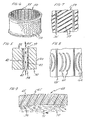
- Fig. 1 is a perspective view of a body of a screen cylinder which has been made either by centrifugal casting or by cold roller extrusion.
- Fig. 2 is an enlarged fragmentary detail of a portion of the screen side wall after the slots have been cut and wear bars applied, looking at an inside surface;
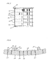
- Fig. 3 is a view of a finished cylinder screen according to this invention, partially in section;
- Fig. 4 is a fragmentary section through the side wall;
- Fig. 5 is an enlarged sectional view through one of the slots;
- Fig. 6 is a somewhat diagrammatic view of a screen cylinder according to this invention showing a chevron slot arrangement;
- Fig. 1 is a perspective view of a body of a screen cylinder which has been made either by centrifugal casting or by cold roller extrusion.
- Fig. 2 is an enlarged fragmentary detail of a portion of the screen side wall after the slots have been cut and wear bars applied, looking at an inside surface
- FIG. 7 is an enlarged inside elevational view showing another slot arrangement
- Fig. 8 is a view similar to Fig. 7 showing a still different arrangement of slots
- Fig. 9 is an enlarged fragmentary section of the wall of the cylinder showing the formation of inclined holes or slots slopping with the direction of movement of the stock.
- a body 10 of a screening cylinder body 10 is shown as made according to this invention.
- the body 10 may be a finished centrifugal casting, which is cast initially to the desired size and which may have a finished or machined inner and/or outer surface as required.
- Such an "as cast" blank is inherently free of internal stresses and is characterized by a uniform grain pattern throughout.
- the blank is entirely seamless, and free or devoid of any welds which could form high stress points or points of weakness.
- the techniques for centrifugally casting of cylindrical bodies are well known in the art, and reference may be had to U. S. Patents Nos. 2,843,755, 4,124,056, 3,293,708, and 743,077. Either vertical or horizontal centrifugal casting techniques may be used as well known in the industry.
- the body 10 may be cold worked.
- a centrifugal cast blank is employed, in the shape of a simple cylinder, with a controlled inside or outside diameter, and is radially cold worked by inside roller pressure against an outside mandrel or outside roller pressure against an inside mandrel, as known as the "Roll Extrusion" process practiced by Kaiser Rollmet Division, Kaiser Aerospace & Electronics Company, 1822 Deer Avenue, Irvine, California.
- a central or intermediate cylindrical screening portion 12 of defined thickness is formed with accurately spaced inner and outer surfaces.
- a first integral end ring 14 is formed on one end and a second integral end ring 15 formed on the opposite axial end thereof, as may be required for utilization in the particular screening apparatus.
- the body 10, during forming, may also be provided with one or more intermediate enforcing rings 16.
- the entire body 10 is centrifugally cast to the finished size, after casting it may be surface finished, at least on the inside surface, by a machine tool to remove any residual slag and/or irregularities, and to provide a cylindrically true surface along the inside surface.
- the end rings 14 and 15, and the intermediate rings 16, are not separate or discrete elements, such as shown in patent 4,017,387, but are unitary and integral parts of the body 10 itself, and thus are integral with the intermediate cylindrical portion 12 and the generally cylindrical side wall 20 defined by this section.
- the side wall 20, as shown in Figs. 2 and 4 is formed with a generally uniform thickness throughout, in the axial regions between the reinforcing rings, such as between an intermediate ring 16 and an adjacent end ring 14 or 15.
- the configurations of the end rings 14 and 15 permit the completed screen cylinder to be received within suitable high turbulence paper stock screening apparatus, of the general type as shown in Seifert, U. S. Patent No. 3,849,302 issued November 19, 1974 and the patent of Chupka and Seifert, U. S. Patent No. 4,155,841.
- suitable high turbulence paper stock screening apparatus of the general type as shown in Seifert, U. S. Patent No. 3,849,302 issued November 19, 1974 and the patent of Chupka and Seifert, U. S. Patent No. 4,155,841.
- Different models of such high pressure screening apparatus will require different overall screen cylinder configurations, within the scope of this invention, and as such may or may not have end or intermediate rings, or may have rings of a
- the body 10 is free of any connecting seams and is devoid of any rolled or bent parts which would contain or which would induce residual stresses within the body. In fact, the body 10 is substantially free of internal stresses, is of a uniform grain structure throughout, and exhibits a high strength.
- Openings are formed in the side wall 20 by laser cutting.
- the openings, illustrated by the slots 25, are formed in the intermediate wall portions 26 (Fig. 3) defined between the rings 16.
- Fig. 1 illustrates the body 10 before the cutting of the openings 25 and represents a form of the invention which may be pre-manufactured and stored for subsequent cutting to a customer's specification. Since a customer's specifications may vary, the laser cutting technique of this invention, in combination with the wear bar application technique of this invention, provides a high degree of versatility in the meeting of specific customer requirements.
- the cylinder body 10 as shown in Fig. 3, is formed with circumferential rows of generally axially oriented slots 25, the rows being positioned in the wall portions 26 between the reinforcing rings 16.
- the slots 25 in each of the annular bands or rows are formed into individual slot groups 28 defining axially extending land areas 29 therebetween, as shown in Fig. 4.
- the individual slots 25, as shown, extend through the wall 20 of the body portion, through an inner or inlet surface 30 to an outside or outlet surface 32, as shown in Fig. 4, in generally normal relation to these surfaces.
- the intermediate land areas 29, between the groups 28 of slots, provide a convenient space for the application of turbulence inducing ribs or wear bars 35 on the inner surface 30.
- the bars 35 may run the full height of the plate body 10 along the inner surface 30, on the land areas 29, and thus extend across the several annular rows of slots 25 in non-intersecting relation to the slots.
- the wear bars 35 are spaced angularly about the body from each other and run in generally parallel relationship, axially of the inner or inside surface 30.
- the technique of applying the wear bars by the application of weld material directly to the inner surface permits the bars to be applied in other than straight lines and may be applied in curved regular or irregular patterns on such surface.
- the wear bars 35 are preferably applied to the inner surface 30 at the lands 29 before the slots are cut through the body wall 20, and consist of weld beads which are applied directly to the surface, such as by a t.i.g. welder, and may consist of extremely hard cobalt-chromium-tungsten alloy. Such alloy is sold by Union Carbide & Chemical Corporation under the trade name "Stellite.”
- the bars may be applied in a single pass or may be applied, one on top of the other, in two or more passes, to provide the desired elevation or thickness above the plate surface.
- the forming methods provide an inside surface with a high degree of cylindrical accuracy, and permits the rotating foils to run closer to the inlet surface 30 than heretofore possible, and thus makes possible the use of turbulence inducing bars 35 which may consist of a single pass or single layer of weld bead material applied to the surface.
- the application of the beads, by welding, results in minimum penetration of the depth of the material of the wall 20 of the plate 10, and does not adversely affect the resistance of the overall cylinder against fatigue failures due to the fact that the major portion of the underlying grain structure is not effected by the application of the wear bars 35.
- the individual openings, such as the slots 25, are formed by laser energy beam cutting, through the outlet or outer surface 32 toward and into the inner or inlet surface 30. While a CO2 laser may be used, it is preferred to use a pulsed YAG laser, in which the beam is directed against the outer surface 32 and is focused at a region adjacent and immediately inwardly of the inner or inlet surface 30, with respect to the depth or thickness of the wall 20. Since the beam enters the wall from the outlet side and exits the wall at the inlet side, and since the beam itself is focused substantially at the inlet side, the opening formed by the beam at the region of breakthrough at the inner surface 30 is narrower than the opening formed at the outer surface 32. The extent of relief or taper is defined essentially by the convergence of the beam, with the result that the wall of the opening has a minimum of taper.
- the slots may be as small as 0.002" or as less as 0.035" or more.
- the more critical dimension is that of the inlet opening or gap 38 of the individual slot 25, as shown in Fig. 4, which may, for example, be in the order of 0.010".
- Laser cutting of the slots provides a slot, in a 0.31" thickness plate, with an exit or outlet opening 39 of about 0.025", defined by generally straight walls 40. In this example, the total divergence of the walls is only in the order of 2.5°.
- the inlet opening 38 may be smaller or larger than 0.010", and the exit opening 39 may be as wide as 0.040" or more.
- the slots 25 are transversely spaced at a density of 6 to the inch, although a greater or fewer number of slots, either narrower or wider in transverse dimension may be formed, as desired.
- the screen cylinder and beam are moved with respect to each other in an axial direction, with reference to the axis of the cylinder, to form a slot in which the narrow end 38 of the slot opens at the inlet surface, and the wider end 39 of the slot opens at the outlet surface, as shown in Fig. 5.
- the walls 40 of the slots 25 are free of tool or machine marks.
- the slots 25 are characterized by walls 40 which have an extremely smooth and hard surface, thereby enhancing the efficiency of the screen. This is due to the fact that, during the cutting steps, the surfaces of the walls which define the slots are heated by the laser beam to a temperature as that a very thin exposed wall layer 42 (shown with exaggerated thickness in Fig. 5) is momentarily heated to a molten state. As the laser beam passes, the wall layer 42 rapidly cools due to the mass of material and the thinness of the layer which has been molten. The resulting coalescence forms a "glassy" or recast outer or exposed surface to the walls, which may undulate slightly, and which is very hard and free of tool marks. Thus, it has been found that these walls present a minimum of friction to the flow of stock therethrough with the result that the screen cylinder exhibits greater capacity as compared to cylinders in which the openings are conventionally cut or machined.
- the laser cutting of the openings or slots through the wall 20 of the body 10 does not induce any latent or inherent stresses and, on the contrary, the heating and cooling cycle of the material which immediately surrounds the opening relieves stresses.
- a screen cylinder may have one or more designs or patterns of slots or have slots which are inclined or sloping with respect to either an axial or a circumferential line.
- a screen cylinder 50 is illustrated in Fig. 6 in which the slots 52 are mutually inclined to each other and internested in a chevron-like pattern. Such a pattern can be formed by moving the screen plate in relation to the laser cutting tool as desired.
- Fig. 7 shows a screen 54 in which the slots 55 are generally parallel to each other but are inclined to the axis of the screen plate, and the slots in each of the groups or rows may be, if desired, aligned with the slots in the adjacent group or row to provide a spiral-like appearance.
- Fig. 8 shows arcuately curved slots 60. Adjacent groups of slots 62 may be provided with a curvature in the opposite direction, if desired.
- the holes or slots may be inclined as shown at 65 in the plate 68 of Fig. 9.
- the slurry 70 rotates within and along the inside surface 30 of the cylinder with a direction as represented by the arrow 71.
- the slots, or some of them, may be oppositely inclined. Openings or slots which are forwardly inclined increase the extraction efficiency by decreasing the head across the cylinder, and provide a screen cylinder with higher efficiency. Reverse inclined openings have the advantage of providing increased downstream cleanliness due to the superior ability of such openings to reject heavier and/or longer fibers and debris.
- any long or heavier fiber which enters the opening must first make a turn, with respect to the velocity vector, which turn may equal or exceed 90°, thereby making it more difficult for such a long or heavier reject to enter the opening.
Landscapes
- Engineering & Computer Science (AREA)
- Mechanical Engineering (AREA)
- Physics & Mathematics (AREA)
- Optics & Photonics (AREA)
- Chemical Kinetics & Catalysis (AREA)
- Plasma & Fusion (AREA)
- Chemical & Material Sciences (AREA)
- General Chemical & Material Sciences (AREA)
- Oil, Petroleum & Natural Gas (AREA)
- Paper (AREA)
- Filtering Materials (AREA)
- Combined Means For Separation Of Solids (AREA)
- Filtration Of Liquid (AREA)
- Laser Beam Processing (AREA)
Applications Claiming Priority (2)
| Application Number | Priority Date | Filing Date | Title |
|---|---|---|---|
| US450873 | 1989-12-14 | ||
| US07/450,873 US5064537A (en) | 1987-04-16 | 1989-12-14 | Seamless screen cylinder with laser cut openings |
Publications (1)
| Publication Number | Publication Date |
|---|---|
| EP0432958A1 true EP0432958A1 (fr) | 1991-06-19 |
Family
ID=23789861
Family Applications (1)
| Application Number | Title | Priority Date | Filing Date |
|---|---|---|---|
| EP90313193A Withdrawn EP0432958A1 (fr) | 1989-12-14 | 1990-12-05 | Procédé pour la fabrication d'un cylindre perforé sans soudure |
Country Status (4)
| Country | Link |
|---|---|
| US (1) | US5064537A (fr) |
| EP (1) | EP0432958A1 (fr) |
| JP (1) | JPH04308294A (fr) |
| CA (1) | CA2029515C (fr) |
Cited By (9)
| Publication number | Priority date | Publication date | Assignee | Title |
|---|---|---|---|---|
| WO1994029070A1 (fr) * | 1993-06-11 | 1994-12-22 | Minnesota Mining And Manufacturing Company | Dispositif de replication usines par laser |
| EP0701877A1 (fr) * | 1994-09-16 | 1996-03-20 | McNEIL-PPC, INC. | Procédé de perçage avec rayon laser défocalisé pour la fabrication d'un dispositif de visualisation d'étoffe |
| EP0708262A1 (fr) * | 1994-10-10 | 1996-04-24 | Joachim Prof. Dr.-Ing. Heinzl | Palier aérostatique et procédé de fabrication d'un palier aérostatique |
| WO1997022434A1 (fr) * | 1995-12-18 | 1997-06-26 | Mcneil-Ppc, Inc. | Procedes de perforation au laser pour produire des dispositifs de formation de textiles et de films |
| EP0705933A3 (fr) * | 1994-09-16 | 1997-10-01 | Mcneil Ppc Inc | Appareil pour la fabrication de tissus non-tissés en relief |
| WO2005080020A1 (fr) * | 2004-02-20 | 2005-09-01 | Pegoretti Marcos Rogerio | Procede permettant de creer des fentes dans des tuyaux |
| CN111347218A (zh) * | 2018-12-20 | 2020-06-30 | 广西盛誉糖机制造有限责任公司 | 一种筛网制作工艺 |
| CN112045308A (zh) * | 2020-09-24 | 2020-12-08 | 韩延辉 | 分瓣式大口径筛筒及其制造工艺 |
| CN116197622A (zh) * | 2023-03-10 | 2023-06-02 | 武汉一冶钢结构有限责任公司 | 一种风洞稳定段人孔门的制作方法 |
Families Citing this family (48)
| Publication number | Priority date | Publication date | Assignee | Title |
|---|---|---|---|---|
| US5200072A (en) * | 1990-08-16 | 1993-04-06 | Ahlstrom Screen Plates Inc. | Screen plates and methods of manufacture |
| FI89521C (fi) * | 1991-10-04 | 1993-10-11 | Cae Investments Bv | Foerfarande foer framstaellning av en silprodukt och genom foerfarandet framstaelld silprodukt |
| DE4308225C1 (de) * | 1993-03-16 | 1994-11-24 | Escher Wyss Gmbh | Verfahren zur Sortierung von Faserstoffsuspension sowie Siebvorrichtung zu seiner Durchführung |
| WO1995005248A1 (fr) * | 1993-08-16 | 1995-02-23 | The Black Clawson Company | Tamis a fente pour materiau de fabrication de papier |
| CA2111147A1 (fr) * | 1993-12-13 | 1995-06-14 | Jacques Riendeau | Methode servant a fabriquer un epurateur cylindrique, et epurateur ainsi obtenu |
| CN2203190Y (zh) * | 1994-05-20 | 1995-07-12 | 北京矿冶研究总院 | 一种筛笼型旋流细筛 |
| US5513757A (en) * | 1994-06-02 | 1996-05-07 | Sulzer Papertec Mansfield Inc. | Continuous cut slotted screen basket |
| US5564272A (en) * | 1994-07-29 | 1996-10-15 | Thiokol Corporation | Slotted hybrid pressure vessel |
| US5626753A (en) * | 1995-03-03 | 1997-05-06 | Zenere; David | System and method for the transport of lime |
| DE29506015U1 (de) * | 1995-04-07 | 1995-06-14 | Hosokawa Alpine Ag, 86199 Augsburg | Sichtrad für Schleuderrad-Windsichter |
| US5718826A (en) * | 1995-05-26 | 1998-02-17 | Cae Screen Plates, Inc. | Screen and method of manufacture |
| SE507471C2 (sv) * | 1996-08-09 | 1998-06-08 | Sunds Defibrator Ind Ab | Silpanel samt sätt för dess framställning |
| BE1010578A3 (nl) * | 1996-08-22 | 1998-10-06 | Heirwegh Etienne | Inrichting voor het sorteren van diverse materialen zoals o.m. grond en puin. |
| US6930277B2 (en) | 1997-09-10 | 2005-08-16 | Velcro Industries B.V. | Fastener element molding |
| US5884374A (en) * | 1997-11-20 | 1999-03-23 | Velcro Industries B.V. | Fastener members and apparatus for their fabrication |
| RU2137526C1 (ru) * | 1998-04-16 | 1999-09-20 | Государственное предприятие "НПО. Техномаш" | Дренажно-распределительное устройство ионообменного фильтра |
| US6460757B1 (en) * | 2000-11-14 | 2002-10-08 | Newscreen As | Apparatus and method for forming slotted wire screens |
| CA2444486C (fr) * | 2001-04-16 | 2013-04-02 | J & L Fiber Services, Inc. | Epurateur a pate a papier et son procede |
| US20030012833A1 (en) * | 2001-06-27 | 2003-01-16 | Freissle Manfred Franz Axel | Screening arrangement |
| JP2005505415A (ja) * | 2001-10-18 | 2005-02-24 | カデント ブラック クローソン インコーポレーテッド | レーザーまたは水ジェット切削開口を有する引出し台板 |
| DE10217926A1 (de) * | 2002-04-23 | 2003-11-13 | Voith Paper Patent Gmbh | Verfahren zum Nasssieben von Faserstoffsuspensionen |
| US7144479B2 (en) * | 2003-04-16 | 2006-12-05 | Albany International Corp. | Method for increasing press fabric void volume by laser etching |
| ITVI20040139A1 (it) * | 2004-06-10 | 2004-09-10 | Comer Spa | Metodo per la fabbricazione di cestelli filtranti di fibre in sospensione acquosa e cestello filtrante fabbricato mediante detto metodo |
| FI119440B (fi) * | 2004-07-16 | 2008-11-14 | Advanced Fiber Tech Aft Trust | Menetelmä seulasylinterin valmistamiseksi ja seulasylinteri |
| US20060054604A1 (en) * | 2004-09-10 | 2006-03-16 | Saunders Richard J | Laser process to produce drug delivery channel in metal stents |
| US20070141358A1 (en) * | 2005-12-19 | 2007-06-21 | Essilor International Compagnie Generale D'optique | Method for improving the edging of an optical article by providing a temporary layer of an organic material |
| US7987991B2 (en) * | 2006-08-30 | 2011-08-02 | Voith Patent Gmbh | Pulper with screen plate having maximum defibering edges |
| ITVI20070209A1 (it) * | 2007-07-31 | 2009-02-01 | Comer Spa | Cestello filtrante perfezionato per fibre in sospensione acquosa |
| EP2138422A1 (fr) * | 2008-06-27 | 2009-12-30 | Teich Aktiengesellschaft | Platine destinée à la fermeture d'un gobelet |
| EP2393628B1 (fr) * | 2009-02-03 | 2017-06-21 | Abbott Cardiovascular Systems Inc. | Système de découpe au laser amélioré |
| EP2393625A1 (fr) * | 2009-02-03 | 2011-12-14 | Abbott Cardiovascular Systems Inc. | Procédé amélioré de coupe au laser pour former des stents |
| EP2393627B1 (fr) | 2009-02-03 | 2018-05-09 | Abbott Cardiovascular Systems Inc. | Système laser à faisceaux multiples pour former des stents |
| CN201607160U (zh) * | 2009-12-08 | 2010-10-13 | 无锡永信能源科技有限公司 | 冷却塔淋水喷头 |
| US8556511B2 (en) | 2010-09-08 | 2013-10-15 | Abbott Cardiovascular Systems, Inc. | Fluid bearing to support stent tubing during laser cutting |
| FI124683B (fi) * | 2010-10-06 | 2014-12-15 | Aikawa Fiber Technologies Trust | Menetelmä seulasylinterin valmistamiseksi |
| US8216426B1 (en) | 2011-02-04 | 2012-07-10 | URPS, Inc. | Extraction bedplate and method for manufacturing an extraction bedplate |
| US9096346B2 (en) * | 2013-08-07 | 2015-08-04 | Sonoco Development, Inc. | Flexible package structure with a press-and-pull opening feature |
| JP6460741B2 (ja) * | 2014-08-06 | 2019-01-30 | 相川鉄工株式会社 | 製紙用ストレーナ及び製紙用異物分離装置 |
| US20170241077A1 (en) * | 2014-10-14 | 2017-08-24 | Aikawa Fiber Technologies Trust | A screen cylinder |
| SE539965C2 (en) * | 2015-06-23 | 2018-02-13 | Veolia Water Solutions & Tech | Filter panel with a controlled liquid lift, and a drum filter for filtering liquid |
| DE102016110271A1 (de) * | 2015-07-10 | 2017-01-12 | Hilite Germany Gmbh | Sieb für ein Hydraulikventil und Hydraulikventil |
| US10391521B2 (en) * | 2016-07-29 | 2019-08-27 | Steve L. Gilbert | Systems and methods for large debris conveyance |
| US10376924B2 (en) * | 2017-02-23 | 2019-08-13 | Frito-Lay North America, Inc. | Separation apparatus with screen having fixed, non-uniform openings |
| US12551825B2 (en) * | 2018-06-20 | 2026-02-17 | Andritz Inc. | Drum washer with gravity assist drainage |
| DE102018007294A1 (de) * | 2018-09-14 | 2020-03-19 | Guntram Krettek | Verfahren zum Fixieren eines Bleches und damit hergestellte Filtereinrichtung |
| CN113083658B (zh) * | 2021-04-01 | 2022-06-21 | 惠州市好世方农业发展有限公司 | 一种农业用种子分散装置 |
| CN113770655B (zh) * | 2021-09-17 | 2023-07-14 | 浙江师范大学 | 一种变径薄壁金属滤网的组合式加工方法 |
| WO2024129961A1 (fr) * | 2022-12-14 | 2024-06-20 | Valerio Thomas A | Trommel cribleur à fentes allongées pour séparation de matières plastiques |
Citations (4)
| Publication number | Priority date | Publication date | Assignee | Title |
|---|---|---|---|---|
| US3293708A (en) * | 1964-03-04 | 1966-12-27 | Black Clawson Co | Method of centrifugally casting flanged tubular members |
| US4343358A (en) * | 1980-02-07 | 1982-08-10 | Uop Inc. | Laser slotted plastic well screen |
| US4795560A (en) * | 1987-04-16 | 1989-01-03 | The Black Clawson Company | Screen plates |
| US4818840A (en) * | 1987-12-14 | 1989-04-04 | Dana Corporation | Method of making an electromagnetic coupling disc |
Family Cites Families (6)
| Publication number | Priority date | Publication date | Assignee | Title |
|---|---|---|---|---|
| GB725601A (en) * | 1952-04-21 | 1955-03-09 | Metallurg Ariegeoise Et Lorrai | Improvements in or relating to processes and moulds for the centrifugal casting of pipes and other pieces |
| US4017387A (en) * | 1975-08-11 | 1977-04-12 | The Black Clawson Company | Screening apparatus |
| USRE31482E (en) * | 1977-03-17 | 1984-01-03 | Method for centrifugal casting and articles so produced | |
| US4317023A (en) * | 1980-02-07 | 1982-02-23 | Uop Inc. | Method of making slotted well screen |
| US4885090A (en) * | 1987-04-16 | 1989-12-05 | The Black Clawson Company | Screen plates |
| US4901417A (en) * | 1987-08-05 | 1990-02-20 | The Black Clawson Company | Method of finishing screen plates |
-
1989
- 1989-12-14 US US07/450,873 patent/US5064537A/en not_active Expired - Fee Related
-
1990
- 1990-11-07 CA CA002029515A patent/CA2029515C/fr not_active Expired - Fee Related
- 1990-12-05 EP EP90313193A patent/EP0432958A1/fr not_active Withdrawn
- 1990-12-14 JP JP2402499A patent/JPH04308294A/ja active Pending
Patent Citations (4)
| Publication number | Priority date | Publication date | Assignee | Title |
|---|---|---|---|---|
| US3293708A (en) * | 1964-03-04 | 1966-12-27 | Black Clawson Co | Method of centrifugally casting flanged tubular members |
| US4343358A (en) * | 1980-02-07 | 1982-08-10 | Uop Inc. | Laser slotted plastic well screen |
| US4795560A (en) * | 1987-04-16 | 1989-01-03 | The Black Clawson Company | Screen plates |
| US4818840A (en) * | 1987-12-14 | 1989-04-04 | Dana Corporation | Method of making an electromagnetic coupling disc |
Cited By (14)
| Publication number | Priority date | Publication date | Assignee | Title |
|---|---|---|---|---|
| WO1994029070A1 (fr) * | 1993-06-11 | 1994-12-22 | Minnesota Mining And Manufacturing Company | Dispositif de replication usines par laser |
| US5792411A (en) * | 1993-06-11 | 1998-08-11 | Minnesota Mining And Manufacturing Company | Laser machined replication tooling |
| USRE38105E1 (en) | 1994-09-16 | 2003-05-06 | Mcneil-Ppc, Inc. | Apparatus for making nonwoven fabrics having raised portions |
| EP0701877A1 (fr) * | 1994-09-16 | 1996-03-20 | McNEIL-PPC, INC. | Procédé de perçage avec rayon laser défocalisé pour la fabrication d'un dispositif de visualisation d'étoffe |
| EP0705933A3 (fr) * | 1994-09-16 | 1997-10-01 | Mcneil Ppc Inc | Appareil pour la fabrication de tissus non-tissés en relief |
| CN1064728C (zh) * | 1994-09-16 | 2001-04-18 | 麦克尼尔-Ppc公司 | 形成外形支承件的方法和用于生产无纺织物的外形支承件 |
| EP0708262A1 (fr) * | 1994-10-10 | 1996-04-24 | Joachim Prof. Dr.-Ing. Heinzl | Palier aérostatique et procédé de fabrication d'un palier aérostatique |
| US5645354A (en) * | 1994-10-10 | 1997-07-08 | Heinzl; Joachim | Aerostatic bearing and method of manufacturing an aerostatic bearing |
| WO1997022434A1 (fr) * | 1995-12-18 | 1997-06-26 | Mcneil-Ppc, Inc. | Procedes de perforation au laser pour produire des dispositifs de formation de textiles et de films |
| WO2005080020A1 (fr) * | 2004-02-20 | 2005-09-01 | Pegoretti Marcos Rogerio | Procede permettant de creer des fentes dans des tuyaux |
| CN111347218A (zh) * | 2018-12-20 | 2020-06-30 | 广西盛誉糖机制造有限责任公司 | 一种筛网制作工艺 |
| CN112045308A (zh) * | 2020-09-24 | 2020-12-08 | 韩延辉 | 分瓣式大口径筛筒及其制造工艺 |
| CN116197622A (zh) * | 2023-03-10 | 2023-06-02 | 武汉一冶钢结构有限责任公司 | 一种风洞稳定段人孔门的制作方法 |
| CN116197622B (zh) * | 2023-03-10 | 2025-06-27 | 武汉一冶钢结构有限责任公司 | 一种风洞稳定段人孔门的制作方法 |
Also Published As
| Publication number | Publication date |
|---|---|
| JPH04308294A (ja) | 1992-10-30 |
| US5064537A (en) | 1991-11-12 |
| CA2029515C (fr) | 1995-06-20 |
Similar Documents
| Publication | Publication Date | Title |
|---|---|---|
| CA2029515C (fr) | Tamis cylindrique sans soudure, a ouvertures percees au laser | |
| EP0287267B2 (fr) | Platines cylindriques pour épurateurs | |
| US4885090A (en) | Screen plates | |
| US5791495A (en) | Paper pulp screen cylinder | |
| US5200072A (en) | Screen plates and methods of manufacture | |
| EP0921892B1 (fr) | Procede de soudage par friction lineaire destine a la production de jantes de roues | |
| EP0196791A1 (fr) | Filière de boudineuse pour extruder des corps à structure alvéolaire | |
| WO2014146919A1 (fr) | Procédé de rodage et outil de rodage | |
| US4901417A (en) | Method of finishing screen plates | |
| JP4436661B2 (ja) | 蒸気タービンのノズルボックスアセンブリを製造する方法 | |
| EP0163798B1 (fr) | Formage du contour d'éléments coniques | |
| US3186063A (en) | Method of constructing roll shells | |
| DE68916432T2 (de) | Plattensystem mit doppelter legierung. | |
| US7866041B2 (en) | Method of manufacturing a duct for a gas turbine engine | |
| JPH04501144A (ja) | スクリーンとその製作方法 | |
| RU2167019C1 (ru) | Способ изготовления металлических баллонов | |
| CA2322044A1 (fr) | Cylindre epurateur presentant un pourcentage eleve de surface de vide | |
| RU2131787C1 (ru) | Способ изготовления тонкостенных осесимметричных сосудов | |
| RU2104128C1 (ru) | Направляющая втулка | |
| JPS6068130A (ja) | 円筒物の成形方法及びその装置 | |
| MXPA00008271A (es) | Cilindro de filtro con alto porcentaje de area cubierta | |
| JP4502466B2 (ja) | 多孔押出用工具 | |
| US20030230119A1 (en) | Unitary wrought spinner | |
| RU2219026C1 (ru) | Заготовка для диффузионной сварки внахлёстку трубчатых переходников | |
| JPS6127153A (ja) | 連続鋳造用中空ロ−ルの再生補修方法 |
Legal Events
| Date | Code | Title | Description |
|---|---|---|---|
| PUAI | Public reference made under article 153(3) epc to a published international application that has entered the european phase |
Free format text: ORIGINAL CODE: 0009012 |
|
| AK | Designated contracting states |
Kind code of ref document: A1 Designated state(s): DE FR GB |
|
| 17P | Request for examination filed |
Effective date: 19910726 |
|
| 17Q | First examination report despatched |
Effective date: 19921105 |
|
| APAD | Appeal reference recorded |
Free format text: ORIGINAL CODE: EPIDOS REFNE |
|
| APCB | Communication from the board of appeal sent |
Free format text: ORIGINAL CODE: EPIDOS OBAPE |
|
| APCB | Communication from the board of appeal sent |
Free format text: ORIGINAL CODE: EPIDOS OBAPE |
|
| APAB | Appeal dossier modified |
Free format text: ORIGINAL CODE: EPIDOS NOAPE |
|
| STAA | Information on the status of an ep patent application or granted ep patent |
Free format text: STATUS: THE APPLICATION IS DEEMED TO BE WITHDRAWN |
|
| 18D | Application deemed to be withdrawn |
Effective date: 19971222 |
|
| APAF | Appeal reference modified |
Free format text: ORIGINAL CODE: EPIDOSCREFNE |