EP0432972B1 - Prolongement du mât de support moteur d'une aile d'avion pour réduire les pertes aérodynamiques - Google Patents
Prolongement du mât de support moteur d'une aile d'avion pour réduire les pertes aérodynamiques Download PDFInfo
- Publication number
- EP0432972B1 EP0432972B1 EP90313338A EP90313338A EP0432972B1 EP 0432972 B1 EP0432972 B1 EP 0432972B1 EP 90313338 A EP90313338 A EP 90313338A EP 90313338 A EP90313338 A EP 90313338A EP 0432972 B1 EP0432972 B1 EP 0432972B1
- Authority
- EP
- European Patent Office
- Prior art keywords
- pylon
- trailing edge
- wing
- tapering
- parallel
- Prior art date
- Legal status (The legal status is an assumption and is not a legal conclusion. Google has not performed a legal analysis and makes no representation as to the accuracy of the status listed.)
- Expired - Lifetime
Links
- 239000000203 mixture Substances 0.000 claims description 5
- 238000002156 mixing Methods 0.000 claims description 2
- 241000256259 Noctuidae Species 0.000 description 6
- 230000002411 adverse Effects 0.000 description 3
- 238000009434 installation Methods 0.000 description 3
- 238000004519 manufacturing process Methods 0.000 description 3
- 230000009286 beneficial effect Effects 0.000 description 2
- 230000000694 effects Effects 0.000 description 2
- 239000002828 fuel tank Substances 0.000 description 2
- 235000021170 buffet Nutrition 0.000 description 1
- 238000010276 construction Methods 0.000 description 1
- 230000007423 decrease Effects 0.000 description 1
Images


Classifications
-
- B—PERFORMING OPERATIONS; TRANSPORTING
- B64—AIRCRAFT; AVIATION; COSMONAUTICS
- B64C—AEROPLANES; HELICOPTERS
- B64C7/00—Structures or fairings not otherwise provided for
- B64C7/02—Nacelles
-
- B—PERFORMING OPERATIONS; TRANSPORTING
- B64—AIRCRAFT; AVIATION; COSMONAUTICS
- B64D—EQUIPMENT FOR FITTING IN OR TO AIRCRAFT; FLIGHT SUITS; PARACHUTES; ARRANGEMENT OR MOUNTING OF POWER PLANTS OR PROPULSION TRANSMISSIONS IN AIRCRAFT
- B64D29/00—Power-plant nacelles, fairings or cowlings
- B64D29/02—Power-plant nacelles, fairings or cowlings associated with wings
Definitions
- This invention relates to wing pylon arrangements for aircraft. More particularly it relates to extension fairings for pylons to minimise aerodynamic penalties on the wing.
- underwing mounted pylons Both civil and military aircraft require underwing mounted pylons to carry engines, weapons and fuel tanks.
- the purpose of the pylon is not only to support underwing items but also carry, internally, services and accessories.
- the presence of underwing pylons can produce an aerodynamic penalty in the form of a loss of local wing lift. This aerodynamic penalty can be reduced by careful design of the pylon cross-section. However, this tends to result in a thin pylon with a complicated shape and, consequently, a reduction in available internal volume for the services and accessories.
- a wing mounted pylon arrangement for aircraft including a wing having a leading edge, a trailing edge, an upper aerodynamic surface, a lower aerodynamic surface and a pylon mounted on and downwardly depending from the lower aerodynamic surface; said pylon having a forward portion extending forwardly of the wing leading edge and a rear portion extending rearwardly to substantially the local wing trailing edge and an intermediate substantially parallel portion of maximum thickness over at least a portion of its length; said parallel portion blending forwardly in a smoothly curving leading edge and rearwardly in a tapering afterbody portion to form a trailing edge; characterised in that said pylon further includes a pylon trailing edge extension fairing adjacent the lower aerodynamic surface of the wing, being a rearward parallel extension of the pylon maximum thickness and extending at that thickness rearward of the wing trailing edge then terminating in a tapering afterbody trailing edge portion; the arrangement being such that the pylon can be maintained at a desired maximum thickness with substantially
- Figure 1 illustrates diagrammatically a side elevation on a typical wing mounted pylon installation for mounting a propulsion engine.
- Figure 2 illustrates diagrammatically a side elevation on a typical wing mounted pylon (Pylon B).
- Figure 3 is a half longitudinal cross-section through the pylon taken along a line '3-3' in Figure 2.
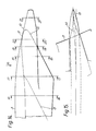
- Figure 4 is a side elevation on a further typical wing mounted pylon (Pylon A).
- Figure 5 is a half longitudinal cross-section through the pylon taken along line '5-5' in Figure 4.
- Figures 6 and 7 graphically illustrate the wing lower surface pressures inboard and outboard of the pylon and the adverse effect of the pylon of Figure 4 relative to that of Figure 2.
- Figures 8 and 9 respectively show the lift loss and drag penalty associated with the pylon of Figure 4 at a typical high speed cruise condition for a long range civil aircraft.
- Figure 10 illustrates a side elevation on a typical wing mounted pylon installation incorporating the pylon extension fairing of the present invention.
- Figure 11 illustrates a typical longitudinal cross-section through the pylon arrangement taken along a line '11-11' in Figure 10.
- Figures 12 and 13 respectively illustrate graphically the beneficial effect on lift and drag as a consequence of the present invention.
- Figure 14 is a side elevation on a rearward portion of a typical pylon incorporating the pylon extension fairing of the present invention.
- Figure 15 is a plan view on the aircraft wing with installed pylon viewed in direction of Arrow 15 in Figure 14.
- Figures 16-21 inclusive illustrate typical cross-section at selected datum positions along the pylon arrangement of the present invention as indicated with appropriate section lines in Figure 14.
- Figure 1 shows a typical engine installation for an aircraft whereby the engine 1 is mounted upon a pylon structure 2 depending from a wing 3.
- Underwing mounted pylons may similarly be used for carrying weapons and fuel tanks for example.
- Figures 2-5 inclusive show two typical pylon shapes for underwing mounted engines. That of Figures 2 and 3 (Pylon B) is designed for minimum aerodynamic penalty. The features of this design are low maximum thickness 4, illustrated as half plan thickness, start of the afterbody blend 5 well forward towards the local Wing Leading Edge and low pylon trailing edge angle 6. However, this low thickness means that the pylon is unable to satisfy the structural design requirements in terms of providing stiffness as well as space for internal accessories.
- the pylon arrangement of Figures 4 and 5 (Pylon A) is designed to meet the structural requirements but results in an increase in maximum thickness 7, illustrated in Figure 5 as half-plan thickness, a further aft start of the afterbody blend 5 and high pylon trailing edge angle 9. These features, however, tend to produce an aerodynamic penalty in the form of local loss of wing lift.
- the wing lift loss is caused by the increase in velocity due to the increase in pylon maximum thickness and the aft position of the afterbody blend 5 adversely affecting the wing lower surface pressures.
- Figure 6 and 7 the graphical representation of the wing lower surface pressures at inboard and outboard sides of the pylon and clearly shows the adverse performance of pylon A relative to pylon B.
- Figures 8 and 9 respectively illustrate the lift loss and drag penalty associated with pylon A at a typically high speed cruise condition for a long range civil aircraft. For this example the penalty is of the order of 1.25% loss of high speed buffet C L and 1% cruise drag penalty.
- the increase in flow velocities due to the pylon thickness 7 and aft position of the afterbody blend 5 can be reduced by adding a pylon trailing edge extension fairing 10.
- the amount of velocity increase is controlled by maintaining as much as possible the maximum width 7 of the pylon to beyond the trailing edge 11 of the wing 3.
- the afterbody of the fairing is thereafter closed in a tapering afterbody portion 8 to form a trailing edge.
- FIGs 14-21 inclusive illustrate in more detail the trailing edge extension fairing 10, Figures 16-21 inclusive in particular illustrating the cross-sectional development of the fairing relative to the basic pylon.
- the fairing 10 may be constructed as an integral part of the pylon or as a bolt-on addition. In the latter configuration the theoretical rearwards extent of the basic pylon is indicated at 12 in chain-dotted line.
- the extension 10 is configured in plan to lie along and about a datum centre line 14, which is expedient to accommodate the trailing edge flaps, ailerons, trailing edge structure etc.
Landscapes
- Engineering & Computer Science (AREA)
- Aviation & Aerospace Engineering (AREA)
- Structures Of Non-Positive Displacement Pumps (AREA)
- Aerodynamic Tests, Hydrodynamic Tests, Wind Tunnels, And Water Tanks (AREA)
- Aiming, Guidance, Guns With A Light Source, Armor, Camouflage, And Targets (AREA)
- Tents Or Canopies (AREA)
Claims (5)
- Agencement de pylône monté sur aile pour avion comprenant une aile (3) présentant un bord d'attaque, un bord de fuite, une surface aérodynamique supérieure, une surface aérodynamique inférieure et un pylône (2) monté sur la surface aérodynamique inférieure et dépendant de celle-ci dans la direction du bas;
ledit pylône (2) ayant une portion antérieure qui s'étend vers l'avant du bord d'attaque de l'aile et une portion postérieure qui s'étend vers l'arrière jusqu'à pratiquement le bord de fuite local (11) de l'aile et une portion intermédiaire sensiblement parallèle d'épaisseur maximum (7) sur au moins une partie de sa longueur;
ladite portion parallèle se fondant vers l'avant dans un bord d'attaque à la courbure régulière vers l'arrière dans une partie arrière conique pour former un bord de fuite,
caractérisé en ce que ledit pylône (2) comprend en outre un carénage (10) de prolongement du bord de fuite du pylône, contigu à la surface aérodynamique inférieure de l'aile, étant un prolongement parallèle arrière de l'épaisseur maximum (7) du pylône, s'étendant à cette épaisseur vers l'arrière du bord de fuite de l'aile, se terminant alors dans une partie (8) du bord de fuite arrière conique;
l'agencement étant tel que le pylône (2) peut être maintenu à l'épaisseur désirée maximum (7) avec pratiquement aucune perte locale de la sustentation aérodynamique et une pénalité en matière de traînée sensiblement réduite à zéro. - Agencement de pylône selon la revendication 1, dans lequel le bord de fuite de la partie arrière conique du pylône dans la direction du bas et diagonalement vers l'avant et la ligne (5) de la portion se fondant entre la partie parallèle et la portion arrière conique du pylône se trouve sensiblement parallèle au bord de fuite.
- Agencement de pylône selon la revendication 1 ou la revendication 2, dans lequel la ligne du bord de fuite (12) de la partie arrière conique du pylône est produite à partir d'un point coïncident sensiblement avec le bord de fuite local (11) de l'aile (3).
- Agencement de pylône selon la revendication 1, dans lequel le pylône comprend un carénage (10) de prolongement du bord de fuite formé intégralement.
- Agencement de pylône selon la revendication 1, dans lequel le carénage (10) de prolongement du bord de fuite est une addition boulonnée à la partie arrière conique et s'étend vers l'avant pour fournir sensiblement la continuité de la surface avec la partie parallèle du pylône.
Applications Claiming Priority (2)
| Application Number | Priority Date | Filing Date | Title |
|---|---|---|---|
| GB898928038A GB8928038D0 (en) | 1989-12-12 | 1989-12-12 | Aircraft wing pylon extensions for minimised aerodymanic penalties |
| GB8928038 | 1989-12-12 |
Publications (2)
| Publication Number | Publication Date |
|---|---|
| EP0432972A1 EP0432972A1 (fr) | 1991-06-19 |
| EP0432972B1 true EP0432972B1 (fr) | 1993-06-23 |
Family
ID=10667809
Family Applications (1)
| Application Number | Title | Priority Date | Filing Date |
|---|---|---|---|
| EP90313338A Expired - Lifetime EP0432972B1 (fr) | 1989-12-12 | 1990-12-07 | Prolongement du mât de support moteur d'une aile d'avion pour réduire les pertes aérodynamiques |
Country Status (5)
| Country | Link |
|---|---|
| US (1) | US5102069A (fr) |
| EP (1) | EP0432972B1 (fr) |
| DE (1) | DE69002053T2 (fr) |
| ES (1) | ES2042222T3 (fr) |
| GB (1) | GB8928038D0 (fr) |
Cited By (6)
| Publication number | Priority date | Publication date | Assignee | Title |
|---|---|---|---|---|
| EP0606514A1 (fr) * | 1993-01-15 | 1994-07-20 | Rolan Wu | Réseau d'antenne à décalage de phase avec élément en technique microbande |
| EP0995674A3 (fr) * | 1998-10-19 | 2001-03-28 | Honda Giken Kogyo Kabushiki Kaisha | Procédé pour la réduction de la résistance d'onde sur des avions |
| EP0995675A3 (fr) * | 1998-10-19 | 2001-03-28 | Honda Giken Kogyo Kabushiki Kaisha | Procédé por la réduction de la résistance d'onde sur des avions |
| US6308913B1 (en) | 1998-10-28 | 2001-10-30 | Honda Giken Kogyo Kabushiki Kaisha | Method for reducing wave resistance in airplane |
| US6378804B1 (en) | 1999-12-27 | 2002-04-30 | Aerospatiale Matra Airbus | Aircraft wing structure profiled suspension pylon |
| US6409123B2 (en) | 2000-04-10 | 2002-06-25 | Eads Airbus Sa | Aircraft wing structure profiled suspension pylon |
Families Citing this family (10)
| Publication number | Priority date | Publication date | Assignee | Title |
|---|---|---|---|---|
| US5810287A (en) * | 1996-05-24 | 1998-09-22 | The Boeing Company | Aircraft support pylon |
| GB0608983D0 (en) * | 2006-05-06 | 2006-06-14 | Rolls Royce Plc | Aeroengine mount |
| RU2312791C1 (ru) * | 2006-10-30 | 2007-12-20 | Закрытое акционерное общество "Гражданские самолеты Сухого" | Крыло летательного аппарата и подкрыльевой пилон |
| FR2922520B1 (fr) * | 2007-10-22 | 2010-04-23 | Airbus France | Procede de reduction de la trainee de compressibilite d'une voilure et conteneur mettant en oeuvre ce procede |
| FR2952349B1 (fr) * | 2009-11-06 | 2012-02-17 | Airbus Operations Sas | Procede de fabrication d'un mat reacteur equipe d'un generateur de tourbillons |
| GB201011056D0 (en) * | 2010-07-01 | 2010-08-18 | Rolls Royce Plc | Pylon for attaching a gas turbine engine |
| FR2979613B1 (fr) * | 2011-09-01 | 2014-06-13 | Snecma | Ensemble forme par un turbomoteur et son systeme d'attache a une structure d'aeronef |
| JP6266775B2 (ja) | 2013-07-26 | 2018-01-24 | エムアールエイ・システムズ・エルエルシー | 航空機エンジンパイロン |
| US9908631B2 (en) * | 2015-11-30 | 2018-03-06 | Embraer S.A. | Optimized aircraft pylon fairing |
| US20240239504A1 (en) * | 2023-01-17 | 2024-07-18 | General Electric Company | Open rotor pylon fairing |
Family Cites Families (7)
| Publication number | Priority date | Publication date | Assignee | Title |
|---|---|---|---|---|
| FR1545957A (fr) * | 1966-12-30 | 1968-11-15 | Rolls Royce | Dispositif de montage d'un moteur d'avion |
| US4067518A (en) * | 1976-05-20 | 1978-01-10 | Lockheed Corporation | Drag reducer for lift surface of aircraft |
| US4314681A (en) * | 1979-08-31 | 1982-02-09 | General Electric Company | Drag-reducing component |
| FR2555960B1 (fr) * | 1983-12-06 | 1986-09-19 | Aerospatiale | Aile d'aeronef en fleche pourvue d'un systeme hypersustentateur et d'un mat de suspension de moteur, ainsi que mat de suspension de moteur pour une telle aile |
| US4712750A (en) * | 1986-05-02 | 1987-12-15 | The Boeing Company | Temperature control device for jet engine nacelle associated structure |
| US4801058A (en) * | 1987-02-05 | 1989-01-31 | Rolls-Royce Plc | Aircraft and powerplant combinations |
| US4867394A (en) * | 1988-06-23 | 1989-09-19 | The United States Of America As Represented By The Administrator Of The National Aeronautics And Space Administration | Compression pylon |
-
1989
- 1989-12-12 GB GB898928038A patent/GB8928038D0/en active Pending
-
1990
- 1990-12-07 ES ES199090313338T patent/ES2042222T3/es not_active Expired - Lifetime
- 1990-12-07 EP EP90313338A patent/EP0432972B1/fr not_active Expired - Lifetime
- 1990-12-07 DE DE90313338T patent/DE69002053T2/de not_active Expired - Fee Related
- 1990-12-12 US US07/626,049 patent/US5102069A/en not_active Expired - Fee Related
Cited By (6)
| Publication number | Priority date | Publication date | Assignee | Title |
|---|---|---|---|---|
| EP0606514A1 (fr) * | 1993-01-15 | 1994-07-20 | Rolan Wu | Réseau d'antenne à décalage de phase avec élément en technique microbande |
| EP0995674A3 (fr) * | 1998-10-19 | 2001-03-28 | Honda Giken Kogyo Kabushiki Kaisha | Procédé pour la réduction de la résistance d'onde sur des avions |
| EP0995675A3 (fr) * | 1998-10-19 | 2001-03-28 | Honda Giken Kogyo Kabushiki Kaisha | Procédé por la réduction de la résistance d'onde sur des avions |
| US6308913B1 (en) | 1998-10-28 | 2001-10-30 | Honda Giken Kogyo Kabushiki Kaisha | Method for reducing wave resistance in airplane |
| US6378804B1 (en) | 1999-12-27 | 2002-04-30 | Aerospatiale Matra Airbus | Aircraft wing structure profiled suspension pylon |
| US6409123B2 (en) | 2000-04-10 | 2002-06-25 | Eads Airbus Sa | Aircraft wing structure profiled suspension pylon |
Also Published As
| Publication number | Publication date |
|---|---|
| GB8928038D0 (en) | 1990-02-14 |
| ES2042222T3 (es) | 1993-12-01 |
| US5102069A (en) | 1992-04-07 |
| DE69002053D1 (de) | 1993-07-29 |
| DE69002053T2 (de) | 1993-09-30 |
| EP0432972A1 (fr) | 1991-06-19 |
Similar Documents
| Publication | Publication Date | Title |
|---|---|---|
| EP0432972B1 (fr) | Prolongement du mât de support moteur d'une aile d'avion pour réduire les pertes aérodynamiques | |
| US5518204A (en) | High-efficiency, supersonic aircraft | |
| US3960345A (en) | Means to reduce and/or eliminate vortices, caused by wing body combinations | |
| EP0084686B1 (fr) | Avion | |
| EP0735970B1 (fr) | Ensemble aile/nacelle d'avion | |
| US20110180660A1 (en) | Aircraft having a lambda-box wing configuration | |
| EP4223633A1 (fr) | Systèmes d'ailette pour aéronef | |
| EP0222421A1 (fr) | Profil aérodynamique à circulation laminaire | |
| US5490644A (en) | Ducted boundary layer diverter | |
| CN1525920A (zh) | 一体化和/或模块化高速飞行器 | |
| US2927749A (en) | Airfoil wing root fillet | |
| GB2144688A (en) | Underwing engine installation for aircraft | |
| GB2547020A (en) | Design relating to improving aircraft | |
| US4629147A (en) | Over-the-wing propeller | |
| US6308913B1 (en) | Method for reducing wave resistance in airplane | |
| US5692704A (en) | Body tail unit for a commercial aircraft | |
| US6102328A (en) | Method for reducing wave resistance in airplane | |
| EP3626609A1 (fr) | Dispositif d'extrémité d'aile | |
| US5342004A (en) | Airfoil trailing flap | |
| EP4186790A1 (fr) | Porte de travée de train d'atterrissage d'aéronef | |
| US9908631B2 (en) | Optimized aircraft pylon fairing | |
| US4478377A (en) | Aircraft | |
| EP0995674B1 (fr) | Procédé pour la réduction de la résistance d'onde sur des avions | |
| Lee | The case for the tailless aircraft | |
| Dollyhigh | Development and analysis of a STOL supersonic cruise fighter concept |
Legal Events
| Date | Code | Title | Description |
|---|---|---|---|
| PUAI | Public reference made under article 153(3) epc to a published international application that has entered the european phase |
Free format text: ORIGINAL CODE: 0009012 |
|
| 17P | Request for examination filed |
Effective date: 19901217 |
|
| AK | Designated contracting states |
Kind code of ref document: A1 Designated state(s): BE DE ES FR GB IT NL SE |
|
| RAP3 | Party data changed (applicant data changed or rights of an application transferred) |
Owner name: BRITISH AEROSPACE PLC |
|
| 17Q | First examination report despatched |
Effective date: 19921123 |
|
| ITF | It: translation for a ep patent filed | ||
| GRAA | (expected) grant |
Free format text: ORIGINAL CODE: 0009210 |
|
| AK | Designated contracting states |
Kind code of ref document: B1 Designated state(s): BE DE ES FR GB IT NL SE |
|
| REF | Corresponds to: |
Ref document number: 69002053 Country of ref document: DE Date of ref document: 19930729 |
|
| ET | Fr: translation filed | ||
| REG | Reference to a national code |
Ref country code: ES Ref legal event code: FG2A Ref document number: 2042222 Country of ref document: ES Kind code of ref document: T3 |
|
| PLBE | No opposition filed within time limit |
Free format text: ORIGINAL CODE: 0009261 |
|
| STAA | Information on the status of an ep patent application or granted ep patent |
Free format text: STATUS: NO OPPOSITION FILED WITHIN TIME LIMIT |
|
| 26N | No opposition filed | ||
| EAL | Se: european patent in force in sweden |
Ref document number: 90313338.7 |
|
| NLT1 | Nl: modifications of names registered in virtue of documents presented to the patent office pursuant to art. 16 a, paragraph 1 |
Owner name: BAE SYSTEMS PLC |
|
| REG | Reference to a national code |
Ref country code: GB Ref legal event code: IF02 |
|
| PGFP | Annual fee paid to national office [announced via postgrant information from national office to epo] |
Ref country code: FR Payment date: 20031110 Year of fee payment: 14 |
|
| PGFP | Annual fee paid to national office [announced via postgrant information from national office to epo] |
Ref country code: NL Payment date: 20031117 Year of fee payment: 14 |
|
| PGFP | Annual fee paid to national office [announced via postgrant information from national office to epo] |
Ref country code: SE Payment date: 20031118 Year of fee payment: 14 Ref country code: GB Payment date: 20031118 Year of fee payment: 14 |
|
| PGFP | Annual fee paid to national office [announced via postgrant information from national office to epo] |
Ref country code: DE Payment date: 20031125 Year of fee payment: 14 |
|
| PGFP | Annual fee paid to national office [announced via postgrant information from national office to epo] |
Ref country code: ES Payment date: 20031205 Year of fee payment: 14 |
|
| PGFP | Annual fee paid to national office [announced via postgrant information from national office to epo] |
Ref country code: BE Payment date: 20031217 Year of fee payment: 14 |
|
| PG25 | Lapsed in a contracting state [announced via postgrant information from national office to epo] |
Ref country code: GB Free format text: LAPSE BECAUSE OF NON-PAYMENT OF DUE FEES Effective date: 20041207 |
|
| PG25 | Lapsed in a contracting state [announced via postgrant information from national office to epo] |
Ref country code: SE Free format text: LAPSE BECAUSE OF NON-PAYMENT OF DUE FEES Effective date: 20041208 |
|
| PG25 | Lapsed in a contracting state [announced via postgrant information from national office to epo] |
Ref country code: ES Free format text: LAPSE BECAUSE OF NON-PAYMENT OF DUE FEES Effective date: 20041209 |
|
| PG25 | Lapsed in a contracting state [announced via postgrant information from national office to epo] |
Ref country code: BE Free format text: LAPSE BECAUSE OF NON-PAYMENT OF DUE FEES Effective date: 20041231 |
|
| BERE | Be: lapsed |
Owner name: *BAE SYSTEMS P.L.C. Effective date: 20041231 |
|
| PG25 | Lapsed in a contracting state [announced via postgrant information from national office to epo] |
Ref country code: NL Free format text: LAPSE BECAUSE OF NON-PAYMENT OF DUE FEES Effective date: 20050701 Ref country code: DE Free format text: LAPSE BECAUSE OF NON-PAYMENT OF DUE FEES Effective date: 20050701 |
|
| GBPC | Gb: european patent ceased through non-payment of renewal fee |
Effective date: 20041207 |
|
| EUG | Se: european patent has lapsed | ||
| PG25 | Lapsed in a contracting state [announced via postgrant information from national office to epo] |
Ref country code: FR Free format text: LAPSE BECAUSE OF NON-PAYMENT OF DUE FEES Effective date: 20050831 |
|
| NLV4 | Nl: lapsed or anulled due to non-payment of the annual fee |
Effective date: 20050701 |
|
| REG | Reference to a national code |
Ref country code: FR Ref legal event code: ST |
|
| PG25 | Lapsed in a contracting state [announced via postgrant information from national office to epo] |
Ref country code: IT Free format text: LAPSE BECAUSE OF NON-PAYMENT OF DUE FEES Effective date: 20051207 |
|
| REG | Reference to a national code |
Ref country code: ES Ref legal event code: FD2A Effective date: 20041209 |
|
| BERE | Be: lapsed |
Owner name: *BAE SYSTEMS P.L.C. Effective date: 20041231 |