EP0433057B1 - Bandkassette mit Frontfläche zur Führung des daran anliegenden Bandes - Google Patents
Bandkassette mit Frontfläche zur Führung des daran anliegenden Bandes Download PDFInfo
- Publication number
- EP0433057B1 EP0433057B1 EP90313547A EP90313547A EP0433057B1 EP 0433057 B1 EP0433057 B1 EP 0433057B1 EP 90313547 A EP90313547 A EP 90313547A EP 90313547 A EP90313547 A EP 90313547A EP 0433057 B1 EP0433057 B1 EP 0433057B1
- Authority
- EP
- European Patent Office
- Prior art keywords
- tape
- cassette
- seam
- lower parts
- magnetic tape
- Prior art date
- Legal status (The legal status is an assumption and is not a legal conclusion. Google has not performed a legal analysis and makes no representation as to the accuracy of the status listed.)
- Expired - Lifetime
Links
Images


Classifications
-
- G—PHYSICS
- G11—INFORMATION STORAGE
- G11B—INFORMATION STORAGE BASED ON RELATIVE MOVEMENT BETWEEN RECORD CARRIER AND TRANSDUCER
- G11B23/00—Record carriers not specific to the method of recording or reproducing; Accessories, e.g. containers, specially adapted for co-operation with the recording or reproducing apparatus ; Intermediate mediums; Apparatus or processes specially adapted for their manufacture
- G11B23/02—Containers; Storing means both adapted to cooperate with the recording or reproducing means
- G11B23/023—Containers for magazines or cassettes
-
- G—PHYSICS
- G11—INFORMATION STORAGE
- G11B—INFORMATION STORAGE BASED ON RELATIVE MOVEMENT BETWEEN RECORD CARRIER AND TRANSDUCER
- G11B23/00—Record carriers not specific to the method of recording or reproducing; Accessories, e.g. containers, specially adapted for co-operation with the recording or reproducing apparatus ; Intermediate mediums; Apparatus or processes specially adapted for their manufacture
- G11B23/02—Containers; Storing means both adapted to cooperate with the recording or reproducing means
- G11B23/04—Magazines; Cassettes for webs or filaments
- G11B23/08—Magazines; Cassettes for webs or filaments for housing webs or filaments having two distinct ends
- G11B23/087—Magazines; Cassettes for webs or filaments for housing webs or filaments having two distinct ends using two different reels or cores
- G11B23/08707—Details
- G11B23/08785—Envelopes
-
- G—PHYSICS
- G11—INFORMATION STORAGE
- G11B—INFORMATION STORAGE BASED ON RELATIVE MOVEMENT BETWEEN RECORD CARRIER AND TRANSDUCER
- G11B23/00—Record carriers not specific to the method of recording or reproducing; Accessories, e.g. containers, specially adapted for co-operation with the recording or reproducing apparatus ; Intermediate mediums; Apparatus or processes specially adapted for their manufacture
- G11B23/02—Containers; Storing means both adapted to cooperate with the recording or reproducing means
- G11B23/04—Magazines; Cassettes for webs or filaments
- G11B23/08—Magazines; Cassettes for webs or filaments for housing webs or filaments having two distinct ends
- G11B23/087—Magazines; Cassettes for webs or filaments for housing webs or filaments having two distinct ends using two different reels or cores
- G11B23/08707—Details
- G11B23/08757—Guiding means
Definitions
- the present invention generally relates to tape cassettes and, more particularly, to a tape cassette in which a pair of tape reels are accommodated within a cassette casing and a magnetic tape is attached at respective ends to the reels and is wrapped about one or both of them.
- Such tape cassettes are now widely available as a record medium for a video tape recorder (VTR) and are described in Japanese Utility Model Laid-Open Gazette Number 63-153383.
- VTR video tape recorder
- a loop of the magnetic tape accommodated within the cassette casing is pulled out and wrapped around a rotary head drum.
- a rotary head obliquely scans this magnetic tape to perform a predetermined recording and/or reproduction on or from the tape.
- a magnetic tape is withdrawn into the cassette casing and the magnetic tape is transported in such a manner as to reduce the resistance exerted upon the magnetic tape.
- the magnetic tape is transported at high speed in the forward direction or in the reverse direction along a guide surface formed on the outer surfaces of the front side wall portions of the cassette casing. Accordingly, it is frequently observed that, when the magnetic tape is slidably transported along the guide surface of the cassette casing, the production of static electricity causes the magnetic tape to be stuck to the guide surface of the cassette casing.
- this type of tape cassette has the disadvantage that, if very small concave and convex portions are formed over the entire surface of the guide surface, when the upper and lower shells or parts forming the cassette casing are removed from metal moulds after the moulding-process, the resistance in the removal process increases considerably, thus making it impossible to remove the moulded products from the metal moulds.
- a tape cassette comprising a cassette casing with a front surface side and made up of an upper part and a lower part which are bonded together along a seam, and in which a pair of tape reels are aligned, and a magnetic tape wrapped around the pair of tape reels and attached at each end to respective ones of the tape reels, the magnetic tape and the tape reels being accommodated in the cassette casing, the tape cassette further comprising; a cassette lid attached to the front surface side of the cassette casing so as to be openable and closable; a guide surface formed on the front surface side of the cassette casing so as to oppose the inside of the cassette lid, a run of the magnetic tape extending along the guide surface; and a coarse surface area is formed on the guide surface, in which the coarse surface area is gradually reduced in width toward the seam between the upper and lower parts.
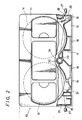
- this tape cassette has a cassette casing 10 which is shaped substantially as a flat rectangular solid.
- the cassette casing 10 is comprised of a pair of upper and lower shells or parts 11 and 12, respectively.
- the upper and lower parts 11 and 12 are moulded by a synthetic resin moulding-process and fastened together by some suitable means such as a bonding-process or the like.
- a pair of left and right tape reels 13 and 14, respectively, are accommodated within the cassette casing 10 in alignment with each other.
- a magnetic tape 15 is wrapped around the pair of tape reels 13 and 14 with each end of the tape being attached to a different one of the tape reels 13 and 14. In operation, the magnetic tape 15 is pulled out to the front wall side of the cassette casing 10 through opening portions 16 formed at the left and right sides of the front wall of the cassette casing 10 and extended along guide surfaces 18 formed on the surface of a front side wall portion 17.
- An openable and closable front lid 21 is provided at the front side of the front side wall portion 17 having the guide surfaces 18 along which the magnetic tape 15 is extended.
- a circular opening portion 22 is formed through the bottom portion of the cassette casing 10, and a cylindrical-shaped guide portion 23 is elongated within the cassette casing 10 so as to communicate with the circular opening portion 22.
- a lamp 24 is relatively inserted into the cylindrical-shaped guide portion 23 as shown in Fig. 2.
- a small aperture 26 in each side wall 5 of the cassette casing 10 allows separate light receiving elements 27 provided outside of each of the small apertures 26 to sense the tape ends in a manner known per se to those skilled in the art.
- a plurality of triangular coarse surface areas 30 are formed on the guide surfaces 18.
- Each coarse surface area 30 is shaped as a triangle such that its triangular area is gradually reduced toward the seam 19 where the upper and lower parts 11 and 12 are bonded together.
- the magnetic tape 15 is transported along the guide surface 18 having the coarse surfaces 30 as shown in Fig. 4.
- the coarse surface 30 corresponds to the surface of the metal mold from which the upper and lower parts 11 and 12 are molded and which is obtained by forming concave and convex portions on the surface of the metal mold by treatment with chemicals. That is, when the upper and lower parts 11 and 12 are formed on the corresponding surfaces by metal molds having concave and convex portions, the coarse surfaces 30 are formed.
- the guide surface 18 on which the coarse surface 30 is formed is formed as a gently inclined surface and its depth becomes largest at the seam 19 of the upper and lower parts 11 and 12.
- the cassette lid 21 is opened as shown in Fig. 1, whereby the magnetic tape 15 extended over the guide surfaces 18 of the front side wall portion 17 is exposed to the outside.
- This magnetic tape 15 is pulled out by a tape pulling pin (not shown) of the video tape recorder and is wrapped around the rotary head drum (not shown) of the video tape recorder in a manner known per se to those skilled in the art.
- the magnetic head mounted on the rotary head drum is rotated at high speed and the magnetic tape 15 is urged against a capstan by a pinch roller (not shown) and transported at constant speed, thus the predetermined recording and/or reproduction being performed. That is, in the recording mode or in the reproduction mode, the magnetic tape 15 is pulled out from the cassette casing and wound around the head drum of the video tape recorder.
- the magnetic tape 15 is transported directly along the guide surfaces 18 of the front side wall portion 17.
- the reason for this is to reduce the resistance applied to the magnetic tape 15 in order to move the magnetic tape 15 at high speed.
- the magnetic tape 15 is supplied from one tape reel, transported along the guide surfaces 18 of the front side wall portion 17, and is rewound by the other tape reel at high speed.
- the tape ends are fixed to the tape reels 13 and 14 via transparent leader tapes so that, when the magnetic tape 15 is thoroughly rewound by the other tape reel, the light from the lamp 24 is sensed by one of the light receiving elements 27 by way of the transparent leader tape, thereby detecting the tape end.
- the driving of the tape reels 13 and 14 is stopped simultaneously in a manner known per se by those skilled in the art.
- the guide surfaces 18 are flat, electrostatic charging tend to occur in the magnetic tape 15 or in the upper and lower parts 11 and 12. There is then the substantial possibility that the magnetic tape 15 will stick to the guide surfaces 18.
- the triangular coarse surface areas 30 are formed on the guide surfaces 18 of the upper and lower parts 11 and 12, and the points of the triangular coarse surface areas 30 are brought in contact with each other at the seam 19 of the upper and lower parts 11 and 12.
- the guide surfaces 18 of the front side wall portion 17 are gently inclined inwardly toward the seam 19 of the upper and lower parts 11 and 12 shown in Fig. 2, and the triangular coarse surface areas 30 are successively formed on the guide surface portions 18. Therefore, according to the thus arranged guide surface, electrostatic charging of the magnetic tape 15 or the upper and lower parts 11 and 12 is reduced, 20 and the magnetic tape 15 is prevented from being stuck to the guide surfaces 18.
- the coarse surface areas 30 are gradually reduced in width toward the seam 19 of the upper and lower parts 11 and 12, it becomes possible to considerably reduce the resistance of the guide surfaces 18 when the upper and lower parts 11 and 12 are removed from the metal molds as compared with the case in which the entire surface is made coarse. Accordingly, it is possible to obtain a tape cassette in which the magnetic tape 15 can be prevented from being stuck to the guide surfaces 18 and also the upper and lower parts 11 and 12 can be easily removed from the metal molds.
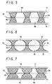
- the shape of the coarse surface area 30 formed on the guide surface 18 of the front side wall portion 17 is not limited to that of Fig. 3 and may be a trapezoidal-shape as shown in Fig. 5. Also in this case, the width of the trapezoidal-shaped coarse surface area is reduced toward the seam 19 of the upper and lower parts 11 and 12. Further, two sides of a triangular shape may be curved in an arc-fashion as shown in Fig. 6. Furthermore, as shown in Fig. 7, the coarse surface areas 30 may be shaped substantially as semicircles and their upper and lower semicircular portions may be contacted to each other at the seam 19 of the upper and lower parts 11 and 12.
- the coarse surface areas are formed on the guide surfaces of the front side of the cassette casing and which are inside of the cassette lid, and each of the coarse surface areas is gradually reduced in width near the seam 19 of the upper and lower parts. Therefore, according to the coarse surface areas, it becomes possible to effectively prevent electrostatic charging from occurring in the magnetic tape or in the upper and lower parts when the magnetic tape is slidably transported along the guide surfaces of the upper and lower parts. In addition, since the width of each of the coarse surface areas is gradually reduced near the seam 19 of the upper and lower parts, increased resistance of the coarsened guide surfaces when the upper and lower parts are removed from the metal molds can be avoided.
Landscapes
- Packaging Of Annular Or Rod-Shaped Articles, Wearing Apparel, Cassettes, Or The Like (AREA)
- Magnetic Record Carriers (AREA)
Claims (6)
- Bandkassette mit einem Kassettengehäuse (10) mit einer vorderen Oberflächenseite, die aus einem oberen Teil (11) und einem unteren Teil (12) besteht, die entlang eines Saums (19) miteinander verbunden sind, und in welcher zwei Bandspulen ausgerichtet sind, und einem Magnetband (15), das um die beiden Bandspulen (13, 14) geschlungen und an jedem Ende an der entsprechenden Bandspule (13, 14) befestigt ist, wobei das Magnetband (15) und die Bandspulen (13, 14) im Kassettengehäuse (10) untergebracht sind, wobei die Bandkassette außerdem aufweist:eine Kassettenklappe (21), die an der vorderen Oberflächenseite (17) des Kassettengehäuses (10) derart befestigt ist, daß diese geöffnet oder geschlossen werden kann;eine Führungsoberfläche (18), die auf der vorderen Oberflächenseite (17) des Kassettengehäuses (10) derart gebildet ist, daß sie der Innenseite der Kassettenklappe (21) gegenüberliegt, wobei eine Bahn eines Magnetbandes (15) sich entlang der Führungsoberfläche (18) erstreckt und ein rauher Oberflächenbereich (30) auf der Führungsoberfläche (17) gebildet ist;gekennzeichnet dadurch, daß der rauhe Oberflächenbereich (30) sich allmählich bezüglich seiner Breite in Richtung auf den Saum (19) zwischen dem oberen und unteren Teil (11, 12) verringert.
- Bandkassette nach Anspruch 1, bei der die Führungsoberfläche (18) so geneigt ist, daß sie am Saum (19) des oberen und unteren Teils (11, 12) tiefer ist.
- Bandkassette nach Anspruch 1, bei der der rauhe Oberflächenbereich (30) als zumindest ein Flächenbereich gebildet ist, der sich allmählich bezüglich seiner Breite in Richtung auf den Saum (19) des oberen und unteren Teils (11, 12) verringert.
- Bandkassette nach Anspruch 1 oder 2, bei der zumindest ein Flächenbereich eine zumindest annähernd dreiecksförmige Form aufweist, die sich allmählich bezüglich ihrer Breite in Richtung auf den Saum (19) des oberen und unteren Teils (11, 12) verringert.
- Bandkassette nach Anspruch 4, bei der zwei Seiten jedes dreieckigen rauhen Oberflächenbereichs bogenförmig ausgebildet sind.
- Bandkassette nach Anspruch 3, bei der mehrere Flächenbereiche vorhanden sind, die als Halbkreise ausgebildet sind, die miteinander am Saum (19) in Kontakt sind.
Applications Claiming Priority (2)
| Application Number | Priority Date | Filing Date | Title |
|---|---|---|---|
| JP324999/89 | 1989-12-15 | ||
| JP1324999A JP2734703B2 (ja) | 1989-12-15 | 1989-12-15 | テープカセット |
Publications (2)
| Publication Number | Publication Date |
|---|---|
| EP0433057A1 EP0433057A1 (de) | 1991-06-19 |
| EP0433057B1 true EP0433057B1 (de) | 1996-02-21 |
Family
ID=18172005
Family Applications (1)
| Application Number | Title | Priority Date | Filing Date |
|---|---|---|---|
| EP90313547A Expired - Lifetime EP0433057B1 (de) | 1989-12-15 | 1990-12-13 | Bandkassette mit Frontfläche zur Führung des daran anliegenden Bandes |
Country Status (6)
| Country | Link |
|---|---|
| US (1) | US5153800A (de) |
| EP (1) | EP0433057B1 (de) |
| JP (1) | JP2734703B2 (de) |
| KR (1) | KR910013211A (de) |
| DE (1) | DE69025460T2 (de) |
| SG (1) | SG49893A1 (de) |
Families Citing this family (2)
| Publication number | Priority date | Publication date | Assignee | Title |
|---|---|---|---|---|
| JP3739579B2 (ja) * | 1998-11-20 | 2006-01-25 | 富士写真フイルム株式会社 | 磁気テープカートリッジ |
| JP4366010B2 (ja) * | 2000-12-20 | 2009-11-18 | 日立オムロンターミナルソリューションズ株式会社 | 紙幣収納放出装置及び紙幣取扱装置 |
Family Cites Families (5)
| Publication number | Priority date | Publication date | Assignee | Title |
|---|---|---|---|---|
| JPS60159579U (ja) * | 1984-03-30 | 1985-10-23 | 富士写真フイルム株式会社 | 磁気テ−プカセツト |
| US4754357A (en) * | 1985-02-04 | 1988-06-28 | Minnesota Mining And Manufacturing Company | Static inhibiting bars for videotape cassette |
| JPH0454628Y2 (de) * | 1985-06-03 | 1992-12-22 | ||
| US4884159A (en) * | 1986-11-05 | 1989-11-28 | Tdk Corporation | Braking arrangement in a magnetic tape cassette |
| JP2540889B2 (ja) * | 1987-11-20 | 1996-10-09 | ソニー株式会社 | テ―プカセット |
-
1989
- 1989-12-15 JP JP1324999A patent/JP2734703B2/ja not_active Expired - Fee Related
-
1990
- 1990-12-11 US US07/625,554 patent/US5153800A/en not_active Expired - Fee Related
- 1990-12-13 EP EP90313547A patent/EP0433057B1/de not_active Expired - Lifetime
- 1990-12-13 DE DE69025460T patent/DE69025460T2/de not_active Expired - Fee Related
- 1990-12-13 SG SG1996008422A patent/SG49893A1/en unknown
- 1990-12-14 KR KR1019900020578A patent/KR910013211A/ko not_active Ceased
Also Published As
| Publication number | Publication date |
|---|---|
| JP2734703B2 (ja) | 1998-04-02 |
| DE69025460D1 (de) | 1996-03-28 |
| DE69025460T2 (de) | 1996-07-11 |
| SG49893A1 (en) | 1998-06-15 |
| EP0433057A1 (de) | 1991-06-19 |
| KR910013211A (ko) | 1991-08-08 |
| US5153800A (en) | 1992-10-06 |
| JPH03187082A (ja) | 1991-08-15 |
Similar Documents
| Publication | Publication Date | Title |
|---|---|---|
| FI73534C (fi) | Bandkassett. | |
| US3712559A (en) | Tape cassette and improvements therefor | |
| US4706149A (en) | Tape cassette | |
| CA1094036A (en) | Tape reel | |
| JP2685444B2 (ja) | 磁気テープカセツト | |
| US4257076A (en) | Grooved drum for tape recording and/or reproducing apparatus | |
| US4196873A (en) | Two tape-cartridge type magnetic-tape recording/reproducing apparatus | |
| EP0433057A1 (de) | Bandkassette mit Frontfläche zur Führung des daran anliegenden Bandes | |
| EP0308487B1 (de) | Führungsvorrichtung für ein schraubenförmig abgetastetes band | |
| EP0317297B1 (de) | Bandkassette | |
| US4779150A (en) | Pneumatically controlled tape-loading tape-transporting apparatus | |
| US5198951A (en) | Tape cassette with magnetic tape outlets openable and closable by lids | |
| US4462553A (en) | Endless cassette tape for video tape recorder | |
| EP0323101B1 (de) | Bandkassette mit Vorder- und Hinterklappe | |
| NL8202625A (nl) | Miniatuur soort bandcassette. | |
| KR100292731B1 (ko) | 테이프 카셋트 | |
| US4840326A (en) | Magnetic tape cassette | |
| US4514774A (en) | Method and an apparatus for extracting tape from a tape cartridge of the internal belt-drive type | |
| JP3492936B2 (ja) | テープカセット及びテープカセット用成形金型 | |
| US4813628A (en) | Slack limiter for a magnetic tape cassette | |
| US5523905A (en) | Recording or reproducing apparatus with tape guide members providing a space to receive a tape-end sensor | |
| JPS6260742B2 (de) | ||
| CN100489979C (zh) | 磁记录再生装置 | |
| JP3153916B2 (ja) | テーププレーヤ | |
| KR200141233Y1 (ko) | 자기기록재생기의 테이프말림 방지장치 |
Legal Events
| Date | Code | Title | Description |
|---|---|---|---|
| PUAI | Public reference made under article 153(3) epc to a published international application that has entered the european phase |
Free format text: ORIGINAL CODE: 0009012 |
|
| AK | Designated contracting states |
Kind code of ref document: A1 Designated state(s): DE FR GB |
|
| 17P | Request for examination filed |
Effective date: 19911125 |
|
| 17Q | First examination report despatched |
Effective date: 19940420 |
|
| GRAA | (expected) grant |
Free format text: ORIGINAL CODE: 0009210 |
|
| AK | Designated contracting states |
Kind code of ref document: B1 Designated state(s): DE FR GB |
|
| REF | Corresponds to: |
Ref document number: 69025460 Country of ref document: DE Date of ref document: 19960328 |
|
| ET | Fr: translation filed | ||
| PGFP | Annual fee paid to national office [announced via postgrant information from national office to epo] |
Ref country code: GB Payment date: 19961204 Year of fee payment: 7 |
|
| PGFP | Annual fee paid to national office [announced via postgrant information from national office to epo] |
Ref country code: FR Payment date: 19961211 Year of fee payment: 7 |
|
| PLBE | No opposition filed within time limit |
Free format text: ORIGINAL CODE: 0009261 |
|
| STAA | Information on the status of an ep patent application or granted ep patent |
Free format text: STATUS: NO OPPOSITION FILED WITHIN TIME LIMIT |
|
| 26N | No opposition filed | ||
| PG25 | Lapsed in a contracting state [announced via postgrant information from national office to epo] |
Ref country code: GB Free format text: LAPSE BECAUSE OF NON-PAYMENT OF DUE FEES Effective date: 19971213 |
|
| PG25 | Lapsed in a contracting state [announced via postgrant information from national office to epo] |
Ref country code: FR Free format text: THE PATENT HAS BEEN ANNULLED BY A DECISION OF A NATIONAL AUTHORITY Effective date: 19971231 |
|
| GBPC | Gb: european patent ceased through non-payment of renewal fee |
Effective date: 19971213 |
|
| REG | Reference to a national code |
Ref country code: FR Ref legal event code: ST |
|
| PGFP | Annual fee paid to national office [announced via postgrant information from national office to epo] |
Ref country code: DE Payment date: 20020109 Year of fee payment: 12 |
|
| PG25 | Lapsed in a contracting state [announced via postgrant information from national office to epo] |
Ref country code: DE Free format text: LAPSE BECAUSE OF NON-PAYMENT OF DUE FEES Effective date: 20030701 |