EP0433058A2 - Enrouleur à blocage en cas d'urgence pour ceinture de sécurité d'automobile - Google Patents
Enrouleur à blocage en cas d'urgence pour ceinture de sécurité d'automobile Download PDFInfo
- Publication number
- EP0433058A2 EP0433058A2 EP90313548A EP90313548A EP0433058A2 EP 0433058 A2 EP0433058 A2 EP 0433058A2 EP 90313548 A EP90313548 A EP 90313548A EP 90313548 A EP90313548 A EP 90313548A EP 0433058 A2 EP0433058 A2 EP 0433058A2
- Authority
- EP
- European Patent Office
- Prior art keywords
- webbing
- pivotable
- retractor
- belt spool
- rotatable member
- Prior art date
- Legal status (The legal status is an assumption and is not a legal conclusion. Google has not performed a legal analysis and makes no representation as to the accuracy of the status listed.)
- Withdrawn
Links
Images


Classifications
-
- B—PERFORMING OPERATIONS; TRANSPORTING
- B60—VEHICLES IN GENERAL
- B60R—VEHICLES, VEHICLE FITTINGS, OR VEHICLE PARTS, NOT OTHERWISE PROVIDED FOR
- B60R22/00—Safety belts or body harnesses in vehicles
- B60R22/34—Belt retractors, e.g. reels
- B60R22/36—Belt retractors, e.g. reels self-locking in an emergency
- B60R22/415—Belt retractors, e.g. reels self-locking in an emergency with additional means allowing a permanent locking of the retractor during the wearing of the belt
Definitions
- the present invention relates generally to an emergency locking retractor for an automotive seat belt arrangement. More specifically, the invention relates to an emergency locking retractor for an automotive seat belt arrangement which can not only be used for restricting a passenger on a vehicular seat, but can be also used for fixing a child seat to the vehicular seat.
- an emergency locking retractor for automotive seat belt arrangement is provided with a locking mechanism for preventing a belt from being drawn out when the vehicle receives shock.
- a locking mechanism includes a webbing sensor which operates when the belt is rapidly drawn out of the retractor, and a vehicle sensor which operates when the vehicle is rapidly accelerated or decelerated. When at least one of these sensors operates, the retractor prevents the belt from being drawn out. On the other hand, when these sensors does not operate, the belt is free to be drawn out of the retractor by the passenger, and to be rewound or retracted onto the retractor by means of a coil spring.
- the child seat When a child seat is fixed to the vehicle seat by means of such a seat belt arrangement, the child seat may move from its predetermined position on the vehicle seat due to the movement of a child in the child seat, so that the belt is drawn out of the retractor and loosens. Thus, the child seat may move from its intended fixed position relative the vehicle seat.
- the retractor can prevent the belt from being drawn out independently of operations of the webbing sensor and the vehicle sensor.
- the belt is prevented from being drawn out by means of the locking mechanism only when at least one of the sensors operates. In this way, in order to distinguish the usual use from the specific use for fixing the child seat to the vehicular seat, full length of the belt must be previously drawn out of the retractor when the seat belt arrangement is used for fixing the child seat to the vehicular seat.
- the aforementioned conventional emergency locking retractors must be provided with a specific gear mechanism for preventing the belt from being drawn out when it is used for fixing the child seat to the vehicular seat.
- a specific gear mechanism for preventing the belt from being drawn out when it is used for fixing the child seat to the vehicular seat.
- an emergency locking retractor for a vehicular seat belt arrangement comprising:
- an emergency locking retractor for an automotive seat belt arrangement includes a pivotable plate housed within a retractor housing and pivotably supported thereon, and a pivotable tooth member pivotably supported on the retractor housing.
- the pivotable plate is biased by means of a spring so that the free end thereof comes into contact with a webbing wound onto a belt spool.
- the pivotal tooth member is connected to the pivotable plate by means of a coil spring so that the pivotable tooth member pivots depending upon pivotal movement of the pivotable plate.
- the free end of the pivotable tooth member engages one of the teeth formed on the circumferential wall of a cam wheel which normally rotates with the belt spool in a drawn direction in which the webbing is drawn out of the retractor housing. While the child seat is fixed to the vehicular seat by means of the seat belt arrangement, the free end of the pivotable tooth member remains engaged in the one of the teeth independently of the operation of the webbing sensor on the vehicular sensor, so as to prevent the webbing from being drawn out of the retractor housing.
- Fig. 1 is an exploded, perspective view of the first preferred embodiment of an emergency locking retractor for an automotive seat belt arrangement, according to the present invention
- Fig. 2 is a perspective view of a cam wheel of the emergency locking retractor of Fig. 1, which shows the rear side of the cam wheel;
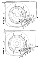
- Fig. 3 is a schematic view of the emergency locking retractor of Fig. 1, which is explanatory of the operation of the emergency locking retractor;
- Fig. 4 is an exploded, perspective view of the second preferred embodiment of an emergency locking retractor for an automotive seat belt arrangement, according to the present invention
- Fig. 5 is a schematic view of the emergency locking retractor of Fig. 4, which is explanatory of the operation of the emergency locking retractor;
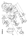
- Fig. 6 is an exploded, perspective view of the third preferred embodiment of an emergency locking retractor for an automotive seat belt arrangement, according to the present invention.
- Fig. 7 is a side elevation of a pivotable plate of the emergency locking retractor of Fig. 7;
- Fig. 8 is a plan view of the pivotable plate of Fig. 7;
- Figs. 9 through 11 are schematic views of the emergency locking retractor of Fig. 6, which are explanatory of the operation of the emergency locking retractor.
- FIG. 1 through 3 there is shown the first preferred embodiment of an emergency locking retractor for an automotive seat belt arrangement, according to the present invention.
- the emergency locking retractor includes a retractor housing 10 for receiving therein a belt spool 12 onto which a webbing 14 is wound as shown in Fig. 3.
- the retractor housing 10 has a pair of side walls 16 and 18 parallel to each other.
- the side walls 16 and 18 are respectively formed with circular through openings 16a and 18a on which the belt spool 12 is rotatably supported.
- the side wall 16 also has a plurality of latching teeth 16b which are arranged symmetrically around the edge of the circular through opening 16a and which project outward and substantially perpendicular to the plane of the side wall 16.
- the stationary latching case 20 is secured to the outer surface of the side wall 16 of the retractor housing 10.
- the stationary latching case 20 has a circular through opening 20a at the center thereof, and a plurality of slots 20b symmetrically around the circular through opening 20a.
- the stationary latching case 20 also has a plurality of mounting portions 20c which project radially from the outer periphery thereof.
- the stationary latching case 20 is mounted on the side wall 16 of the retractor housing 10 by fixing the mounting portions 20c to the side wall 16 by means of screws, the circular through opening 16a faces the circular through opening 20a, and the latching teeth 16b pass through the slots 20b.
- the stationary latching case 20 has a plurality of ratchet teeth 20d on the internal periphery thereof.
- a spring case 22 is secured to the outer surface of the side wall 18 of the retractor housing 10.
- the spring case 22 houses therein a spring (not shown) which engages one end of the belt spool 12 to bias the belt spool 12 in the retraction direction in which the webbing 14 is wound onto the belt spool 12.
- a locking disc 24 is secured to the other end portion of the belt spool 12 so as to rotate therewith, and is housed within the stationary latching case 20.
- a plurality of locking claws 24a project from the circumferential edge of the locking disc 24, and are arranged symmetrically in a radial direction of the locking disc 24.
- the locking claws 24a extend essentially perpendicular to the plane of the locking disc 24, but are oblique to the axis of the belt spool 12.
- An essentially disc-shaped leaf spring 26 is arranged on the outer surface of the locking disc 24 within a space defined by the locking claws 24a.
- the leaf spring 26 has resilient strips 26a which extend in an essentially circumferential and slightly oblique direction.
- the resilient strips 26a are adapted to bias a substantially annular locking wheel 28 in a direction away from the locking disc 24.
- the locking wheel 28 has outer locking teeth 28a which project radially outward from the outer periphery thereof, and inner locking teeth 28b which project radially inward from the inner periphery thereof.
- Each of adjacent pairs of the outer locking teeth 28a are arranged within a space defined between the adjacent locking claws 24a so as to be engageable with the locking claws 24a of the locking disc 24 and with the latching teeth 16b of the retractor housing 10.
- the locking wheel 28 is received in a cam wheel 30.
- the cam wheel 30 has an inner annular wall 30a which projects axially inwards.
- the inner annular wall 30a has four notches 30b which are engageable with the inner locking teeth 28b of the locking wheel 28 so that the cam wheel 30 normally rotates with the locking wheel 28.
- the cam wheel 30 also receives therein an inertia responsive flywheel 32 between the inner surface of the cam wheel 30 and the locking wheel 28.
- the flywheel 32 is made from an essentially ellipse metal, and has an essentially circular through opening 32a through which the inner annular wall 30a pass.
- the flywheel 32 is designed to be normally rotatable with the cam wheel 30 in accordance with rotation of the belt spool 12.
- the cam wheel 30 has a plurality of ratchet teeth 30c on the axial half of the outer periphery thereof.
- a recess 30d is formed on the other axial half of the outer periphery of the cam wheel 30, a recess 30d is formed.
- the recess 30d is formed with a cylindrical pivot 30e which projects axially.
- a webbing sensor pawl 34 is pivotably supported on the pivot 30e of the cam wheel 30, and is biased toward its unlocking position, in which essentially entire portion of the webbing sensor pawl 34 is received within the recess 30d, by means of a leaf spring 36.
- the webbing sensor pawl 34 has a projection 34a at the free end portion thereof.
- the projection 34a of the webbing sensor pawl 34 is designed to be in contact with the flywheel 32 through a through opening 30f formed in the recess 30d, by biasing force of the leaf spring 34b.
- a part of the flywheel 32 is designed to pass through the through opening 30f to cause the webbing sensor pawl 34 to move to a locking position in which the webbing sensor pawl 34 engages one of the ratchet teeth 20d of the stationary latching case 20, so as to prevent the cam wheel 30 from rotating relative to the stationary latching case 20.
- a vehicle sensor 35 is also mounted on the outer surface of the side wall 16 of the retractor housing 10 via a frame 36.
- the frame 36 has a through opening which essentially coincides with a through opening 16c formed in the side wall 16.
- the vehicle sensor 35 comprises a weight retainer 38, an inertia-sensitive weight 40 and a vehicle sensor pawl 42.
- the weight retainer 38 is fixed to the side wall 16 of the retractor housing 10 via the frame 36 by means of screws 44.
- the inertia-sensitive weight 40 is received within the weight retainer 38.
- the vehicle sensor pawl 42 is pivotably supported on the weight retainer 38, and is normally in contact with the upper surface of the inertia-sensitive weight 40.
- the inertia-sensitive weight 40 is designed to tilt in response to excessive inertial moments to displace the vehicle sensor pawl 40 upwards.
- the free end of the vehicle sensor pawl 42 passes through a through opening 20e formed in the circumferential wall of the stationary latching case 20 to engage one of the ratchet teeth 30c so as to prevent the cam wheel 30 from rotating relative to the stationary latching case 20.
- the locking mechanism in order that the locking mechanism can also prevent the belt from being drawn out of the retractor when the retractor is used for fixing a child seat to the vehicular seat, the locking mechanism cooperates with a locking assembly which prevents the cam wheel from rotating independently of the webbing sensor and the vehicle sensor.
- the locking assembly comprises a tooth 46, a pivotable plate 48, a pivotal shaft 50. a lever 52 and coil springs 54 and 56.
- the tooth 46 is pivotably supported on a cylindrical projection 16d which is projects from the outer surface of the side wall 16 of the retractor housing 10. The free end of the tooth 46 can pass through the through opening 20e to be engageable with the ratchet teeth 30c.
- Both ends of the pivotal shaft 50 is pivotably supported on the side walls 16 and 18 of the retractor housing 10.
- the pivotable plate 48 is housed within the retractor housing 10, and the base end portion thereof is fixed to the pivotal shaft 50 so that the pivotable plate 48 is pivotably supported on the side walls 16 and 18.
- the pivotable plate 48 is connected to one end of the spring 54, the other end of which is connected to the retractor housing 10, so as to be biased toward the belt spool 12 by means of the spring 54.
- the lever 52 is pivotably supported on one end of the pivotal shaft 50 which projects from the side wall 16.
- the other spring 56 is connected between projections 52a and 46a which project from the free ends of the lever 52 and the tooth 46. Referring to Fig.
- the line A-A which is drawn between the central points of the projection 46a of the tooth 46, the projection 16d of the side wall 16 and the pivotal shaft 50 when all the central points are in align with each other.
- This line A-A acts as a dead line of the locking mechanism.
- the full length of the webbing 14 is slowly drawn out of the retractor housing 10 so as not to cause the webbing sensor to operate.
- the pivotable plate 48 pivots toward the axis of the belt spool 12 since the pivotable plate 48 is biased against the webbing 14 wound onto the belt spool 12.
- the pivotal shaft 50 and the lever 52 pivot, so that the spring 56 exceeds the dead point (line A-A).
- the tooth 46 pivots to the right of the line A-A, so that the tooth 46 becomes to be engageable with one of the ratchet teeth 30c.
- a child seat is arranged on the vehicular seat, and then the belt is passed over the child seat or through a groove formed therein.
- extra length of the webbing 14 is rewound onto the belt spool 12 by the spring force of the coil spring.
- the tooth 46 can pass over the ratchet teeth 30c while it comes into contact with one of the ratchet teeth 30c.
- this engagement of the tooth 46 with the ratchet teeth 30c is designed to prevent the cam wheel 30 from rotating to prevent the belt spool 12 from rotating in the drawn direction in which the webbing 14 is drawn out of the retractor housing 10.
- the child seat is fixed to the vehicle seat.
- the tooth 46 can not disengage from the ratchet teeth 30c since a predetermined length of the webbing 14 is drawn out of the retractor housing 10. Therefore, even if the webbing sensor or the vehicle sensor operates when the seat belt arrangement is used for fixing the child seat to the vehicle seat, the retractor remains preventing the belt from being drawn out since the tooth 46 remains engaging one of the ratchet teeth 30c.
- the full length of the webbing 14 is not required to be drawn out. Therefore, since the belt spool 12 does not pivot until the tooth 46 comes into contact with the ratchet teeth 30c, the passenger can not only freely draw a desired length of webbing 14 out of the retractor housing 10, but the extra length of webbing 14 can be also retracted by means of the retractor. In this case, when the webbing 14 is rapidly drawn out of the retractor housing 10, the flywheel 32 can not follow rotation of the cam wheel 30, i.e.
- the flywheel 32 rotates reversely relative to rotation of the cam wheel 30, so that the flywheel 32 thrusts the webbing sensor pawl 34 against the spring force of the leaf spring 36 to cause the webbing sensor pawl 34 to protrude from the circumferential wall of the cam wheel 30.
- the webbing sensor pawl 34 engages one of the ratchet teeth 20d formed in the inner periphery of the latching case 20, so as to prevent the cam wheel 30 from rotating.
- the inertia-sensitive weight 40 tilts so that the vehicle sensor pawl 42 pivots to engage one of the ratchet teeth 30c to prevent the cam wheel 30 from rotating.
- tension is applied to the webbing 14 in the drawn direction due to inertial force of the passenger. Therefore, the belt spool 12, the locking disc 24 and the locking wheel 28 rotate in the drawn direction, so that the locking wheel 28 moves toward the retractor housing 10 against the spring force of the leaf spring 26 while the inner locking teeth 28b comes into contact with the notches 30b of the cam wheel 30.
- the base end portions of the outer locking teeth 20b engage the locking claws 24a of the locking disc 24, and the top end portion of the outer locking teeth 20b engage the latching teeth 16b of the retractor housing 10, so as to prevent the belt spool 12 from rotating in the drawn direction. In this way, the passenger can be restricted on the vehicular seat when the vehicle gets a shock.
- Figs. 4 and 5 show the second preferred embodiment of an emergency locking retractor, according to the present invention.
- This embodiment is similar to the first preferred embodiment except that the pivotable plate 48 is replaced by a pivotable plate 60. Length of the pivotable plate 60 is shorter than that of the pivotable plate 48 of the first preferred embodiment. As can be seen clearly from Fig. 5, the free end portion of the pivotable plate 60 is designed to engage one of grooves 12a which are formed in the belt spool 12 so as to extend parallel to the axis of the belt spool 12, when full length of the webbing 14 is drawn out of the retractor.
- the free end portion of the pivotable plate 60 disengages from the groove 12a due to rotation of the belt spool 12.
- the tooth 46 can pass over the ratchet teeth 30c while it comes into contact with one of the ratchet teeth 30c.
- this engagement of the tooth 46 with the ratchet teeth 30c is designed to prevent the cam wheel 30 from rotating to prevent the belt spool 12 from rotating in the drawn direction in which the webbing 14 is drawn out of the retractor housing 10. In this way, the child seat is fixed to the vehicle seat.
- pivotal angle of the pivotable plate 60 is greater than that of the pivotable plate 48 of the first preferred embodiment. Therefore, it is possible to surely cause the tooth 46 to engage the ratchet teeth 30c, even if the spring forces of the coil springs 54 and 56 become weak.
- Figs. 6 through 11 show the third preferred embodiment of an emergency locking retractor, according to the present invention.
- the locking assembly differs from that of the first preferred embodiment.
- the locking assembly generally comprises a tooth 70, a pivotable plate 72, a pivotal shaft 74, a lever 76, springs 78 and 80.
- the tooth 70 is arranged on the outer surface of the side wall 16 of the retractor housing 10 to be pivotably supported thereon by means of a screw 82.
- the free end of the tooth 70 can pass through a through opening 20f formed in the circumferential wall of the stationary latching case 20 at a location neighboring the through opening 20e, to be engageable with the ratchet teeth 30c.
- Both ends of the pivotal shaft 74 is pivotably supported on the side walls 16 and 18 of the retractor housing 10 via bearings 84.
- the pivotable plate 72 is housed within the retractor housing 10, and the base end portion thereof is fixed to the pivotal shaft 74 so that the pivotable plate 72 is pivotably supported on the side walls 16 and 18.
- One end of the spring 78 engages a groove 74a formed in one end portion of the pivotal shaft 74.
- the other end of the spring 78 is fixed to an engaging portion 16e formed in the side wall 16 of the retractor housing 10. so as to bias the pivotable plate 72 toward the belt spool 12.
- the free end portion of the pivotable plate 72 is designed to engage a groove 12c formed in the belt spool 12, when full length of the webbing 14 is drawn out of the retractor. As shown in Figs.
- the pivotable plate 72 has a first contact portion 72a which is arranged at a location slightly away from the free end portion of the pivotable plate 72 to come into contact with the webbing 14 wound onto the belt spool 12 when the diameter of the webbing 14 is relatively great, and a second contact portion 72b which is arranged at a location neighboring the free end portion of the pivotable plate 72 to come into contact with the webbing 14 wound onto the belt spool 12 when the diameter of the webbing 14 is relatively small.
- the lever 76 is pivotably supported on one end portion of the pivotal shaft 74 which projects from the side wall 16.
- the other spring 80 is connected between projecting pins 70a and 76a which project from the free ends of the tooth 70 and the lever 76.
- the free end portion of the pivotable plate 72 disengages from the groove 12b due to rotation of the belt spool 12.
- the tooth 70 can pass over the ratchet teeth 30c while it comes into contact with one of the ratchet teeth 30c.
- this engagement of the tooth 70 with the ratchet teeth 30c is designed to prevent the cam wheel 30 from rotating to prevent the belt spool 12 from rotating in the drawn direction in which the webbing 14 is drawn out of the retractor housing 10. In this way, the child seat is fixed to the vehicular seat.
- contacting portion of the pivotable plate 72 with the webbing 14 is changed from the first contact portion 72a to the second contact portion 72b while the diameter of the webbing 14 wound onto the belt spool 12 decreases, so that pivotal angle of the pivotable plate 72 is greater than that of the pivotable plate 48 of the first preferred embodiment. Therefore, it is possible to surely cause the tooth 70 to engage the ratchet teeth 30c, even if the spring forces of the springs 78 and 80 become weak.
- the dead point (the line A-A) is normally inclined counterclockwise relative to the vertical direction as shown in Fig. 9.
- the spring 80 moves to the right to exceed the dead point, so that the free end portion of the tooth 70 engages one of the ratchet teeth 30c of the cam wheel 30.
- the pivotable plate 72 further pivots until the free end portion of the pivotable plate 72 engages the groove 12b. In this way, the spring 80 can surely exceed the dead point, so that the free end portion of the pivotable plate 72 can surely engage the groove 12b.
- the direction of the dead point (the line A-A) is changed to a substantially vertical direction.
- the tooth 70 remains engaging the one of the ratchet teeth 30c so as to prevent the webbing 14 from being drawn out of the retractor housing 10. That is, by changing the position of the dead line when rewinding from that when drawing, there is a difference between the timings in that the tooth 70 engages with and disengages from the ratchet teeth 30c.
Landscapes
- Engineering & Computer Science (AREA)
- Mechanical Engineering (AREA)
- Automotive Seat Belt Assembly (AREA)
Applications Claiming Priority (4)
| Application Number | Priority Date | Filing Date | Title |
|---|---|---|---|
| JP144543/89U | 1989-12-15 | ||
| JP14454289U JPH0383155U (fr) | 1989-12-15 | 1989-12-15 | |
| JP144542/89U | 1989-12-15 | ||
| JP14454389U JPH0383156U (fr) | 1989-12-15 | 1989-12-15 |
Publications (2)
| Publication Number | Publication Date |
|---|---|
| EP0433058A2 true EP0433058A2 (fr) | 1991-06-19 |
| EP0433058A3 EP0433058A3 (en) | 1991-08-21 |
Family
ID=26475927
Family Applications (1)
| Application Number | Title | Priority Date | Filing Date |
|---|---|---|---|
| EP19900313548 Withdrawn EP0433058A3 (en) | 1989-12-15 | 1990-12-13 | Emergency locking retractor for automotive seat belt arrangement |
Country Status (1)
| Country | Link |
|---|---|
| EP (1) | EP0433058A3 (fr) |
Cited By (3)
| Publication number | Priority date | Publication date | Assignee | Title |
|---|---|---|---|---|
| GB2241636B (en) * | 1990-02-10 | 1993-11-10 | Autoflug Gmbh | Self-locking belt roller |
| EP0553458A3 (fr) * | 1992-01-31 | 1994-04-20 | Fuji Autolib Co Ltd | |
| CN111688628A (zh) * | 2020-07-16 | 2020-09-22 | 延锋汽车智能安全系统有限责任公司 | 线控调角卷收器的传动箱组件 |
Family Cites Families (3)
| Publication number | Priority date | Publication date | Assignee | Title |
|---|---|---|---|---|
| CA1221074A (fr) * | 1982-11-29 | 1987-04-28 | Takayuki Ando | Rappel de sangle |
| JPS59150461U (ja) * | 1983-03-30 | 1984-10-08 | 富士機工株式会社 | エマ−ジエンシイ・ロツキング・リトラクタ |
| US4552319A (en) * | 1983-12-14 | 1985-11-12 | Irvin Industries Inc. | Combination VSI and ALR retractor |
-
1990
- 1990-12-13 EP EP19900313548 patent/EP0433058A3/en not_active Withdrawn
Cited By (3)
| Publication number | Priority date | Publication date | Assignee | Title |
|---|---|---|---|---|
| GB2241636B (en) * | 1990-02-10 | 1993-11-10 | Autoflug Gmbh | Self-locking belt roller |
| EP0553458A3 (fr) * | 1992-01-31 | 1994-04-20 | Fuji Autolib Co Ltd | |
| CN111688628A (zh) * | 2020-07-16 | 2020-09-22 | 延锋汽车智能安全系统有限责任公司 | 线控调角卷收器的传动箱组件 |
Also Published As
| Publication number | Publication date |
|---|---|
| EP0433058A3 (en) | 1991-08-21 |
Similar Documents
| Publication | Publication Date | Title |
|---|---|---|
| US5882084A (en) | Tilt locking seat belt retractor | |
| US3819126A (en) | Seat belt retractor with gear wheel actuated locking means | |
| US4083512A (en) | Independent redundant clutchless retractor | |
| US4467981A (en) | Webbing retractor | |
| US10919489B2 (en) | Seatbelt retractor | |
| GB2026305A (en) | Safety belt apparatus | |
| US5022601A (en) | Locking mechanism for webbing retractor | |
| GB2026847A (en) | Safety belt apparatus | |
| US4485986A (en) | Emergency locking retractor for a seat belt assembly | |
| US20060237573A1 (en) | Seat belt retractor with improved web sensor | |
| EP0121256B1 (fr) | Rétracteur de ceinture de sécurité à verrouillage d'urgence avec mécanisme de déclenchement de verrouillage | |
| US4467980A (en) | Safety belt roll-up device | |
| US4278216A (en) | Double-safety emergency locking belt retractor | |
| EP0433058A2 (fr) | Enrouleur à blocage en cas d'urgence pour ceinture de sécurité d'automobile | |
| EP0468633A1 (fr) | Dispositif de réduction de tension pour ceinture de sécurité | |
| JPH08133011A (ja) | ウエビング巻取装置 | |
| US5511741A (en) | Web clamping retractor mechanism with swinging housing | |
| US4429841A (en) | Emergency locking device for safety belt retractor | |
| US4300733A (en) | Seat belt take-up device provided with an emergency-locking mechanism | |
| US5301893A (en) | Seat belt retractor having a noise suppression mechanism with a blockout cam | |
| WO1993009009A1 (fr) | Retracteur de ceinture de securite | |
| US4065069A (en) | Emergency locking retractor | |
| US4749144A (en) | Emergency locking retractor for seat belts | |
| US4310129A (en) | Seat belt retractor with emergency locking mechanism | |
| US4496116A (en) | Automatic locking retractor |
Legal Events
| Date | Code | Title | Description |
|---|---|---|---|
| PUAI | Public reference made under article 153(3) epc to a published international application that has entered the european phase |
Free format text: ORIGINAL CODE: 0009012 |
|
| 17P | Request for examination filed |
Effective date: 19901222 |
|
| AK | Designated contracting states |
Kind code of ref document: A2 Designated state(s): DE ES FR GB IT SE |
|
| PUAL | Search report despatched |
Free format text: ORIGINAL CODE: 0009013 |
|
| AK | Designated contracting states |
Kind code of ref document: A3 Designated state(s): DE ES FR GB IT SE |
|
| 17Q | First examination report despatched |
Effective date: 19921216 |
|
| STAA | Information on the status of an ep patent application or granted ep patent |
Free format text: STATUS: THE APPLICATION IS DEEMED TO BE WITHDRAWN |
|
| 18D | Application deemed to be withdrawn |
Effective date: 19930427 |