EP0433181A1 - Capuchon à étage pour boroscope - Google Patents
Capuchon à étage pour boroscope Download PDFInfo
- Publication number
- EP0433181A1 EP0433181A1 EP90420401A EP90420401A EP0433181A1 EP 0433181 A1 EP0433181 A1 EP 0433181A1 EP 90420401 A EP90420401 A EP 90420401A EP 90420401 A EP90420401 A EP 90420401A EP 0433181 A1 EP0433181 A1 EP 0433181A1
- Authority
- EP
- European Patent Office
- Prior art keywords
- borescope
- insertion tube
- tip
- flange
- sleeve
- Prior art date
- Legal status (The legal status is an assumption and is not a legal conclusion. Google has not performed a legal analysis and makes no representation as to the accuracy of the status listed.)
- Withdrawn
Links
- 235000001674 Agaricus brunnescens Nutrition 0.000 title description 3
- 238000003780 insertion Methods 0.000 claims abstract description 41
- 230000037431 insertion Effects 0.000 claims abstract description 41
- 230000000149 penetrating effect Effects 0.000 claims abstract description 3
- 238000005452 bending Methods 0.000 abstract description 10
- 238000003384 imaging method Methods 0.000 abstract description 3
- 239000000523 sample Substances 0.000 description 21
- 238000007689 inspection Methods 0.000 description 15
- XAGFODPZIPBFFR-UHFFFAOYSA-N aluminium Chemical compound [Al] XAGFODPZIPBFFR-UHFFFAOYSA-N 0.000 description 4
- 229910052782 aluminium Inorganic materials 0.000 description 4
- 239000000835 fiber Substances 0.000 description 4
- 238000000034 method Methods 0.000 description 4
- 238000005286 illumination Methods 0.000 description 2
- 238000012423 maintenance Methods 0.000 description 2
- 239000000463 material Substances 0.000 description 2
- 230000003287 optical effect Effects 0.000 description 2
- 239000004411 aluminium Substances 0.000 description 1
- 238000002485 combustion reaction Methods 0.000 description 1
- 239000004020 conductor Substances 0.000 description 1
- 238000010276 construction Methods 0.000 description 1
- 239000012530 fluid Substances 0.000 description 1
- 238000009434 installation Methods 0.000 description 1
- 230000001788 irregular Effects 0.000 description 1
- 230000013011 mating Effects 0.000 description 1
- 238000012986 modification Methods 0.000 description 1
- 230000004048 modification Effects 0.000 description 1
- 238000005096 rolling process Methods 0.000 description 1
- 230000000007 visual effect Effects 0.000 description 1
- 238000011179 visual inspection Methods 0.000 description 1
Images


Classifications
-
- G—PHYSICS
- G02—OPTICS
- G02B—OPTICAL ELEMENTS, SYSTEMS OR APPARATUS
- G02B23/00—Telescopes, e.g. binoculars; Periscopes; Instruments for viewing the inside of hollow bodies; Viewfinders; Optical aiming or sighting devices
- G02B23/24—Instruments or systems for viewing the inside of hollow bodies, e.g. fibrescopes
- G02B23/2476—Non-optical details, e.g. housings, mountings, supports
Definitions
- the present invention relates to industrial borescopes, especially flexible borescopes of the type that can be employed to inspect the condition of a gas turbine or jet engine.
- Borescopes of this type have elongated flexible probes, which can have either a miniature video camera at the distal tip or a fiber optic imaging system. These probes are employed to penetrate into an inaccessible area of a jet engine or other object to view a target area inside it.
- Flexible borescopes are often employed to inspect vanes of a stator row in a turbine for foreign object damage.
- An aeronautical jet engine typically receives, through an inspection port, a guide tube which extends from outside the engine to a position near a first stator row. The flexible probe is inserted through the guide tube and then is passed through the first stator row into a rotor.
- the tip of the flexible probe latches onto a trailing edge of one of the rotor vanes, or else is wedged between two adjacent rotor vanes.
- the jet engine maintenance operator can then observe the leading edges of the next stator row as the rotor is slowly turned. This procedure typically permits inspection of one half of the stator vanes. Then, the rotor is reversed one half turn and the probe is removed. Following this, the probe and guide tube are inserted into a second inspection port and the remaining stator vanes are inspected in a similar fashion. In some engines, only one inspection port is available so that the borescope must be sufficiently long to inspect all the stator vanes. Inspection by means of a flexible borescope permits the most susceptible parts of the jet engine or gas turbine to be inspected without disassembling the engine.
- a flexible probe which employs an inflatable bladder mechanism for lodging the borescope tip between rotor vanes is described in U.S. Pat. No. 3,841,764. Probes of this type require an inflatable bag or bladder, an inflating mechanism, and an air tube which runs the length of the flexible probe beneath its outer sheath.
- Another borescope employs a forceps hook to latch onto the trailing edge of the rotor blades, and is described in U.S. Pat. No. 4,847,817.
- an aluminum hook is screwed onto an elongated flexible cable that passes through a tool forceps channel within the insertion tube.
- the hook can become difficult to manipulate as the operator is required to rotate the cable within the forceps channel to orient the hook.
- a flexible borescope has an elongated flexible insertion tube for penetrating a passage into an inaccessible area of a device to be visually inspected, such as the turbine mechanism of a jet engine.
- the probe has an imaging system, which can be e.g. a miniature video camera or a fiber optic system, disposed at the distal tip of the insertion tube for forming an image of a target in the inaccessible area and for conducting the image to a viewing device that is coupled to a proximal end of the insertion tube.
- a hooking device is removably attached onto the distal tip of the insertion tube for controllably latching onto a projection in an inaccessible area, such as the trailing edge of a rotor vane.
- the hook device includes a circumferential sleeve that overfits the insertion tube tip and a flange that projects substantially radially out from the sleeve sufficiently to hook over the rotor vane trailing edge or other projection.
- the insertion tube has a steerable bending section disposed adjacent to the tip and which is bendable in one bending plane under control of a control unit coupled to the proximal end of the insertion tube.
- the insertion tube has a longitudinal stripe on it over its operational length to correspond to the bending plane of the steerable bending section. This permits the maintenance operator to judge the orientation of the bending section when the borescope distal tip is within the jet engine or another inaccessible area.
- the sleeve has one or more inwardly projecting lips that engage corresponding transverse slots into the insertion tube tip, with the lips being constructed to release from the slots if a predetermined axial breakaway force is applied onto the hooking device.
- the flange can be generally annular or polygonal, or can consist of two or more lobes that project only from predetermined circumferential portions of the sleeve.
- the front or distal surface of the flange is arcuate or rounded to facilitate insertion, while the back or proximal surface of the flange is flat or angled back somewhat.
- the flange or rim of the hooking cap can be easily and securely hooked over the trailing edge of the jet engine rotor blades, and will not come off inadvertently.
- the radial flange can be dislodged by rotating the insertion tube. This causes the flange to roll over the trailing edge of the blade and become dislodged.
- the hooking device is unitarily fabricated of aluminium. If the cap is lost in the jet engine, it will be consumed at the engine's characteristic operating temperatures, and this will not cause any damage.
- the probe is employed by inserting it through the guide tube which has been installed in the inspection port, and hooking the flange over the trailing edge of a rotor blade. Then the rotor is turned for a half rotation, so that the leading edges of the next row of stator vanes come into view. After these stator vanes have been inspected, the rotor is turned back to its original position. The operator then simply twists the insertion tube to dislodge the cap by rolling it off from the rotor blade. Then the probe is pulled out of the guide tube and a similar procedure is employed using the second inspection port. The probe is inserted through the guide tube which has been installed in this second port, and is used to inspect the remaining stator vanes. In some engines only one inspection port is available, so that the rotor is turned a full rotation to inspect the stator vanes.
- Fig. 1 is a perspective assembly view of a borescope that employs a mushroom hook cap hooking device according to one embodiment of this invention.
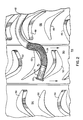
- Fig. 2 is a sectional representation of a portion of a turbine jet engine in which the borescope of this invention is employed for inspection purposes.
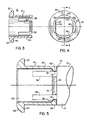
- Fig. 3 is a sectional view and Fig. 4 is a proximalto-distal end view of the hooking cap, Fig. 3 being taken along plane 3-3 in Fig. 4.
- Fig. 5 is a sectional view of a borescope and hooking cap in place on the distal tip of the borescope.
- Figs. 6 and 7 are a sectional elevation and an end view of a borescope end cap according to an alternative embodiment, Fig. 6 being taken along plane 6-6 of Fig. 7.
- Fig. 8 is an end view of a borescope and cap according to an additional embodiment of this invention.
- Fig. 1 shows a video borescope assembly 10 which comprises an elongated flexible insertion tube 12 that can be up to 50 feet (16 meters) in length and which has a viewing head 14 incorporated into its distal tip.
- This viewing head contains an optical lens and a miniature video camera.
- the latter can be formed of a CCD device or other solid-state imager capable of providing a full-color image of a remote target area e.g. the inside of a boiler tube heat exchanger or a stator vane of a jet engine or gas turbine.
- An example of a suitable solid-state imager is disclosed in U.S. Pat. No. 4,491,865.
- the cap 16 has a generally tubular sleeve 18 that overfits the borescope tip 14 and a radial flange 20 that extends outward from the distal end of the sleeve 18.
- a steering and control unit 22 that can be manipulated by an operator to bend a steering section 24 at the front or distal end of the insertion tube adjacent the viewing head 14.
- the control unit 22 couples the insertion tube 12 to a flexible tubular umbilical 26.
- a borescope interface module 28 of the plug-in type, substantially as disclosed in U.S. Pat. No. 4,539,586.
- the module 28 fits a mating receptacle in an auxiliary light box 30, which can be of the type disclosed in U.S. Pat. No. 4,583,774.
- This light box is coupled in turn to an auxiliary illumination source 32 by means of a suitable flexible light conduit 34.
- An auxiliary umbilical 36 which is a flexible sheath containing a plurality of conductors, extends from a rear side of the auxiliary light box 30 and has an auxiliary interface module 38 that fits a receptacle on a video processor unit 40. If the auxiliary light box is not needed, the module 28 can be plugged directly into the video processor unit 40. Also shown in Fig. 1 is an auxiliary video monitor 42, which can be remoted to the site of the auxiliary light box 30.
- the steering section 24 bends in one direction only, that is, to the left and to the right in a horizontal plane.
- a stripe 43 appears on the sheath of the insertion tube 12 and extends axially over the operative length of the insertion tube. This stripe 43 lies on the horizontal plane, i.e., the bending plane of the steering section 24. The stripe provides a visual indication to the operator of the orientation of the insertion tube 12 and steering section 24 when the borescope is inserted into an inaccessible area.
- Fig. 2 shows the distal end of the borescope insertion tube 12 after having penetrated into a jet engine 44 for inspection of same.
- the direction of gas flow is from right to left, so that the leading edges of the stator vanes and rotor blades are to the right, and their trailing edges are to the left.
- the engine 44 has a first stator row 46 formed of a plurality of spaced stator vanes 48, a rotor 50, on which there are a plurality of spaced rotor blades 52, and a second stator row 54 which has a plurality of spaced stator vanes 56.
- the vanes 48, 56, and blades 52 have rounded leading edges and pointed trailing edges.
- the first row stator vanes 48 and the rotor blades 52 can be inspected without difficulty. However, it is the leading edges of the stator vanes 56 of the second row that are most subject to hidden damage and it is these vanes 56 that require the subject probe for inspection.
- Rotor and stator elements behind the second stator row 54 have a low incidence of damage, making routine inspection unnecessary in most cases.
- the borescope insertion tube 12 is inserted through a guide tube (not shown) which has been inserted into an inspection port (not shown) of the engine 44.
- the guide tube positions the insertion tube to enter between a pair of the first row stator blades 48.
- the operator maintains the bending plane horizontal, i.e., to conform with the curve in the blades 52, by observing both the stripe 53 on the insertion tube and the image on the monitor.
- the insertion tube is passed between a pair of blades 52 of the rotor 50. Then, by manipulating the control unit 22, the operator latches the flange 20 of the cap 16 onto the trailing edge of one of the rotor blades 52.
- the rotor 50 is then slowly turned in the direction of the arrows of Fig. 2, and this carries the insertion tube so that the tip 14 passes each of the stator vanes 56 in succession. After these vanes 56 have been inspected, the rotor 50 is turned reversely back to its original position for withdrawal of the insertion tube 12. To unlatch the cap 16, the operator relaxes the bending section 24 and rotates the insertion tube 12. This causes the flange 20 to roll out of engagement with the trailing edge of the blade 52.
- the generally mushroom-shaped hook cap 16 of this invention is far easier to employ, in terms of both making the necessary engagement with and disengagement from the rotor blade trailing edges. Also, because the cap 16 employs no moving parts which must be manipulated through a forceps channel or air conduit, the borescope insertion tube can be made without provision for such conduits or channels. Thus, with this invention, the borescope that is employed can be made thinner and more flexible than was possible previously.
- the sleeve 18 is generally cylindrical and has a plurality of axial slots 58 which extend from the proximal or rear end part way towards the distal end, to define a plurality of fingers 60.
- a lip 62 At the proximal end of each of the fingers 60 there is a lip 62 that projects radially inward.
- Each lip 62 has chamferred proximal and distal sides which facilitate installation of the cap and break away of the cap from the insertion tube tip 14 if a predetermined force is exceeded.
- the break away provision permits the insertion tube 12 to be removed from the engine in case where the cap 16 becomes jammed. Because the cap 16 is formed entirely of soft aluminum, a material which becomes entirely consumed at the combustion temperatures of the jet engine, a lost cap 16 can remain in the engine without threat of damage to any of the rotor blades or stator vanes.
- the flange 20 is generally annular, that is, it has a circular profile, with an arcuate front or distal surface 64 and a flat back surface 66.
- the arcuate front surface 64 facilitates threading of the borescope through the passages of the jet engine 44, while the flat proximal surface 66 facilitates the hooking of the flange 20 onto the rotor blade 52.
- the probe head at the distal tip 14 has a distal or front section 68 of reduced diameter and a shoulder 70 which connects to a proximal section 72 of a greater diameter.
- the proximal section 72 has the same diameter as the remainder of the insertion tube 12.
- transverse slots 74 provided at the shoulder 70 to receive the lips 62 of the cap 16. These transverse slots have chamferred distal sides 76 of predetermined slope to facilitate break away. It should be understood that the elasticity of the aluminum material, and the sizes of the slots 58 and degree of chamfer of the lips 62 and the surface 76 are selected so that a predetermined break away force is predictably established.
- a hooking cap 78 has a generally cylindrical sleeve 80 and a flange 82 that extends generally in the radial direction, but in which the proximal surface 84 is angled back somewhat, i.e. extending at least slightly in the proximal direction.
- the flange 82 is formed of a pair of oppositely directed lobes 86.
- the flange 82 occupies only predetermined portions of the circumference of the sleeve 80.
- the cap 78 is employed with a video type probe, in which a front or distal surface of the head or tip 14 has a video imager 88 or miniature video camera and a fiber optics illumination bundle 90.
- a video imager 88 or miniature video camera and a fiber optics illumination bundle 90.
- the same type of hooking cap could be employed with equal facility on a so-called fiberscope, that is, on the type of borescope in which a fiber optic bundle carries an image to the viewing device disposed at the proximal end of the probe.
- a generally octagonal flange 20′ extends radially outward from the sleeve 18′. While this flange 20′ has the profile of a regular octagon, the flange in other embodiments could have any polygonal form, regular or irregular. In still other embodiments, the flange can be formed directly on the distal tip of the borescope, or the cap can be permanently affixed onto the distal tip.
Landscapes
- Physics & Mathematics (AREA)
- Astronomy & Astrophysics (AREA)
- General Physics & Mathematics (AREA)
- Optics & Photonics (AREA)
- Instruments For Viewing The Inside Of Hollow Bodies (AREA)
- Endoscopes (AREA)
Applications Claiming Priority (2)
| Application Number | Priority Date | Filing Date | Title |
|---|---|---|---|
| US07/451,016 US5052803A (en) | 1989-12-15 | 1989-12-15 | Mushroom hook cap for borescope |
| US451016 | 1989-12-15 |
Publications (1)
| Publication Number | Publication Date |
|---|---|
| EP0433181A1 true EP0433181A1 (fr) | 1991-06-19 |
Family
ID=23790458
Family Applications (1)
| Application Number | Title | Priority Date | Filing Date |
|---|---|---|---|
| EP90420401A Withdrawn EP0433181A1 (fr) | 1989-12-15 | 1990-09-11 | Capuchon à étage pour boroscope |
Country Status (3)
| Country | Link |
|---|---|
| US (1) | US5052803A (fr) |
| EP (1) | EP0433181A1 (fr) |
| JP (1) | JP2772867B2 (fr) |
Cited By (2)
| Publication number | Priority date | Publication date | Assignee | Title |
|---|---|---|---|---|
| EP1371812A1 (fr) * | 2002-06-04 | 2003-12-17 | ALSTOM (Switzerland) Ltd | Procédé de réparation pour les aubes d'une turbine à gaz |
| GB2455804A (en) * | 2007-12-21 | 2009-06-24 | Oliver Crispin Robotics Ltd | A robotic arm for use with a rotary machine |
Families Citing this family (35)
| Publication number | Priority date | Publication date | Assignee | Title |
|---|---|---|---|---|
| WO1995004254A1 (fr) * | 1993-07-29 | 1995-02-09 | Fraunhofer-Gesellschaft zur Förderung der angewandten Forschung e.V. | Dispositif de mesure tridimensionnelle pour cavites inaccessibles |
| US5487661A (en) * | 1993-10-08 | 1996-01-30 | Dentsply International, Inc. | Portable dental camera and system |
| US5644394A (en) * | 1994-10-19 | 1997-07-01 | United Technologies Corporation | System for repairing damaged gas turbine engine airfoils |
| JP3999402B2 (ja) * | 1998-06-09 | 2007-10-31 | 三菱重工業株式会社 | 蒸気タービンの異材溶接ロータ |
| US6532840B2 (en) * | 2000-12-19 | 2003-03-18 | General Electric Company | Methods for robotically inspecting gas turbine combustion components |
| US7262797B2 (en) * | 2001-02-22 | 2007-08-28 | Ge Inspection Technologies Lp | Method and system for storing calibration data within image files |
| NL1018974C2 (nl) * | 2001-09-18 | 2003-04-04 | Kema Nv | Werkwijze en inrichting voor het onderzoeken van de rek van langwerpige lichamen. |
| US7170677B1 (en) | 2002-01-25 | 2007-01-30 | Everest Vit | Stereo-measurement borescope with 3-D viewing |
| EP1618736A2 (fr) * | 2003-01-29 | 2006-01-25 | Everest-VIT, Inc. | Systeme d'inspection video a distance |
| US20040183900A1 (en) * | 2003-03-20 | 2004-09-23 | Everest Vit | Method and system for automatically detecting defects in remote video inspection applications |
| US7422559B2 (en) | 2004-06-16 | 2008-09-09 | Ge Inspection Technologies, Lp | Borescope comprising fluid supply system |
| US20060038988A1 (en) * | 2004-08-20 | 2006-02-23 | General Electric Company | Borescope assembly for detecting a condition of a rotating part |
| US7956888B2 (en) * | 2005-06-22 | 2011-06-07 | Ge Inspection Technologies, Lp | Remote video inspection system integrating audio communication functionality |
| WO2007002526A1 (fr) * | 2005-06-24 | 2007-01-04 | Everest Vit, Inc. | Carrousel de rangement pour tube d'insertion |
| US20070156021A1 (en) * | 2005-09-14 | 2007-07-05 | Bradford Morse | Remote imaging apparatus having an adaptive lens |
| US20070091183A1 (en) * | 2005-10-21 | 2007-04-26 | Ge Inspection Technologies, Lp | Method and apparatus for adapting the operation of a remote viewing device to correct optical misalignment |
| US7679041B2 (en) * | 2006-02-13 | 2010-03-16 | Ge Inspection Technologies, Lp | Electronic imaging device with photosensor arrays |
| US8310533B2 (en) * | 2006-03-27 | 2012-11-13 | GE Sensing & Inspection Technologies, LP | Inspection apparatus for inspecting articles |
| US8213676B2 (en) | 2006-12-20 | 2012-07-03 | Ge Inspection Technologies Lp | Inspection apparatus method and apparatus comprising motion responsive control |
| US8810636B2 (en) | 2006-12-20 | 2014-08-19 | Ge Inspection Technologies, Lp | Inspection apparatus method and apparatus comprising selective frame output |
| US9633426B2 (en) | 2014-05-30 | 2017-04-25 | General Electric Company | Remote visual inspection image capture system and method |
| US8118733B2 (en) * | 2006-12-22 | 2012-02-21 | Ge Inspection Technologies, Lp | Heat protection systems and methods for remote viewing devices |
| US8625434B2 (en) | 2006-12-29 | 2014-01-07 | Ge Inspection Technologies Lp | IP based voice communication enabled inspection system |
| US8514278B2 (en) | 2006-12-29 | 2013-08-20 | Ge Inspection Technologies Lp | Inspection apparatus having illumination assembly |
| US8310604B2 (en) | 2007-10-26 | 2012-11-13 | GE Sensing & Inspection Technologies, LP | Visual inspection apparatus having light source bank |
| US8767060B2 (en) * | 2007-10-26 | 2014-07-01 | Ge Inspection Technologies, Lp | Inspection apparatus having heat sink assembly |
| US8253782B2 (en) * | 2007-10-26 | 2012-08-28 | Ge Inspection Technologies, Lp | Integrated storage for industrial inspection handset |
| US7902990B2 (en) * | 2007-10-26 | 2011-03-08 | Ge Inspection Technologies, Lp | Battery and power management for industrial inspection handset |
| US20100198876A1 (en) | 2009-02-02 | 2010-08-05 | Honeywell International, Inc. | Apparatus and method of embedding meta-data in a captured image |
| FR2942267B1 (fr) * | 2009-02-19 | 2011-05-06 | Turbomeca | Temoin d'erosion pour roue de compresseur |
| US9519814B2 (en) | 2009-06-12 | 2016-12-13 | Hand Held Products, Inc. | Portable data terminal |
| US8602722B2 (en) * | 2010-02-26 | 2013-12-10 | General Electric Company | System and method for inspection of stator vanes |
| US10598917B2 (en) | 2017-04-07 | 2020-03-24 | United Technologies Corporation | Borescope grip |
| US12195202B1 (en) * | 2024-01-26 | 2025-01-14 | General Electric Company | System and method for servicing aircraft engines |
| US12186848B1 (en) | 2024-01-26 | 2025-01-07 | General Electric Company | Method and apparatus for servicing engines |
Citations (6)
| Publication number | Priority date | Publication date | Assignee | Title |
|---|---|---|---|---|
| US3841764A (en) * | 1969-12-09 | 1974-10-15 | Secr Defence | Intrascope |
| GB2036363A (en) * | 1978-12-04 | 1980-06-25 | United Technologies Corp | Inspecting Stator Vanes |
| US4298312A (en) * | 1979-07-24 | 1981-11-03 | Purex Corporation | Damaged vane locating method and apparatus |
| US4686963A (en) * | 1986-03-05 | 1987-08-18 | Circon Corporation | Torsion resistant vertebrated probe of simple construction |
| EP0242428A2 (fr) * | 1986-04-21 | 1987-10-28 | Identechs, Inc. | Appareil pour un endoscope propulsé par fluide |
| US4848817A (en) * | 1986-11-10 | 1989-07-18 | Olympus Optical Co., Ltd. | Hook forceps apparatus for industrial endoscopes |
Family Cites Families (2)
| Publication number | Priority date | Publication date | Assignee | Title |
|---|---|---|---|---|
| JPS60230113A (ja) * | 1984-04-27 | 1985-11-15 | Olympus Optical Co Ltd | 内視鏡用ガイドチユ−ブ |
| JPS62132511U (fr) * | 1986-02-12 | 1987-08-21 |
-
1989
- 1989-12-15 US US07/451,016 patent/US5052803A/en not_active Expired - Fee Related
-
1990
- 1990-09-11 EP EP90420401A patent/EP0433181A1/fr not_active Withdrawn
- 1990-11-15 JP JP2310141A patent/JP2772867B2/ja not_active Expired - Lifetime
Patent Citations (6)
| Publication number | Priority date | Publication date | Assignee | Title |
|---|---|---|---|---|
| US3841764A (en) * | 1969-12-09 | 1974-10-15 | Secr Defence | Intrascope |
| GB2036363A (en) * | 1978-12-04 | 1980-06-25 | United Technologies Corp | Inspecting Stator Vanes |
| US4298312A (en) * | 1979-07-24 | 1981-11-03 | Purex Corporation | Damaged vane locating method and apparatus |
| US4686963A (en) * | 1986-03-05 | 1987-08-18 | Circon Corporation | Torsion resistant vertebrated probe of simple construction |
| EP0242428A2 (fr) * | 1986-04-21 | 1987-10-28 | Identechs, Inc. | Appareil pour un endoscope propulsé par fluide |
| US4848817A (en) * | 1986-11-10 | 1989-07-18 | Olympus Optical Co., Ltd. | Hook forceps apparatus for industrial endoscopes |
Cited By (2)
| Publication number | Priority date | Publication date | Assignee | Title |
|---|---|---|---|---|
| EP1371812A1 (fr) * | 2002-06-04 | 2003-12-17 | ALSTOM (Switzerland) Ltd | Procédé de réparation pour les aubes d'une turbine à gaz |
| GB2455804A (en) * | 2007-12-21 | 2009-06-24 | Oliver Crispin Robotics Ltd | A robotic arm for use with a rotary machine |
Also Published As
| Publication number | Publication date |
|---|---|
| JP2772867B2 (ja) | 1998-07-09 |
| JPH03191311A (ja) | 1991-08-21 |
| US5052803A (en) | 1991-10-01 |
Similar Documents
| Publication | Publication Date | Title |
|---|---|---|
| US5052803A (en) | Mushroom hook cap for borescope | |
| US5066122A (en) | Hooking cap for borescope | |
| US8400501B2 (en) | Inspection arrangement | |
| US4298312A (en) | Damaged vane locating method and apparatus | |
| US9867523B2 (en) | Surgical imaging device | |
| US6862945B2 (en) | Camera guide for video pipe inspection system | |
| US9778141B2 (en) | Video inspection system with deformable, self-supporting deployment tether | |
| CN106460548B (zh) | 用于离线工业燃气涡轮和其它发电机器的视觉检查的挠性绳位置跟踪摄像机检查系统 | |
| US4696544A (en) | Fiberscopic device for inspection of internal sections of construction, and method for using same | |
| US6036636A (en) | Endoscope with tip portion disposed on distal side of insertion portion | |
| CN107085294B (zh) | 检查涡轮发动机部件的光学设备和观察管 | |
| US9347855B2 (en) | Inspection arrangement | |
| EP0242428B1 (fr) | Appareil pour un endoscope propulsé par fluide | |
| JP2001501719A (ja) | コークス炉の内視鏡検査プローブ | |
| GB2036363A (en) | Inspecting Stator Vanes | |
| EP4249984A1 (fr) | Mécanisme de stabilisation d'outil et procédés associés | |
| JP3140542B2 (ja) | 異物回収用工業用内視鏡 | |
| JP4414508B2 (ja) | 内視鏡装置 | |
| JP2690934B2 (ja) | 内視鏡 | |
| JP2931329B2 (ja) | 内視鏡システム | |
| JP5424170B2 (ja) | 配管カメラ挿入補助具および通線補助具 | |
| JPH0532818Y2 (fr) | ||
| JP7049949B2 (ja) | 内視鏡用ガイドチューブ | |
| JP2000092472A (ja) | 管内検査用テレビカメラシステム | |
| CN113614329B (zh) | 飞行器涡轮机的反向旋转涡轮和用于对反向旋转涡轮转子进行无损检测的方法 |
Legal Events
| Date | Code | Title | Description |
|---|---|---|---|
| PUAI | Public reference made under article 153(3) epc to a published international application that has entered the european phase |
Free format text: ORIGINAL CODE: 0009012 |
|
| AK | Designated contracting states |
Kind code of ref document: A1 Designated state(s): DE FR GB IT |
|
| 17P | Request for examination filed |
Effective date: 19911112 |
|
| 17Q | First examination report despatched |
Effective date: 19930811 |
|
| STAA | Information on the status of an ep patent application or granted ep patent |
Free format text: STATUS: THE APPLICATION IS DEEMED TO BE WITHDRAWN |
|
| 18D | Application deemed to be withdrawn |
Effective date: 19940319 |