EP0433227A2 - Outil de formage pour le façonnage de trous de goujon dans une anode - Google Patents
Outil de formage pour le façonnage de trous de goujon dans une anode Download PDFInfo
- Publication number
- EP0433227A2 EP0433227A2 EP90810937A EP90810937A EP0433227A2 EP 0433227 A2 EP0433227 A2 EP 0433227A2 EP 90810937 A EP90810937 A EP 90810937A EP 90810937 A EP90810937 A EP 90810937A EP 0433227 A2 EP0433227 A2 EP 0433227A2
- Authority
- EP
- European Patent Office
- Prior art keywords
- cover plate
- anode
- shaped body
- stop
- projections
- Prior art date
- Legal status (The legal status is an assumption and is not a legal conclusion. Google has not performed a legal analysis and makes no representation as to the accuracy of the status listed.)
- Granted
Links
Images
Classifications
-
- C—CHEMISTRY; METALLURGY
- C25—ELECTROLYTIC OR ELECTROPHORETIC PROCESSES; APPARATUS THEREFOR
- C25C—PROCESSES FOR THE ELECTROLYTIC PRODUCTION, RECOVERY OR REFINING OF METALS; APPARATUS THEREFOR
- C25C3/00—Electrolytic production, recovery or refining of metals by electrolysis of melts
- C25C3/06—Electrolytic production, recovery or refining of metals by electrolysis of melts of aluminium
- C25C3/08—Cell construction, e.g. bottoms, walls, cathodes
- C25C3/12—Anodes
- C25C3/125—Anodes based on carbon
-
- Y—GENERAL TAGGING OF NEW TECHNOLOGICAL DEVELOPMENTS; GENERAL TAGGING OF CROSS-SECTIONAL TECHNOLOGIES SPANNING OVER SEVERAL SECTIONS OF THE IPC; TECHNICAL SUBJECTS COVERED BY FORMER USPC CROSS-REFERENCE ART COLLECTIONS [XRACs] AND DIGESTS
- Y10—TECHNICAL SUBJECTS COVERED BY FORMER USPC
- Y10S—TECHNICAL SUBJECTS COVERED BY FORMER USPC CROSS-REFERENCE ART COLLECTIONS [XRACs] AND DIGESTS
- Y10S425/00—Plastic article or earthenware shaping or treating: apparatus
- Y10S425/01—Core positioning
Definitions
- the invention relates to a mold for the formation of mortises in an anode according to the preamble of claim 1.
- the anode material is filled into a mold into which the shaped bodies of the generally known generic molding tools for forming the pin holes project at predetermined positions. After filling and pressing such a "green" anode, the shaping tools must be pulled out of the pin holes before they are fired.
- the inclined grooves formed by the projections of the respective molded body in the wall of the mortise are retained when the molding tool is removed, since the molded body with the external projections can rotate freely about the holding axis.
- the respective angular position of the projections after the removal of the molding tool is indefinite in that the molding can continue to rotate even after it has been freed from the anode.
- the invention is therefore based on the object of forming the generic type with structurally simple means so that its projections always form the grooves in the wall of the pin hole in the same angular position with respect to the anode produced.
- the configuration of the mold according to the invention ensures that the molded body can rotate when it is pulled out of the anode, the elastic means being tensioned, but without the pin holes being damaged. After pulling out of the anode, the shaped body is then rotated back into its starting position by the tensioned elastic means, in which it lies against the stop. Consequently, all the grooves formed by the protrusions of a shaped body in the wall of the pin holes of the anode are oriented identically in all the anodes produced, so that the grooves can be cleaned automatically in a simple manner.
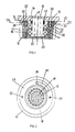
- the mold shown in FIGS. 1 to 3 has one Cover plate 10, on which a holding axis 12 is fastened at one end by means of fastening screws 48 passing axially through the holding axis 12.
- An essentially cylindrical shaped body 14 is rotatably mounted on the holding axis 12 by means of a lower and an upper radial bearing 16 or 18.
- tangential projections 40 are provided with the same slope with respect to the axis of the molded body 14.
- the outer race of the lower radial bearing 16 is held in the axial direction on the one hand by an inwardly extending bearing projection 46 of the molded body 14 and on the other hand by a bearing cover 20 screwed onto the molded body 14 on the side opposite the cover plate 10.
- the inner race of the lower radial bearing 16 is supported on the one hand on a spacer ring 44 and on the other hand on a bearing collar 22 provided at the lower end of the holding axis 12.
- the inner race of the upper radial bearing 18 is fixedly supported on the one hand by the spacer ring 44 and on the other hand by a spacer sleeve 42 which presses against the cover plate 10 with its other side.
- the outer race of the upper radial bearing 18 lies on the bearing projection 46.
- an upwardly open towards the cover plate 10 annular groove 24 is formed, which is concentric with the support axis 12.
- a cover ring 28 likewise concentric with the holding axis 12, is inserted into the molded body 14.
- the surface of the cover ring 28 is essentially flush with the surface of the shaped body 14.
- the cover ring 28 is connected to the cover plate in a rotationally fixed manner via a threaded pin 30.
- the cover ring 28 is dimensioned such that the molded body 14 can rotate about the holding axis 12 and the cover ring 28 without jamming with the latter.
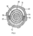
- a coil spring 26 is arranged so that its ends are in the stop position of the molded body 14 diametrically opposite.
- One end of the helical spring 26 is connected to the cover ring fixed to the cover plate 28 via a threaded pin 32, while the other end of the helical spring 26 is connected to the molded body 14 via a threaded bolt 34 screwed into the groove base 25 of the annular groove 24.
- a stop 38 is provided in the cover ring 28, which is formed by one end of a circular ring segment concentric with the retaining axis 12.
- a stop pin 36 attached to the groove base 25 of the annular groove 24 engages in the circular ring segment.
- the stop pin 36 is biased by the tensile force of the coil spring 26 against the end of the circular ring segment facing the threaded pin 32.
- the molded body 14 can, however, be rotated counter to the pulling direction of the helical spring 26 in such a way that the stop pin 36 fastened to it moves in the direction of the end of the circle segment opposite the stop 38, ie to the right in FIG. 2.
- the molding tool When pressing a "green” anode, the molding tool is inserted into a mold, the mold being closed at the top by the cover plate 10. After the pressing process, the cover plate 10 is lifted up together with the molded body 14. Because of the projections 40 on the circumferential wall of the molded body 14, which are inclined to its axis, the molded body 14 is guided by the grooves that have become dimensionally stable during the pressing, rotated against the direction of the tensile force of the helical spring 26, which is thereby further tensioned.
- the molded body 14 is rotated back by the prestressed helical spring 26 until the stop pin 36 on the end of the circular segment facing the threaded pin 32, i.e. on the stop 38, is present.
- the molded body 14 is now again in its stop position, in which the projections 40 are exactly the same angular position with respect to the anode to be pressed, as with the anode previously completed for firing.
- the tensile force of the helical spring 26 is designed so that the grooves of the pin hole formed by the shaped body 14 are not damaged when the shaped body 14 is pulled out of the anode and the shaped body 14 is rotated into its stop position after being pulled out of the anode.
- the exemplary embodiment was explained using a shaped body 14. In the manufacture of anodes, however, it is customary to provide at least two pin holes which are formed by the same shaped bodies 14 which are rotatably fastened to the cover plate in the manner described above.
Landscapes
- Chemical & Material Sciences (AREA)
- Engineering & Computer Science (AREA)
- Chemical Kinetics & Catalysis (AREA)
- Electrochemistry (AREA)
- Materials Engineering (AREA)
- Metallurgy (AREA)
- Organic Chemistry (AREA)
- Moulds, Cores, Or Mandrels (AREA)
- Electrical Discharge Machining, Electrochemical Machining, And Combined Machining (AREA)
- Electrolytic Production Of Metals (AREA)
- Vessels, Lead-In Wires, Accessory Apparatuses For Cathode-Ray Tubes (AREA)
Applications Claiming Priority (2)
| Application Number | Priority Date | Filing Date | Title |
|---|---|---|---|
| DE8914428U | 1989-12-07 | ||
| DE8914428U DE8914428U1 (de) | 1989-12-07 | 1989-12-07 | Formwerkzeug für die Ausbildung von Zapfenlöchern in einer Anode |
Publications (3)
| Publication Number | Publication Date |
|---|---|
| EP0433227A2 true EP0433227A2 (fr) | 1991-06-19 |
| EP0433227A3 EP0433227A3 (en) | 1991-08-21 |
| EP0433227B1 EP0433227B1 (fr) | 1994-03-09 |
Family
ID=6845269
Family Applications (1)
| Application Number | Title | Priority Date | Filing Date |
|---|---|---|---|
| EP90810937A Expired - Lifetime EP0433227B1 (fr) | 1989-12-07 | 1990-11-30 | Outil de formage pour le façonnage de trous de goujon dans une anode |
Country Status (7)
| Country | Link |
|---|---|
| US (1) | US5078587A (fr) |
| EP (1) | EP0433227B1 (fr) |
| CA (1) | CA2031604A1 (fr) |
| DE (2) | DE8914428U1 (fr) |
| ES (1) | ES2050997T3 (fr) |
| IS (1) | IS1588B (fr) |
| NO (1) | NO178830C (fr) |
Families Citing this family (3)
| Publication number | Priority date | Publication date | Assignee | Title |
|---|---|---|---|---|
| US8197545B2 (en) | 2005-10-27 | 2012-06-12 | Depuy Spine, Inc. | Nucleus augmentation delivery device and technique |
| US20070173935A1 (en) * | 2005-10-28 | 2007-07-26 | O'neil Michael J | Nucleus pulposus augmentation pretreatment technique |
| US20120076888A1 (en) * | 2010-09-28 | 2012-03-29 | Cheng Uei Precision Industry Co., Ltd. | Mould with the contact prepressing and positioning function |
Family Cites Families (8)
| Publication number | Priority date | Publication date | Assignee | Title |
|---|---|---|---|---|
| US716343A (en) * | 1901-05-08 | 1902-12-16 | Fred M Locke | Machine for forming the interior of plastic materials. |
| US1379328A (en) * | 1920-04-09 | 1921-05-24 | William J Baird | Molding-machine |
| US3150222A (en) * | 1961-05-16 | 1964-09-22 | Phillips Petroleum Co | Molding threaded articles |
| US3398081A (en) * | 1966-04-05 | 1968-08-20 | Pechiney Prod Chimiques Sa | Prebaked carbon anodes and anode assembly for the production of aluminum |
| DE1937411B1 (de) * | 1969-07-23 | 1971-09-16 | Bard Martin Dipl Ing | Befestigung zwischen einem anodenzapfen und einer kohlen stoffanode |
| US3730664A (en) * | 1971-11-24 | 1973-05-01 | Eyelet Specialty Co | Mold apparatus for making a closure cap |
| US4268003A (en) * | 1977-11-02 | 1981-05-19 | Liautaud James P | Mold core and method and apparatus for manufacture |
| US4842508A (en) * | 1988-08-15 | 1989-06-27 | Borislav Boskovic | Core insert actuator |
-
1989
- 1989-12-07 DE DE8914428U patent/DE8914428U1/de not_active Expired - Lifetime
-
1990
- 1990-11-30 US US07/621,078 patent/US5078587A/en not_active Expired - Fee Related
- 1990-11-30 DE DE90810937T patent/DE59004906D1/de not_active Expired - Fee Related
- 1990-11-30 ES ES90810937T patent/ES2050997T3/es not_active Expired - Lifetime
- 1990-11-30 EP EP90810937A patent/EP0433227B1/fr not_active Expired - Lifetime
- 1990-12-05 NO NO905258A patent/NO178830C/no unknown
- 1990-12-05 CA CA002031604A patent/CA2031604A1/fr not_active Abandoned
- 1990-12-06 IS IS3650A patent/IS1588B/is unknown
Also Published As
| Publication number | Publication date |
|---|---|
| EP0433227A3 (en) | 1991-08-21 |
| ES2050997T3 (es) | 1994-06-01 |
| NO178830C (no) | 1996-06-12 |
| NO178830B (no) | 1996-03-04 |
| DE8914428U1 (de) | 1990-02-01 |
| EP0433227B1 (fr) | 1994-03-09 |
| DE59004906D1 (de) | 1994-04-14 |
| CA2031604A1 (fr) | 1991-06-08 |
| IS1588B (is) | 1996-03-01 |
| NO905258L (no) | 1991-06-10 |
| IS3650A7 (is) | 1991-06-08 |
| US5078587A (en) | 1992-01-07 |
| NO905258D0 (no) | 1990-12-05 |
Similar Documents
| Publication | Publication Date | Title |
|---|---|---|
| EP0632699B1 (fr) | Dispositif a pression pour le blocage de lacets | |
| DE3344281C2 (de) | Spulenkörper für ein Bandmaß | |
| DE3732674C2 (fr) | ||
| DE3200612C2 (de) | Riemenspannvorrichtung | |
| DE2732654A1 (de) | Gelenkbeschlag fuer leiterteile | |
| DE2829433C2 (de) | Schraubengetriebe | |
| DE1577278A1 (de) | Verfahren und Vorrichtung zum Verpressen pulverfoermiger Materialien | |
| DE3420551C2 (de) | Matrize zum Formen von stapelbaren Behältern | |
| EP1109983A1 (fr) | Charniere a visser comportant une position d'arret | |
| DE2442010C2 (de) | Kraftstoffeinspritzpumpe für Brennkraftmaschinen | |
| EP0433227B1 (fr) | Outil de formage pour le façonnage de trous de goujon dans une anode | |
| DE3005968C2 (de) | Fadenschneider | |
| DE1954337B2 (de) | Glattwalzwerkzeug für zylindrische Werkstückoberflächen | |
| DE8002866U1 (de) | Spaetzlepresse | |
| DE3516644A1 (de) | Permutationsschloss fuer koffer oder dergleichen | |
| EP0697181A2 (fr) | Bâton adhésif avec dispositif de maintien du bâton en forme de piston | |
| DE8401094U1 (de) | Presswerkzeug zum sichern von schraubverbindungen | |
| DE2302452B2 (de) | Rastwerk für einen Stufendrehschalter | |
| DE3734502C2 (fr) | ||
| DE3504892C2 (de) | Steckverbindung-Vorrichtung zur Befestigung des Kopfes eines Winkelstücks am Hauptteil des Winkelstücks eines zahnärztlichen Arbeitsgeräts | |
| DE69502226T2 (de) | Markiervorrichtung mit einem bewegbaren indexierbaren Einsatz für Spritzgiessform | |
| DE3731554A1 (de) | Angelrolle | |
| DE2149014A1 (de) | Wischkopf fuer eine Wischvorrichtung und Verfahren zur Herstellung des Wischkopfes | |
| DE2321346B2 (de) | Gelenkbeschlag für klappbare Leitern | |
| AT360489B (de) | Reinigungsbuerste |
Legal Events
| Date | Code | Title | Description |
|---|---|---|---|
| PUAI | Public reference made under article 153(3) epc to a published international application that has entered the european phase |
Free format text: ORIGINAL CODE: 0009012 |
|
| AK | Designated contracting states |
Kind code of ref document: A2 Designated state(s): CH DE ES FR GB IT LI NL |
|
| PUAL | Search report despatched |
Free format text: ORIGINAL CODE: 0009013 |
|
| AK | Designated contracting states |
Kind code of ref document: A3 Designated state(s): CH DE ES FR GB IT LI NL |
|
| 17P | Request for examination filed |
Effective date: 19920120 |
|
| 17Q | First examination report despatched |
Effective date: 19930305 |
|
| ITF | It: translation for a ep patent filed | ||
| GRAA | (expected) grant |
Free format text: ORIGINAL CODE: 0009210 |
|
| RAP1 | Party data changed (applicant data changed or rights of an application transferred) |
Owner name: ALUSUISSE ITALIA S.P.A. |
|
| AK | Designated contracting states |
Kind code of ref document: B1 Designated state(s): CH DE ES FR GB IT LI NL |
|
| REF | Corresponds to: |
Ref document number: 59004906 Country of ref document: DE Date of ref document: 19940414 |
|
| GBT | Gb: translation of ep patent filed (gb section 77(6)(a)/1977) |
Effective date: 19940408 |
|
| REG | Reference to a national code |
Ref country code: ES Ref legal event code: FG2A Ref document number: 2050997 Country of ref document: ES Kind code of ref document: T3 |
|
| ET | Fr: translation filed | ||
| PLBE | No opposition filed within time limit |
Free format text: ORIGINAL CODE: 0009261 |
|
| STAA | Information on the status of an ep patent application or granted ep patent |
Free format text: STATUS: NO OPPOSITION FILED WITHIN TIME LIMIT |
|
| 26N | No opposition filed | ||
| PGFP | Annual fee paid to national office [announced via postgrant information from national office to epo] |
Ref country code: GB Payment date: 19991020 Year of fee payment: 10 |
|
| PGFP | Annual fee paid to national office [announced via postgrant information from national office to epo] |
Ref country code: ES Payment date: 19991112 Year of fee payment: 10 |
|
| PGFP | Annual fee paid to national office [announced via postgrant information from national office to epo] |
Ref country code: FR Payment date: 19991117 Year of fee payment: 10 |
|
| PGFP | Annual fee paid to national office [announced via postgrant information from national office to epo] |
Ref country code: NL Payment date: 19991123 Year of fee payment: 10 |
|
| PGFP | Annual fee paid to national office [announced via postgrant information from national office to epo] |
Ref country code: CH Payment date: 19991129 Year of fee payment: 10 |
|
| PGFP | Annual fee paid to national office [announced via postgrant information from national office to epo] |
Ref country code: DE Payment date: 19991130 Year of fee payment: 10 |
|
| PG25 | Lapsed in a contracting state [announced via postgrant information from national office to epo] |
Ref country code: LI Free format text: LAPSE BECAUSE OF NON-PAYMENT OF DUE FEES Effective date: 20001130 Ref country code: GB Free format text: LAPSE BECAUSE OF NON-PAYMENT OF DUE FEES Effective date: 20001130 Ref country code: CH Free format text: LAPSE BECAUSE OF NON-PAYMENT OF DUE FEES Effective date: 20001130 |
|
| PG25 | Lapsed in a contracting state [announced via postgrant information from national office to epo] |
Ref country code: ES Free format text: LAPSE BECAUSE OF NON-PAYMENT OF DUE FEES Effective date: 20001201 |
|
| PG25 | Lapsed in a contracting state [announced via postgrant information from national office to epo] |
Ref country code: NL Free format text: LAPSE BECAUSE OF NON-PAYMENT OF DUE FEES Effective date: 20010601 |
|
| REG | Reference to a national code |
Ref country code: CH Ref legal event code: PL |
|
| GBPC | Gb: european patent ceased through non-payment of renewal fee |
Effective date: 20001130 |
|
| PG25 | Lapsed in a contracting state [announced via postgrant information from national office to epo] |
Ref country code: FR Free format text: LAPSE BECAUSE OF NON-PAYMENT OF DUE FEES Effective date: 20010731 |
|
| NLV4 | Nl: lapsed or anulled due to non-payment of the annual fee |
Effective date: 20010601 |
|
| PG25 | Lapsed in a contracting state [announced via postgrant information from national office to epo] |
Ref country code: DE Free format text: LAPSE BECAUSE OF NON-PAYMENT OF DUE FEES Effective date: 20010801 |
|
| REG | Reference to a national code |
Ref country code: FR Ref legal event code: ST |
|
| REG | Reference to a national code |
Ref country code: ES Ref legal event code: FD2A Effective date: 20011214 |
|
| PG25 | Lapsed in a contracting state [announced via postgrant information from national office to epo] |
Ref country code: IT Free format text: LAPSE BECAUSE OF NON-PAYMENT OF DUE FEES;WARNING: LAPSES OF ITALIAN PATENTS WITH EFFECTIVE DATE BEFORE 2007 MAY HAVE OCCURRED AT ANY TIME BEFORE 2007. THE CORRECT EFFECTIVE DATE MAY BE DIFFERENT FROM THE ONE RECORDED. Effective date: 20051130 |