EP0433494A1 - Briquet - Google Patents
Briquet Download PDFInfo
- Publication number
- EP0433494A1 EP0433494A1 EP89123831A EP89123831A EP0433494A1 EP 0433494 A1 EP0433494 A1 EP 0433494A1 EP 89123831 A EP89123831 A EP 89123831A EP 89123831 A EP89123831 A EP 89123831A EP 0433494 A1 EP0433494 A1 EP 0433494A1
- Authority
- EP
- European Patent Office
- Prior art keywords
- nozzle
- vaporizer
- valve
- burner unit
- lighter
- Prior art date
- Legal status (The legal status is an assumption and is not a legal conclusion. Google has not performed a legal analysis and makes no representation as to the accuracy of the status listed.)
- Withdrawn
Links
- 239000002184 metal Substances 0.000 claims abstract description 17
- 238000005192 partition Methods 0.000 claims abstract description 4
- 239000001273 butane Substances 0.000 claims description 22
- IJDNQMDRQITEOD-UHFFFAOYSA-N n-butane Chemical compound CCCC IJDNQMDRQITEOD-UHFFFAOYSA-N 0.000 claims description 22
- OFBQJSOFQDEBGM-UHFFFAOYSA-N n-pentane Natural products CCCCC OFBQJSOFQDEBGM-UHFFFAOYSA-N 0.000 claims description 22
- 239000000446 fuel Substances 0.000 claims description 10
- 239000007788 liquid Substances 0.000 claims description 8
- 239000002828 fuel tank Substances 0.000 claims description 4
- 239000000203 mixture Substances 0.000 abstract description 14
- 239000003570 air Substances 0.000 abstract description 9
- 238000004519 manufacturing process Methods 0.000 abstract description 5
- 230000008016 vaporization Effects 0.000 abstract description 5
- 239000012080 ambient air Substances 0.000 abstract description 4
- 239000006200 vaporizer Substances 0.000 description 16
- 239000007789 gas Substances 0.000 description 15
- 239000004575 stone Substances 0.000 description 7
- 230000007246 mechanism Effects 0.000 description 5
- 230000007812 deficiency Effects 0.000 description 4
- 230000001276 controlling effect Effects 0.000 description 3
- 238000010438 heat treatment Methods 0.000 description 3
- QVGXLLKOCUKJST-UHFFFAOYSA-N atomic oxygen Chemical compound [O] QVGXLLKOCUKJST-UHFFFAOYSA-N 0.000 description 2
- 239000000470 constituent Substances 0.000 description 2
- 230000006735 deficit Effects 0.000 description 2
- 230000000994 depressogenic effect Effects 0.000 description 2
- 239000001301 oxygen Substances 0.000 description 2
- 229910052760 oxygen Inorganic materials 0.000 description 2
- 210000003813 thumb Anatomy 0.000 description 2
- ZMJBYMUCKBYSCP-UHFFFAOYSA-N Hydroxycitric acid Chemical compound OC(=O)C(O)C(O)(C(O)=O)CC(O)=O ZMJBYMUCKBYSCP-UHFFFAOYSA-N 0.000 description 1
- 230000009172 bursting Effects 0.000 description 1
- 235000019506 cigar Nutrition 0.000 description 1
- 235000019504 cigarettes Nutrition 0.000 description 1
- 238000005253 cladding Methods 0.000 description 1
- 238000010276 construction Methods 0.000 description 1
- 230000001419 dependent effect Effects 0.000 description 1
- 230000003292 diminished effect Effects 0.000 description 1
- 230000000694 effects Effects 0.000 description 1
- 230000001771 impaired effect Effects 0.000 description 1
- 230000001105 regulatory effect Effects 0.000 description 1
- 230000035939 shock Effects 0.000 description 1
- 235000019505 tobacco product Nutrition 0.000 description 1
- 238000009834 vaporization Methods 0.000 description 1
Images

Classifications
-
- F—MECHANICAL ENGINEERING; LIGHTING; HEATING; WEAPONS; BLASTING
- F23—COMBUSTION APPARATUS; COMBUSTION PROCESSES
- F23Q—IGNITION; EXTINGUISHING-DEVICES
- F23Q2/00—Lighters containing fuel, e.g. for cigarettes
- F23Q2/28—Lighters characterised by electrical ignition of the fuel
- F23Q2/285—Lighters characterised by electrical ignition of the fuel with spark ignition
- F23Q2/287—Lighters characterised by electrical ignition of the fuel with spark ignition piezoelectric
-
- F—MECHANICAL ENGINEERING; LIGHTING; HEATING; WEAPONS; BLASTING
- F23—COMBUSTION APPARATUS; COMBUSTION PROCESSES
- F23Q—IGNITION; EXTINGUISHING-DEVICES
- F23Q2/00—Lighters containing fuel, e.g. for cigarettes
- F23Q2/16—Lighters with gaseous fuel, e.g. the gas being stored in liquid phase
- F23Q2/162—Lighters with gaseous fuel, e.g. the gas being stored in liquid phase with non-adjustable gas flame
- F23Q2/163—Burners (gas valves)
Definitions
- the invention relates to lighter devices of the well-known type wherein on actuation thereof a jet of a suitable fuel such as pressurized liquid butane gas will burst out from a nozzle-valve aggregate and will be met by ignition sparks simultaneously generated by an associated ignition system whereby to provide a burning flame, e.g. for lighting tobacco products such as cigarettes or cigars.
- a suitable fuel such as pressurized liquid butane gas
- butane gas lighters there are essentially two main types of such butane gas lighters, namely low standard disposable butane lighters (one way gas lighters), and high quality wind-proof butane lighters.
- the former type substantially have the following two main deficiencies: In the actuated condition the flame is burning directly on top of the nozzle from which the fuel bursts out, thereby directly heating the nozzle parts and tending to impair and ultimately destroy the rubber O-ring and rubber nail inside the nozzle-valve aggregate for controlling the butane gas flow. While this impairment of the nozzle parts may be tolerable to a certain degree in a disposable (one way) cheap lighter, it would obviously unduly limit the useful life of a better quality lighter device. Even in the low cost disposable devices this direct heating of the nozzle by the flame unduly limits the admissible strength of the flame to a very weak flame. This in turn causes the second deficiency of this type of lighter, namely its inherent lack of wind-proof characteristics inasmuch the weak flame is undesirably subject to extinction by even light ambient wind impact.
- the long pipe will be directly heated by the flame burning on top of it which tends to impair and hurt the rubber cladding on the inside of the connector pipe and other assembled parts.
- the long connector pipe also provides direct heat transfer between the flame and the nozzle, with a tendency of the latter also becoming (indirectly) heated by the lighter flame, with concomitant damage to the nozzle parts.
- the invention thus relates to a lighter device of the general type comprising - a lower housing portion housing a fuel tank containing fuel under pressure, preferably pressurized butane liquid gas fuel, - a nozzle-and-valve aggregate connected with said fuel tank and arranged to project from said lower housing portion towards a burning space provided in the upper portion of the lighter, - a burning system comprising a tube-like burner member associated with and arranged above said nozzle-and-valve aggregate, - an ignition system preferably mounted on the upper portion of the lighter and arranged to provide, on actuation thereof, ignition sparks to said burning space, - actuating means for said valve of said nozzle-and-valve aggregate, for switching said valve from its normally closed condition into its open condition, in dependence on and coordination wit actuation of said ignition system, whereby to permit a jet of said pressurized fuel to burst out from said nozzle towards said burning space.
- - said burning system comprises a combined tube-like vaporizer-and-burner unit axially aligned with the nozzle-and-valve aggregate, - said tube-like vaporizer-and-burner unit is vertically positioned with its lower end at a predetermined free distance above said nozzle-and-valve aggregate and cleared therefrom by said free distance, - the lower end of said tube-like vaporizer-and-burner unit has a diameter larger than the diameter of said nozzle.
- the short tube vaporizer and burner unit is provided as a separate member mounted separately and independent from the nozzle valve; thus there is no direct mechanical connection and correspondingly no direct heat conduction or heat transfer between the burner unit and the nozzle and valve aggregate, whereby impairment of the latter by heat from the burner unit is effectively avoided or diminished.
- there will be no undue limitation on the size and temperature admissible for the flame which therefore can be a strong, hot, blue-colour flame which in itself has a substantial wind-proof capability.
- the strong flame is also enabled by the feature that the lower end of the vaporizer-and-burner unit arranged in a predetermined distance above the nozzle has a larger diameter than the nozzle whereby the jet stream bursting out from the nozzle will be substantially completely received in the lower end of the vaporizer unit and simultaneously will draw ambient air into the vaporizer-and-burning unit whereby to intensely mixing and vaporizing the butane gas/air mixture.
- said combined tube-like vaporizer-and-burner unit is partitioned into two axially aligned compartments by a horizontally extending perforated partition wall, preferably a piece of perforated metal sheet.
- This perforated metal sheet effectively contributes to further intensely mix and vaporize the butane/air mixture, thus providing for a particularly efficient type of "turbo"-burning.
- a catalyzer wire is provided within said tube-like combined vaporizer-and-burner unit in the upper section thereof.
- the invention provides for a simple to manufacture lighter which will provide reliable operation over an extended long useful life, and has improved wind-proof characteristics by an automatic re-igniting capability.
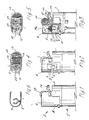
- the lighter of the present invention comprises, in a manner general known, a lower portion generally designated at 1 and an upper portion generally designated at 2.
- Lower portion 1 in conventional manner forms, or contains, the tank for the fuel used, preferably liquid butane gas under pressure, or some other conventional lighter fuel.
- the lighter upper portion 2 comprises upper seat member 3 mounting the (conventional) ignition and actuation mechanisms and the nozzle and valve mechanism to be described further below, and wind shield 4 mounting and enclosing the specific vaporizer and burner members of the present invention to be described hereinafter.
- the vaporizer and burner unit of the present invention is in the form of a short metal tube member generally designated at 5.
- Vaporizer and burner unit 5 in the preferred embodiment as shown and described consists of two relatively short tube sections 6,7 arranged coaxially with one another one above the other along the common axis.
- the two sections 6,7 form a unitary structure.
- the forementioned unitary vaporizer and burner structure 5 is mounted on wind-shield 4, by means of a horse-shoe-shaped mounting or holding member 8 which as is best seen from Fig. 6 horizontally extends inwardly from the inner wall of wind-shield 4, and accommodates, with its horse-shoe-shaped portion, the vaporizer and burning unit 5 at a predetermined vertical height within wind-shield housing 4, as hereinafter described.
- the two tube sections 6,7 of the short metal tube aggregate 5 have different diameters, the upper tube section 7 having a larger diameter than the lower tube section 6, whereby a step 9 is formed at the junction of the two tube sections. Horizontal step 9 thus formed provides a convenient mounting face which rests upon, and is affixed to, the horse-shoe-shaped portion of mounting and holding member 8.
- the (substantially conventional) nozzle and valve aggregate 10 is arranged in the upper portion of the left part (as shown in the drawing) of upper seat member 3, with nozzle 10 projecting from and above the upper end of said left portion of upper seat member 3.
- a conventional flow regulator 11 for controlling the flow volume of liquid butane gas passing through nozzle 10 in its open condition and thus regulating the size of the flame, is associated with the nozzle and valve aggregate 10 and projects horizontally from the side wall of the lighter casing, for actuation by the user to control the flow volume and thereby the size of the flame.
- ignition and actuation mechanisms are mounted on the right hand portion (as shown in the drawings) of upper seat member 3.
- the ignition mechanism is of the well-known mechanical type comprising a hand-actuated ignition wheel or drum 11 and a flint 12 arranged for cooperation therewith.
- ignition wheel or drum 11 comprises two knurled end sections 12,13 of slightly larger diameter for actuation by the user, and a main section 14 of slightly smaller diameter and having a suitably roughened surface whereby to struck ignition sparks from a flint stone 15 arranged to cooperate with the ignition wheel, on actuation thereof.
- Ignition wheel or drum 11 slightly projects from the upper end of wind-shield 4, for actuation by the user, and flint stone 15 is preferably arranged below the horizontally mounted ignition wheel or drum 11 in a manner that ignition sparks when generated on actuation of wheel or drum 11 will be directed towards the upper end of vaporizer and burner unit 5 within wind-shield 4.
- the (substantially conventional) actuating mechanism for nozzle and valve aggregate 10, in the embodiment described comprises an actuating lever 16 swivably mounted below ignition wheel/flint stone aggregat 11,15 and substantially extending horizontally.
- actuating lever 16 At its right end (as shown in the figures) actuating lever 16 is provided with a larger actuating portion 17 suitably associated with ignition wheel or drum 11 in a manner that if the user actuates, with the thumb of the hand holding the lighter, ignition wheel 11, the thumb will come to press upon actuating portion 17 of lever 16 whereby to press lever 7 to swivel from the substantially horizontal normal or rest position shown in Fig. 1,2 and 3, into the actuated position shown in Fig.
- actuating lever 16 is shown swivelled in the clock-wise direction about its pivot 18.
- actuation lever 16 pivotably engages with the upper end 19a on the vertical arm of a substantially L-shaped bracket 19, the lower substantially horizontal arm 20 of which engages with the nozzle and valve aggregate 10 for actuation thereof between a closed valve condition as shown in Fig. 1 through 3 and an open valve condition as shown in Fig. 8.
- the short-tube vaporizer and burner unit 5 with its vertical longitudinal axis aligned with nozzle and valve aggregate 10, is arranged vertically such that the lower end of unit 5 (i.e. the lower end of the lower tube section 6 of unit 5) will be in a predetermined free height above nozzle 10.
- the lower end of unit 5 i.e. the lower end of the lower tube section 6 of unit 5
- the diameter of the lower end 6 of vaporizer and burner unit 5 will be larger than the diameter of nozzle 10 of the butane gas tank whereby the (liquid) butane gas jet ejected from nozzle 10 (in the actuated open valve condition thereof) on its way upward into vaporizing and burner unit 5 will draw a stream of ambient air into unit 5, for intensive mixing with, and vaporizing of, the butane gas stream in the lower part of unit 5.
- a piece of perforated metal sheet is provided horizontally at the junction between the upper and lower sections 7,6 of unit 5.
- This perforated metal sheet 21 is best shown in Fig. 3, and the perforations 22 are best shown in the enlarged scale top view of Fig. 7.
- This perforated metal sheet effectively contributes to further intensely mix and vaporize the butane-air mixture, thus providing for a particularly efficient type of "turbo"-burning.
- a catalyzer wire 23 is provided centrally in the upper section 7 of burner unit 5.
- the catalyzer wire 23 may be in the form of a wire spring as shown at 23 in Fig. 3, or as a wire net or in some other similar equivalent form admitting of substantially admitting of substantially uninhibited flow of the vaporized gas/air mixture while providing for a distributed contact with such stream.
- vaporizer and burner unit 5 is arranged vertically in a predetermined vertical distance above nozzle 10.
- vaporizer and burning unit 5 is vertically positioned such that its upper end is in the vicinity of the ignition sparks travelling in a substantially horizontal tangential direction from the point of contact between flint stone 15 and ignition wheel or drum 11,14.
- the burning space substantially will be between the upper end 7 of unit 5, and thus will be as far removed as possible from the delicate nozzle and valve aggregate 10. Additionally, as there is no direct heat conducting mechanical connection between vaporizer and burner unit 5 and the nozzle valve aggregate 10, the latter will be effectively protected against heat from the burner or the flame.
- Actuation of ignition wheel or drum 11 will cause the generation of ignition sparks form flint stone 15 cooperating with wheel or drum 11, said ignition sparks being directed towards the (upper end of) vaporizer and burner unit 5.
- the simultaneous actuation, by the user, of actuating lever 17 will cause nozzle valve 10 to open whereby a jet of liquid butane will burst out from nozzle 10, and on its further high velocity stream upward will draw surrounding ambient air (oxygen) into the lower part 6 of vaporizer and burner unit 5.
- Vaporization of the butane liquid gas and mixing thereof with the air sucked into the lower end 6 of unit 5 will continue within the lower part 6 of unit 5 and will be further intensified and continued during the passage of the mixture through the holes 22 of perforated metal sheet 21 and during further passage of the mixture through the upper part 7 of unit 5.
- the fully and intensely mixed vaporized butane/air (oxygen) mixture will be ignited by the ignition sparks from flint 15 and will burn in a strong, stable, hot blue-color flame 24, as indicated in Fig. 8.
- the heated wire catalyzer 23 provided in the upper part 7 of unit 5 will automatically re-ignite fresh vaporized butane/air-mixture which continues to be fed from the nozzle at the lower part of unit 5, as long as actuating member 7 is kept in its pressed actuated state.
- the invention thus provides for a simple to manufacture lighter which will provide reliable operation over an extended long useful life, and with improved wind-proof characteristics by an automatic re-igniting capability.
- Fig. 9 An embodiment of this type is shown in Fig. 9, wherein the same or similar parts are designated with the same reference numerals as in Fig. 1 through 8.
- the Fig. 9 embodiment differs from the Fig. 1 through 8 embodiment by the utilization of a piezo type ignition system instead of the flint stone ignition system.
- a suitable piezo unit 25 is mounted in the right-hand part (as shown in Fig.
- actuating member 26 for the piezo unit 25 is associated with actuating lever 16,17 whereby piezo unit 25 will be actuated if actuating lever 16,17 is pressed down for actuation of the lighter.
- the electrical output lines 27 of the piezo unit 25 are suitably connected with parts in the vaporizer-and-burner unit 5, whereby a spark will be generated within unit 5 on actuation of piezo unit 25, and the gas/air mixture passing through unit 5 will be ignited to form a strong flame burning on top of section 7 of unit 5.
Landscapes
- Engineering & Computer Science (AREA)
- Chemical & Material Sciences (AREA)
- Combustion & Propulsion (AREA)
- Mechanical Engineering (AREA)
- General Engineering & Computer Science (AREA)
- Lighters Containing Fuel (AREA)
Priority Applications (1)
| Application Number | Priority Date | Filing Date | Title |
|---|---|---|---|
| EP89123831A EP0433494A1 (fr) | 1989-12-22 | 1989-12-22 | Briquet |
Applications Claiming Priority (1)
| Application Number | Priority Date | Filing Date | Title |
|---|---|---|---|
| EP89123831A EP0433494A1 (fr) | 1989-12-22 | 1989-12-22 | Briquet |
Publications (1)
| Publication Number | Publication Date |
|---|---|
| EP0433494A1 true EP0433494A1 (fr) | 1991-06-26 |
Family
ID=8202273
Family Applications (1)
| Application Number | Title | Priority Date | Filing Date |
|---|---|---|---|
| EP89123831A Withdrawn EP0433494A1 (fr) | 1989-12-22 | 1989-12-22 | Briquet |
Country Status (1)
| Country | Link |
|---|---|
| EP (1) | EP0433494A1 (fr) |
Citations (7)
| Publication number | Priority date | Publication date | Assignee | Title |
|---|---|---|---|---|
| CH283852A (fr) * | 1949-08-27 | 1952-06-30 | Inc Repeter Products | Briquet. |
| FR2017795A1 (fr) * | 1968-09-11 | 1970-05-22 | Mansei Kogyo Kk | |
| GB1383987A (en) * | 1971-09-16 | 1974-02-12 | Dupont S T | Burner devices for liquefied gas fuelled cigarette and like lighters |
| SU964344A1 (ru) * | 1980-12-08 | 1982-10-07 | Burba Yustinas A | Устройство дл сжигани топлива |
| EP0298913A1 (fr) * | 1987-07-10 | 1989-01-11 | Ln Industries S.A. | Appareil pour l'allumage de matières combustibles |
| FR2627848A1 (fr) * | 1988-02-25 | 1989-09-01 | Segawa Takaaki | Briquet a gaz protege contre le vent |
| EP0347383A2 (fr) * | 1988-06-16 | 1989-12-20 | Ln Industries S.A. | Appareil pour l'allumage de matières combustibles |
-
1989
- 1989-12-22 EP EP89123831A patent/EP0433494A1/fr not_active Withdrawn
Patent Citations (7)
| Publication number | Priority date | Publication date | Assignee | Title |
|---|---|---|---|---|
| CH283852A (fr) * | 1949-08-27 | 1952-06-30 | Inc Repeter Products | Briquet. |
| FR2017795A1 (fr) * | 1968-09-11 | 1970-05-22 | Mansei Kogyo Kk | |
| GB1383987A (en) * | 1971-09-16 | 1974-02-12 | Dupont S T | Burner devices for liquefied gas fuelled cigarette and like lighters |
| SU964344A1 (ru) * | 1980-12-08 | 1982-10-07 | Burba Yustinas A | Устройство дл сжигани топлива |
| EP0298913A1 (fr) * | 1987-07-10 | 1989-01-11 | Ln Industries S.A. | Appareil pour l'allumage de matières combustibles |
| FR2627848A1 (fr) * | 1988-02-25 | 1989-09-01 | Segawa Takaaki | Briquet a gaz protege contre le vent |
| EP0347383A2 (fr) * | 1988-06-16 | 1989-12-20 | Ln Industries S.A. | Appareil pour l'allumage de matières combustibles |
Similar Documents
| Publication | Publication Date | Title |
|---|---|---|
| US4538983A (en) | Foldable safety lighter | |
| JP2633070B2 (ja) | ダブル・フレイム防風ライター | |
| US5055033A (en) | Lighter device | |
| US2482794A (en) | Portable lighter and the like | |
| US4315731A (en) | Elongated igniting device | |
| US4850854A (en) | Child resistant cigarette lighter | |
| US6699033B2 (en) | Piezoelectric lighter for cigar, pipe, and cigarette | |
| US4919111A (en) | Igniting apparatus | |
| US6537062B1 (en) | Windproof lighter with flint-type ignition system | |
| HK1048355A1 (zh) | 實用打火機 | |
| US5161964A (en) | Catalytic burner | |
| US6533576B1 (en) | Lighter with child resistant actuating lever | |
| US7335017B2 (en) | Lighter with flint igniter | |
| US4025288A (en) | Gas lamp igniter device | |
| KR970001471B1 (ko) | 2개의 버너를 가진 가스라이터 | |
| US2318327A (en) | Jet lighter | |
| US6315550B1 (en) | Barbecue lighter with gas safety system | |
| US3879163A (en) | Lighter assembly | |
| US5178532A (en) | Electrical igniter for gas lighter | |
| US6669466B2 (en) | Utility lighter | |
| CA2028066A1 (fr) | Allumoir | |
| US6695610B2 (en) | Lighter | |
| US20060024631A1 (en) | Lighter with changeable flames | |
| USRE31316E (en) | Elongated igniting device | |
| US20040209213A1 (en) | Piezoelectric lighter for synchronous flat and torch flames |
Legal Events
| Date | Code | Title | Description |
|---|---|---|---|
| PUAI | Public reference made under article 153(3) epc to a published international application that has entered the european phase |
Free format text: ORIGINAL CODE: 0009012 |
|
| AK | Designated contracting states |
Kind code of ref document: A1 Designated state(s): AT BE CH DE ES FR GB GR IT LI LU NL SE |
|
| 17P | Request for examination filed |
Effective date: 19911219 |
|
| 17Q | First examination report despatched |
Effective date: 19920622 |
|
| STAA | Information on the status of an ep patent application or granted ep patent |
Free format text: STATUS: THE APPLICATION IS DEEMED TO BE WITHDRAWN |
|
| 18D | Application deemed to be withdrawn |
Effective date: 19940701 |