EP0433539A1 - Couteau à actionnement oscillatoire - Google Patents
Couteau à actionnement oscillatoire Download PDFInfo
- Publication number
- EP0433539A1 EP0433539A1 EP90111188A EP90111188A EP0433539A1 EP 0433539 A1 EP0433539 A1 EP 0433539A1 EP 90111188 A EP90111188 A EP 90111188A EP 90111188 A EP90111188 A EP 90111188A EP 0433539 A1 EP0433539 A1 EP 0433539A1
- Authority
- EP
- European Patent Office
- Prior art keywords
- blade
- cutting
- knife
- coating
- adhesive layer
- Prior art date
- Legal status (The legal status is an assumption and is not a legal conclusion. Google has not performed a legal analysis and makes no representation as to the accuracy of the status listed.)
- Withdrawn
Links
- 238000000576 coating method Methods 0.000 claims abstract description 37
- 239000011248 coating agent Substances 0.000 claims abstract description 33
- 239000012790 adhesive layer Substances 0.000 claims abstract description 20
- 239000000463 material Substances 0.000 claims abstract description 14
- 229920001343 polytetrafluoroethylene Polymers 0.000 claims description 3
- 239000004810 polytetrafluoroethylene Substances 0.000 claims description 3
- NRTOMJZYCJJWKI-UHFFFAOYSA-N Titanium nitride Chemical compound [Ti]#N NRTOMJZYCJJWKI-UHFFFAOYSA-N 0.000 claims description 2
- 239000004033 plastic Substances 0.000 claims description 2
- 229920003023 plastic Polymers 0.000 claims description 2
- 239000000853 adhesive Substances 0.000 description 8
- 230000001070 adhesive effect Effects 0.000 description 8
- 239000011324 bead Substances 0.000 description 7
- 230000010355 oscillation Effects 0.000 description 2
- 238000000926 separation method Methods 0.000 description 2
- 241000985128 Cladium mariscus Species 0.000 description 1
- RTAQQCXQSZGOHL-UHFFFAOYSA-N Titanium Chemical compound [Ti] RTAQQCXQSZGOHL-UHFFFAOYSA-N 0.000 description 1
- 238000005299 abrasion Methods 0.000 description 1
- 239000012876 carrier material Substances 0.000 description 1
- 238000005242 forging Methods 0.000 description 1
- 229910052735 hafnium Inorganic materials 0.000 description 1
- VBJZVLUMGGDVMO-UHFFFAOYSA-N hafnium atom Chemical compound [Hf] VBJZVLUMGGDVMO-UHFFFAOYSA-N 0.000 description 1
- 230000017525 heat dissipation Effects 0.000 description 1
- 239000010410 layer Substances 0.000 description 1
- 229910052751 metal Inorganic materials 0.000 description 1
- 239000002184 metal Substances 0.000 description 1
- 150000001247 metal acetylides Chemical class 0.000 description 1
- 238000000034 method Methods 0.000 description 1
- 150000004767 nitrides Chemical class 0.000 description 1
- 230000003534 oscillatory effect Effects 0.000 description 1
- 238000013021 overheating Methods 0.000 description 1
- -1 polytetrafluoroethylene Polymers 0.000 description 1
- 238000007790 scraping Methods 0.000 description 1
- 239000007787 solid Substances 0.000 description 1
- 229920003051 synthetic elastomer Polymers 0.000 description 1
- 239000005061 synthetic rubber Substances 0.000 description 1
- 229910052719 titanium Inorganic materials 0.000 description 1
- 239000010936 titanium Substances 0.000 description 1
- 229910052723 transition metal Inorganic materials 0.000 description 1
- 150000003624 transition metals Chemical class 0.000 description 1
- WFKWXMTUELFFGS-UHFFFAOYSA-N tungsten Chemical compound [W] WFKWXMTUELFFGS-UHFFFAOYSA-N 0.000 description 1
- 229910052721 tungsten Inorganic materials 0.000 description 1
- 239000010937 tungsten Substances 0.000 description 1
Images


Classifications
-
- B—PERFORMING OPERATIONS; TRANSPORTING
- B26—HAND CUTTING TOOLS; CUTTING; SEVERING
- B26D—CUTTING; DETAILS COMMON TO MACHINES FOR PERFORATING, PUNCHING, CUTTING-OUT, STAMPING-OUT OR SEVERING
- B26D7/00—Details of apparatus for cutting, cutting-out, stamping-out, punching, perforating, or severing by means other than cutting
- B26D7/08—Means for treating work or cutting member to facilitate cutting
- B26D7/086—Means for treating work or cutting member to facilitate cutting by vibrating, e.g. ultrasonically
-
- B—PERFORMING OPERATIONS; TRANSPORTING
- B26—HAND CUTTING TOOLS; CUTTING; SEVERING
- B26B—HAND-HELD CUTTING TOOLS NOT OTHERWISE PROVIDED FOR
- B26B7/00—Hand knives with reciprocating motor-driven blades
Definitions
- the present invention relates to a cutting knife for a cutting tool with an oscillating drive for cutting through adhesive layers, in particular on glued-on windows of motor vehicles, with a knife shank which can be connected to the oscillating drive of the cutting tool and with a blade which has at least one cutting edge and two opposite, has side surfaces extending from the cutting edge.
- Knives of this type are known in various forms.
- the shaft and blade consist of a flat, strip-shaped metal part and are directly connected to one another in one plane.
- there is an intermediate part with a bend between the shaft and the blade such that the flat shaft part is located in a plane that is offset from the plane of the blade surface and possibly slightly inclined.
- the shaft can be attached to the angled intermediate part in such a way that either a Z-shape or a U-shape results in the side view.
- the shaft is connected to the oscillating drive of a generally electrically or pneumatically operated cutting tool via a fastening element.
- This drive can perform rotary oscillations, so that the knife executes oscillatory rotary movements about an axis which is essentially perpendicular to the plane defined by the blade and thereby, for example, separates the adhesive bead of the windshield of a motor vehicle.
- the angling of the intermediate part serves to enable the blade to be guided into the gap formed between the windshield and the body and towards the inner adhesive bead.
- the blade is generally made relatively thin, it must have a certain minimum thickness in the millimeter range in order to achieve sufficient mechanical strength.
- the rough surfaces on the blade and intermediate part can also damage and scratch the body of vehicles.
- the present invention has for its object to provide a cutting knife with the features mentioned, in which the friction against the severed adhesive layers and thus the required feed force is reduced.
- the knife is intended to be used on motor vehicles, the risk of damage to the body and window should also be reduced.
- At least one of the side surfaces has at least partially a coating which improves the sliding properties compared to the adhesive layer material.
- the type of coating naturally depends on the type of adhesive layer to be cut.
- the permanently elastic adhesive beads generally used on motor vehicle windows which consist, for example, of synthetic rubber, other coatings may be considered than for adhesive layers with other properties that are relatively hard or more plastically deformable.
- a coating consisting of a hard material has proven to be suitable for many purposes, and in particular also for the adhesive beads of car windows.
- nitrides carbides and possibly also oxides of some transition metals such as tungsten, hafnium and titanium are described as hard materials.
- Such hard material coatings are extremely resistant to abrasion and can accordingly be made thin, so that the overall thickness of the blade is influenced only insignificantly. Since the coating reduces the friction of the blade against the adhesive layer to be cut and thus also the feed force to be applied, even the blade can be made thinner than the blade of conventional cutting knives, so that the blade, including the coating, remains even thinner than that of the known knives, whereby the friction and the feed force are reduced even further.
- Titanium nitride (TiN) coating In a preferred embodiment of the invention, the Titanium nitride (TiN) coating.
- plastics with particularly good sliding properties can also be used as a coating, for example PTFE (polytetrafluoroethylene).
- PTFE polytetrafluoroethylene
- the knife has an intermediate part between the shaft and the blade, it is provided in the preferred embodiment of the invention that at least the surface of the intermediate part which comes into contact with the adhesive layer during cutting likewise has a corresponding coating.
- the surfaces of the intermediate part which come into contact with the adhesive layer or other solid parts also contribute to the friction and thus to the feed force to be applied, so that these surfaces also expediently have the coating provided according to the invention.
- the blade is completely coated on at least one of its side surfaces.
- the blade in which, for example, only a part of the blade penetrates an adhesive bead, it may also be sufficient if the blade is coated on only a part of a side surface.
- blade is expediently to be coated only on one side surface or on both opposite side surfaces also depends, inter alia, on the cross-sectional shape of the blade. If, for example, one blade surface is curved outwards (convex), but the other is flat or even concave, it may be sufficient to provide only the convex curved surface of the blade with the coating in order to drastically reduce the feed force. Blades with convex sides on both sides are also preferably coated on both sides.
- FIGS. 1a and b show a U-shaped angled knife with an essentially flat shank 2 and a flat blade 3, which are connected to one another by an intermediate part 4 essentially in a U-shape.
- the shaft 2 has an eyelet 7 with a serrated edge 8, which enables a fixed connection to the oscillating drive of a tool, this drive executing rotary oscillations about the axis of the opening 7.
- the blade 3 is relatively thin and has two opposite cutting edges 6 which are connected to one another at the tip of the blade via a semicircular cutting edge part 6 '. Starting from the opposite cutting edges 6, two opposite surfaces 1 of the blade 3 extend, which also act as the top and bottom of the blade 3 can be designated.
- FIGS. 6a to c show different cross-sectional shapes, one side surface 1 (the underside) being flat and the other side being convex in FIG. 6a, while in FIG. 6b both side surfaces are convex.
- FIG. 6c shows an embodiment in which one side surface (the upper side) is convex and has a greater curvature than the other (lower side), but which has a concave curvature.
- friction of the concavely curved surface on the adhesive layer is largely avoided by the concave curvature alone, since this surface touches the severed adhesive layer only very weakly or not at all.
- the coating in the cutting edge region are shown schematically in two partial images in FIG. 6a.
- the coating can extend all the way to the cutting edge, as shown in the partial image on the left, so that when the knife is put into use, the far outer part of the coating 5 is removed, so that, depending on the hardness of the coating, after a long or short period of use it is roughly the same the course of the coating 5 indicated by dashed lines results.
- the coating can also be designed to run thin towards the cutting edge from the outset, or, as shown in the lower part of the drawing, be made stronger towards the cutting edge.
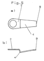
- FIGS. 2 and 3 appear angled in a Z-shape in the side view and the opposite cutting edges run towards one another towards the tip of the blade and are in turn connected to one another there by an essentially semicircular cutting edge tip 6 ′.
- the knife and in particular the blade 3 are also curved in a crescent shape.
- the blade can also have a cutting edge 6 on only one side.
- the intermediate parts 4 can also be provided with a coating which can be identical to the coating of the surfaces 1 of the blade, but can also be different from this.
- the intermediate part is coated on both sides and up to what point depends on the special application for which it is intended and on the method by which the coating is applied. In any case, the surfaces of the intermediate part, which touch other, fixed parts during the oscillating movements of the knife and thus contribute to friction or can also damage other parts, should be included be provided with an appropriate coating.
- the coating material care must be taken that the material is both friction and temperature resistant and does not become detached from the carrier material when the knife is used.
- those coating materials should preferably be selected that do not give off harmful vapors when heated due to the friction that is still present. Overheating of the knife and the coating can also be avoided by good heat dissipation by selecting a suitable knife material and a corresponding shape.
- the knives can also have other cross-sectional shapes, e.g. flat on both sides with laterally ground cutting edges.
Landscapes
- Life Sciences & Earth Sciences (AREA)
- Forests & Forestry (AREA)
- Engineering & Computer Science (AREA)
- Mechanical Engineering (AREA)
- Knives (AREA)
Applications Claiming Priority (2)
| Application Number | Priority Date | Filing Date | Title |
|---|---|---|---|
| DE3942230A DE3942230A1 (de) | 1989-12-21 | 1989-12-21 | Messer fuer oszillierenden antrieb |
| DE3942230 | 1989-12-21 |
Publications (1)
| Publication Number | Publication Date |
|---|---|
| EP0433539A1 true EP0433539A1 (fr) | 1991-06-26 |
Family
ID=6395977
Family Applications (1)
| Application Number | Title | Priority Date | Filing Date |
|---|---|---|---|
| EP90111188A Withdrawn EP0433539A1 (fr) | 1989-12-21 | 1990-06-13 | Couteau à actionnement oscillatoire |
Country Status (2)
| Country | Link |
|---|---|
| EP (1) | EP0433539A1 (fr) |
| DE (1) | DE3942230A1 (fr) |
Cited By (2)
| Publication number | Priority date | Publication date | Assignee | Title |
|---|---|---|---|---|
| EP1068937A1 (fr) * | 1999-07-10 | 2001-01-17 | C. & E. Fein Gmbh & Co. KG | Lame de coupe pour couper des bourrelets adhésifs aux vitres |
| DE10164081A1 (de) * | 2001-12-19 | 2003-07-03 | C & E Fein Gmbh & Co Kg | Oszillationswerkzeug mit Ausgleichsabschnitt |
Families Citing this family (2)
| Publication number | Priority date | Publication date | Assignee | Title |
|---|---|---|---|---|
| DE19938115A1 (de) * | 1999-08-12 | 2001-02-22 | Fein C & E | Schneidmesser |
| DE102012007489A1 (de) * | 2012-03-30 | 2013-10-02 | C. & E. Fein Gmbh | Spachtel |
Citations (3)
| Publication number | Priority date | Publication date | Assignee | Title |
|---|---|---|---|---|
| DE1245099B (de) * | 1961-09-28 | 1967-07-20 | Dixon Corp | Verfahren zur Herstellung von Verbundstoffen durch ein- oder zweiseitiges Beschichten von Metalloberflaechen mit Polytetrafluoraethylen |
| US4450205A (en) * | 1979-10-26 | 1984-05-22 | Mitsubishi Kinzoku Kabushiki Kaisha | Surface-coated blade member of super hard alloy for cutting tools and process for producing same |
| GB2185207A (en) * | 1986-01-08 | 1987-07-15 | Gerber Scient Inc | Knife blade and method for making same |
Family Cites Families (2)
| Publication number | Priority date | Publication date | Assignee | Title |
|---|---|---|---|---|
| DE1930115C3 (de) * | 1966-08-20 | 1980-05-08 | Vepa Ag, Riehen B. Basel (Schweiz) | Vorrichtung zum Wärmebehandeln von Textilbahnen mit einem Flor aus druckempfindlichen Fasern |
| DE8423004U1 (de) * | 1984-08-02 | 1984-10-31 | C. & E. Fein Gmbh & Co, 7000 Stuttgart | Schneidmesser zum durchtrennen der klebeschicht einer angeklebten scheibe |
-
1989
- 1989-12-21 DE DE3942230A patent/DE3942230A1/de not_active Ceased
-
1990
- 1990-06-13 EP EP90111188A patent/EP0433539A1/fr not_active Withdrawn
Patent Citations (3)
| Publication number | Priority date | Publication date | Assignee | Title |
|---|---|---|---|---|
| DE1245099B (de) * | 1961-09-28 | 1967-07-20 | Dixon Corp | Verfahren zur Herstellung von Verbundstoffen durch ein- oder zweiseitiges Beschichten von Metalloberflaechen mit Polytetrafluoraethylen |
| US4450205A (en) * | 1979-10-26 | 1984-05-22 | Mitsubishi Kinzoku Kabushiki Kaisha | Surface-coated blade member of super hard alloy for cutting tools and process for producing same |
| GB2185207A (en) * | 1986-01-08 | 1987-07-15 | Gerber Scient Inc | Knife blade and method for making same |
Cited By (4)
| Publication number | Priority date | Publication date | Assignee | Title |
|---|---|---|---|---|
| EP1068937A1 (fr) * | 1999-07-10 | 2001-01-17 | C. & E. Fein Gmbh & Co. KG | Lame de coupe pour couper des bourrelets adhésifs aux vitres |
| US6401342B1 (en) | 1999-07-10 | 2002-06-11 | C. & E. Fein Gmbh & Co. | Cutting knife for cutting cement beads of window panes |
| DE10164081A1 (de) * | 2001-12-19 | 2003-07-03 | C & E Fein Gmbh & Co Kg | Oszillationswerkzeug mit Ausgleichsabschnitt |
| DE10164081B4 (de) * | 2001-12-19 | 2012-01-26 | C. & E. Fein Gmbh | Oszillationswerkzeug mit Ausgleichsabschnitt |
Also Published As
| Publication number | Publication date |
|---|---|
| DE3942230A1 (de) | 1991-06-27 |
Similar Documents
| Publication | Publication Date | Title |
|---|---|---|
| EP0174427B1 (fr) | Couteau pour séparer la couche de colle d'une vitre collée | |
| EP0453906B1 (fr) | Tête de rasage, en particulier une unité de lames pour rasoir mécanique | |
| DE10138356A1 (de) | Schere, insbesondere für chirurgische Zwecke | |
| DE19618803C2 (de) | Keramische Klinge | |
| DE69417838T2 (de) | Rasiergerät | |
| DE69717286T2 (de) | Sprung- und schwingungsfreies wischblatt | |
| DE9210044U1 (de) | Rasierapparatekopf eines Naßrasierapparates | |
| EP0695607A1 (fr) | Lame de scie à os et scie à os équipée d'une telle lame de scie | |
| DE2932885A1 (de) | Rasierapparat | |
| EP1075909B1 (fr) | Lame de coupe | |
| DE102013112632A1 (de) | Sägeblatt für eine oszillierend angetriebene Säge | |
| DE10248026B4 (de) | Verfahren zur Herstellung einer Friseurschere, sowie Friseurschere | |
| DE19749561A1 (de) | Band- oder Gattermesser | |
| EP0433539A1 (fr) | Couteau à actionnement oscillatoire | |
| EP0560239A1 (fr) | Tête de rasage pour rasor mécanique | |
| EP0294617B1 (fr) | Outil de coupe | |
| EP0156395A2 (fr) | Utilisation d'un alliage forgeable à base de titane pour la fabrication d'outils de coupe comportant un tranchant et un contre-tranchant | |
| EP2021153B1 (fr) | Couteau inférieur pour une tête de coupe d'un rasoir à sec | |
| EP1002628B1 (fr) | Lame de coupe pour couper des bourrelets adhésifs aux vitres des véhicules automobiles | |
| EP0224836B1 (fr) | Barre à percussion pour broyeur à percussion ou broyeurs similaires | |
| DE3447962A1 (de) | Einhandschere aus metall, insbesondere friseurschere | |
| DE10004836C1 (de) | Rundmesser für Allesschneider und Vorrichtung zur Herstellung der Schneidezahnung | |
| DE8617670U1 (de) | Oszillierendes Trennmesser mit Verzahnung | |
| DE2850800C2 (fr) | ||
| DE2254647B2 (de) | Saegezahnglied fuer eine saegekette |
Legal Events
| Date | Code | Title | Description |
|---|---|---|---|
| PUAI | Public reference made under article 153(3) epc to a published international application that has entered the european phase |
Free format text: ORIGINAL CODE: 0009012 |
|
| AK | Designated contracting states |
Kind code of ref document: A1 Designated state(s): AT BE CH DE DK ES FR GB IT LI LU NL SE |
|
| 17P | Request for examination filed |
Effective date: 19911204 |
|
| 17Q | First examination report despatched |
Effective date: 19930217 |
|
| STAA | Information on the status of an ep patent application or granted ep patent |
Free format text: STATUS: THE APPLICATION IS DEEMED TO BE WITHDRAWN |
|
| 18D | Application deemed to be withdrawn |
Effective date: 19950105 |