EP0433559B1 - Dichtendes Absperrventil - Google Patents
Dichtendes Absperrventil Download PDFInfo
- Publication number
- EP0433559B1 EP0433559B1 EP90116860A EP90116860A EP0433559B1 EP 0433559 B1 EP0433559 B1 EP 0433559B1 EP 90116860 A EP90116860 A EP 90116860A EP 90116860 A EP90116860 A EP 90116860A EP 0433559 B1 EP0433559 B1 EP 0433559B1
- Authority
- EP
- European Patent Office
- Prior art keywords
- valve
- section
- conduit
- housing
- interface
- Prior art date
- Legal status (The legal status is an assumption and is not a legal conclusion. Google has not performed a legal analysis and makes no representation as to the accuracy of the status listed.)
- Expired - Lifetime
Links
Images

Classifications
-
- F—MECHANICAL ENGINEERING; LIGHTING; HEATING; WEAPONS; BLASTING
- F16—ENGINEERING ELEMENTS AND UNITS; GENERAL MEASURES FOR PRODUCING AND MAINTAINING EFFECTIVE FUNCTIONING OF MACHINES OR INSTALLATIONS; THERMAL INSULATION IN GENERAL
- F16L—PIPES; JOINTS OR FITTINGS FOR PIPES; SUPPORTS FOR PIPES, CABLES OR PROTECTIVE TUBING; MEANS FOR THERMAL INSULATION IN GENERAL
- F16L29/00—Joints with fluid cut-off means
- F16L29/04—Joints with fluid cut-off means with a cut-off device in each of the two pipe ends, the cut-off devices being automatically opened when the coupling is applied
-
- Y—GENERAL TAGGING OF NEW TECHNOLOGICAL DEVELOPMENTS; GENERAL TAGGING OF CROSS-SECTIONAL TECHNOLOGIES SPANNING OVER SEVERAL SECTIONS OF THE IPC; TECHNICAL SUBJECTS COVERED BY FORMER USPC CROSS-REFERENCE ART COLLECTIONS [XRACs] AND DIGESTS
- Y10—TECHNICAL SUBJECTS COVERED BY FORMER USPC
- Y10T—TECHNICAL SUBJECTS COVERED BY FORMER US CLASSIFICATION
- Y10T137/00—Fluid handling
- Y10T137/8593—Systems
- Y10T137/87917—Flow path with serial valves and/or closures
- Y10T137/87925—Separable flow path section, valve or closure in each
- Y10T137/87941—Each valve and/or closure operated by coupling motion
- Y10T137/87949—Linear motion of flow path sections operates both
- Y10T137/87957—Valves actuate each other
Definitions
- This invention relates to a shut-off valve according to the preamble of claim 1.
- sealing members are made up of rubber or other flexible material, and biasing means are provided formed of helical springs or flexible fingers.
- the valving member is a tube having a transverse opening and a disk with the rubber seal at one end. The valve spring is acting onto that disk end and needs a relative big space to be encompassed.
- the filters and purifiers have limited life spans and must be replaced periodically. These filters and purifiers have an inlet and outlet port connected to the gas line. Each inlet and outlet port has a separate connector and a separate manual shut-off valve. In order to remove and change a filter or purifier, the manual shut-off valves at each end are closed. This prevents atmospheric gas and contaminants from entering the gas line system. Additionally, some purifiers are damaged by exposure to the atmosphere. These purifiers are also isolated by means of valves prior to installation or removal. Thus, after the shut-off valves are closed, the connections on each side are then loosened and the filter or purifier is removed and replaced with a new one.
- valves and connectors have a relatively large volume inside which allows in atmospheric gases and other impurities during the replacement operation.
- Such volumes have surface areas associated with them that provide adhesion surfaces for contamination, particularly moisture.
- these impurities are present in the system.
- the present invention comprises a first tubular housing having a threaded portion and a second tubular housing having a threaded portion sized to mate with the first tubular housing.
- a disk-shaped gasket having a plurality of radially located holes is shaped to fit between the first and second tubular housing to form a seal.
- the first tubular housing has a valve sealing surface inside.
- a valving member is shaped to fit against the valve sealing surface.
- the valving member has an extension tab which engages the gasket and forces the valving member away from the sealing surface when the first and second tubular housings are connected together.
- the valving member also has a plurality of flow slots which allow gas to flow around it when it is not in contact with the valve sealing surface.
- a number of spring washers are placed between the valving member and an annular ledge such that the valving member is forced securely against the sealing surface when the first and second tubular housing are not connected and the valving member is not engaging the gasket.
- Another advantage of the present invention is that it provides a combination valve and connection assembly which is of relatively simple design, thereby providing economical assembly costs and automatic operation.
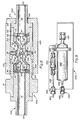
- Fig. 1 is a cross-sectional view of a first section of a valve-connection assembly of the present invention and designated by the general reference number 10.
- a stainless steel cylindrical housing 12 has a disk-shaped collar section 14. Housing 12 has a screw thread section 16.
- An internal passage 18 passes through housing 12. Internal passage 18 has a tube section 20, a reducing section 22, a restricted section 24, and an expansion section 26. The surface of the reducing section 22 is also known as the valve sealing surface.
- Housing 12 also has an integral torroidal ring 28 at the end of internal passage 18 around the exit of expansion section 26.
- a stainless steel seal member 40 is positioned within internal passage 18 such that it forms a seal with the valve sealing surface of reducing section 22.
- Poppet 40 has a rounded conical section 42 which is shaped to create a line seal when mating with the valve sealing surface 22 in housing 12.
- the conical seal section 42 is rounded to preclude jamming due to possible misalignment.
- a cylindrical extension section 44 protrudes through the restricted section 24 and the expansion section 26. Extension section 44 has a rounded tip 46.
- Poppet 40 also has four pie-shaped leg members 48 which extend upward from rounded conical section 42. Each of legs 48 has a pie-shaped tab member 50.
- a plurality of stainless steel spring washers 60 are positioned above poppet 40. In the preferred embodiment, five spring washers 60 are used.
- the spring washers 60 each have an outside diameter sized to fit within tube section 20 and an internal diameter sized to receive tabs 50 of poppet 40.
- a stainless steel press-fit collar 70 is sized to fit snugly inside passage 18.
- the outside edges 72 of collar 70 are rounded. Edges 72 form an annular ledge which one of spring washers 60 rests against.
- Collar 70 has an internal passage 74.
- Fig. 1 shows valve 10 with the spring washers 60 in an uncompressed condition.
- Fig. 2 shows a cross-sectional view of valve section 10 with the spring washers 60 in a partially compressed condition.
- the collar 70 has been press fit into passage 18, a distance such that it is flush with the top surface of housing 12.
- spring washers 60 exert approximately 158 N (35 lbf) against poppet 40 and force the poppet 40 securely against the seal face of reducing section 22.
- Fig. 3 is a cross-sectional view of the valve-connection assembly of the present invention and is designated by the general reference number 100.
- a stainless steel nut section 102 has an internal screw thread section 104 which mates with the screw thread section 16 of housing 12.
- Nut section 102 has a passage 106 which receives a stainless steel interface 110.
- Interface 110 has an internal tube section 114.
- Interface 110 has a flange section 120 which keeps interface 110 in its proper position within nut section 102.
- Interface 110 also has torroidal ring section 122.
- the ring section 122 corresponds in size and is aligned with ring section 28 of housing 12.
- Fig. 4 shows an end view of a gasket 130.
- the disk-shaped nickel gasket 130 is positioned between ring section 28 and ring section 122.
- the plurality of flow apertures 132 provide a flow path for gas.
- the central dimple 134 provides for receiving the rounded tip 46 of poppet 40.
- a tubular section 140 extends from the interface 110.
- Fig. 5 shows a top view of poppet 40.
- Each leg 48 has one of the smaller pie-shaped tabs 50.
- the tabs 50 are sized to fit within the internal diameter of spring washers 60.
- the space between the legs 48 forms a cross-shaped flow passage 150.
- Fig. 6 shows a side view of poppet 40 and Fig. 7 shows a bottom view of poppet 40.
- Fig. 8 is a cross-sectional view of a dual-sided shut-off system 300, including two valve-connection assemblies connected in end-to-end relationship.
- the components of system 300 which are the same as the valve-connection assembly 700, carry the same reference numeral distinguished by a prime designation.
- the system 300 includes a male valve-connection assembly 302 and a female valve-connection assembly 304.
- the system 300 includes a stainless steel nut section 306 which has internal threads 308 for engaging the threads of internal screw thread section 104'.
- Nut section 306 has a smooth internal surfaced cylindrical section 310 which has an internal diameter greater than the outer diameter of an internal sleeve 312.
- the sleeve 312 is similar to the sleeve 104' except that the outer surface is smooth thereby allowing the sleeve 306 to slide over it.
- the sleeve 306 has an internal protruding shoulder 314 about the terminal end of the section 312. When assembled, the shoulder 314 abuts the flange section 120' of the valve-connector assembly 304.
- the sleeve 306 advances or retracts relative to the section 104' of the valve-connector assembly 302.
- the shoulder 314 advances or retracts relative to the sleeve 312.
- the valve-connectors 302 and 304 open and close simultaneously dependent upon rotation of section 102.
- Fig. 9 shows a gas purifier and filter system and is designated by the general reference number 400.
- System 400 has a gas inlet line 402.
- Line 402 is welded to valve-connection assembly 300.
- Assembly 300 is connected to a purifier inlet tube 420 tied to a purifier 422.
- Purifier 422 is a canister which is filled with a purifying resin through a fill port 424.
- the purifier resin may be Nanochem resin.
- Purifier 422 is connected to a purifier outlet tube 426.
- the tube 426 is connected to a filter 430.
- Filter 430 is connected to a filter outlet line 432.
- Filter outlet line 432 is connected to another valve-connection assembly 300 which is connected to a gas outlet line 450.
- valve housing 12 Once the valve housing 12 has been assembled with collar 72 press fitted in proper position, the spring washers 60are preloaded as shown in Fig. 2.
- the spring washers 60 exert 158 N (35 lbf) against poppet 40 and force it against the valve sealing surface of reducing section 22 to form a seal. Gas flowing through passage 18 is shut-off.
- valve 100 automatically closes when housing 12 and nut section 102 are disconnected and automatically opens when the connection between housing 12 and nut section 102 is made. Because travel of poppet 40 is small, only approximately one turn of nut 102 is required to open or close the valve.
- the present invention is ideal for use in high purity gas systems.
- system 400 of Fig. 9 a combination purifier 422 and filter 430 is connected to a gas inlet 402 and outlet 450 via two valve-connection assemblies 100 of the present invention.
- the purifier 422 and filter 430 need replacement, the nut sections of both valves are loosened and the purifier 422 and filter 430 are removed.
- the valve-connection assemblies 100 automatically shut to prevent atmospheric contamination from entering the gas system.
- the valve-connection assemblies 100 are automatically opened.
- Prior art systems use separate manual shut-off valves and connectors. This increases the entrapment space and allows more contaminants to enter the system.
- Another advantage of the present invention is that it increases safety relative to the prior art.
- the operator may get a blast of gas, sometimes toxic, in his or her face.
- this risk is overcome because it automatically shuts off the gas flow as soon as the nut section is loosened.
- the present invention has additional features which help reduce contamination of the system.
- spring washers 60 are completely deflected. There is no space left between each of the spring washers 60. This prevents impurities such as moisture from collecting and contaminating the system.
- the collar 70 has rounded edges 72. When spring washers 60 deflect, as in Fig. 2, they pivot or roll along rounded edge 72. This results in much less wear between edge 72 and washer spring 60. The reduced friction results in greatly reducing the amount of metal particles which are introduced into the gas system.
Landscapes
- Engineering & Computer Science (AREA)
- General Engineering & Computer Science (AREA)
- Mechanical Engineering (AREA)
- Lift Valve (AREA)
Claims (10)
- Absperrventil für eine Ventilkupplungsanordnung mit folgenden Merkmalen:
eine erste Kupplungshälfte (10, 302) weist eine erste Leitung (18, 74, 74′) und
eine zweite Kupplungshälfte (110, 304) weist eine zweite Leitung (74 , 114) auf und ist zur Verbindung mit der ersten Kupplungshälfte und zur Bildung einer Abdichtung ausgebildet;
das Absperrventil besitzt eine Ventilabsperreinrichtung (22, 40, 60), die
ein Ventilglied, welches innerhalb der ersten Leitung angeordnet ist und zur Bildung einer Dichtung mit einer Abdichtoberfläche (22) in der Leitung gestaltet ist, und eine Vorspannungseinrichtung (60) aufweist, die an einer Schulter der ersten Leitung und an dem Ventilglied (40) anliegt, um das Ventilglied (40) gegen die Abdichtoberfläche (22) zu pressen, wenn die erste und zweite Kupplungshälfte (10, 110, 302, 304) nicht verbunden sind, um einen Fluidstrom durch die erste Leitung (18, 74, 74′) abzusperren,
dadurch gekennzeichnet,
daß das Absperrventil ganz aus Metall besteht,
daß das Ventilglied (40) einen Strömungskanal (150) aufweist, der an einem Abdichtabschnitt (42, 42′) endet und geöffnet wird, wenn die Kupplungshälften (10, 110, 302, 304) miteinander verbunden sind, und daß die Vorspanneinrichtung (60) mindestens einen Federring aufweist, dessen Öffnung mit dem Strömungskanal (150) verbunden ist und dessen Außendurchmesser so bemessen ist, daß er in die erste Leitung (18) entlang eines relativ kleinen Raumes (20) paßt. - Ventil nach Anspruch 1,
dadurch gekennzeichnet,
daß die erste Kupplungshälfte eine abgerundete Kante (72) aufweist, auf welcher eine Ringoberfläche des Federrings (60) aufliegt, damit sich die ringförmige Oberfläche über die abgerundete Kante (72) abwälzen kann, wenn der Federring (60) ausgelenkt wird. - Ventil nach Anspruch 1 oder 2,
dadurch gekennzeichnet,
daß die Vorspannungseinrichtung (60) einen Stapel von Federringen (60) aufweist, die maximal abgelenkt werden, wenn die erste und zweite Kupplungshälfte miteinander verbunden sind. - Ventil nach Anspruch 1, 2 oder 3,
dadurch gekennzeichnet,
daß das Ventilglied (40) ein Sitzventilglied ist und passend zur Öffnung des Federringes (60) bemessen (50) ist. - Ventil nach einem der Ansprüche 1 bis 4,
dadurch gekennzeichnet,
daß der Strömungskanal (150) durch Schlitze gebildet wird, welche den Fluidstrom durch die Öffnung der Federringe (60) leiten, wenn das Ventilglied (40) nicht in Kontakt mit der Abdichtoberfläche (22) steht. - Ventil nach einem der Ansprüche 1 bis 5,
dadurch gekennzeichnet,
daß eine Zwischendichtung (130) bemessen ist, um zwischen die erste Kupplungshälfte (10, 302) und die zweite Kupplungshälfte (110, 304) zu passen und die erste Leitung (18, 74, 74′) an der zweiten Leitung (74′, 114) hermetisch abzudichten. - Ventil nach Anspruch 6,
dadurch gekennzeichnet,
daß die erste und zweite Kupplungshälfte jeweils ein rohrförmiges Gehäuse (12, 110) umfassen und
daß eine Befestigungseinrichtung (102) mit dem ersten Gehäuse (18, 12, 74′) und mit dem zweiten Gehäuse (110) verbunden ist, um die erste (18, 74, 74′) und die zweite (74′, 114) Leitung miteinander zu verbinden, und
daß das Ventilglied (40) einen Verlängerungsabschnitt (44) aufweist, der um ein Stück von der Abdichtoberfläche (22) vorsteht, um an der Zwischendichtung (130) anzuliegenen, wenn die Befestigungseinrichtung (102) das erste und das zweite Gehäuse miteinander verbindet. - Ventil nach Anspruch 7,
dadurch gekennzeichnet,
daß die Befestigungseinrichtung (102) einen ersten, auf dem ersten Gehäuse (12) angeordneten Verschraubungsabschnitt (16) und einen zweiten, mit dem zweiten Gehäuse (110) verbundenen (120, 120′) Verschraubungsabschnitt (104) aufweist. - Ventil nach Anspruch 7 oder 8,
dadurch gekennzeichnet,
daß das erste und zweite Gehäuse jeweils eine Abdichtoberfläche (22′) und einen Abdichtabschnitt (42′) aufweisen,
daß jeder Abdichtabschnitt (42′) einen Verlängerungsabschnitt (44′) umfaßt, der sich zur Zwischendichtung (130′) erstreckt, und
daß die Befestigungseinrichtung (102) zur Verschiebung der Verlängerungsabschnitte (44′) in Anlage an der Zwischendichtung (130) dient, wenn das Absperrventil zu öffnen ist, und außer Eingriff mit der Zwischendichtung steht, wenn die Vorspannungseinrichtungen (60′) die Abdichtungsabschnitte (42′) auf ihre jeweiligen Abdichtoberflächen (22′) verschieben. - Ventil nach Anspruch 8 oder 9,
dadurch gekennzeichnet,
daß die Befestigungseinrichtung (102) einen ersten Verschraubungsabschnitt (308) und eine Schulter (314) aufweist, die an dem zweiten Gehäuse anliegt.
Applications Claiming Priority (2)
| Application Number | Priority Date | Filing Date | Title |
|---|---|---|---|
| US453407 | 1982-12-27 | ||
| US07/453,407 US4971110A (en) | 1989-12-19 | 1989-12-19 | Face seal shut-off valve |
Publications (2)
| Publication Number | Publication Date |
|---|---|
| EP0433559A1 EP0433559A1 (de) | 1991-06-26 |
| EP0433559B1 true EP0433559B1 (de) | 1993-04-14 |
Family
ID=23800453
Family Applications (1)
| Application Number | Title | Priority Date | Filing Date |
|---|---|---|---|
| EP90116860A Expired - Lifetime EP0433559B1 (de) | 1989-12-19 | 1990-09-03 | Dichtendes Absperrventil |
Country Status (3)
| Country | Link |
|---|---|
| US (1) | US4971110A (de) |
| EP (1) | EP0433559B1 (de) |
| DE (1) | DE69001352T2 (de) |
Families Citing this family (7)
| Publication number | Priority date | Publication date | Assignee | Title |
|---|---|---|---|---|
| US5558688A (en) * | 1994-07-14 | 1996-09-24 | Semi-Gas Systems, Inc. | Block filter-purifier |
| US5902551A (en) * | 1995-01-13 | 1999-05-11 | Semi-Gas Systems, Inc. | Process gas docking station with point-of-use filter for receiving removable purifier cartridges |
| US6149718A (en) * | 1998-10-16 | 2000-11-21 | Mott Mettallurgical Corporation | Contamination control system |
| JP4378647B2 (ja) * | 2006-09-20 | 2009-12-09 | Smc株式会社 | 管継手 |
| EP1989946A1 (de) | 2007-05-11 | 2008-11-12 | Rauchless Inc. | Rauchartikel, Ladevorrichtung und Verwendungsverfahren |
| GB201012154D0 (en) * | 2010-07-20 | 2010-09-01 | Linde Ag | Closure device |
| CN102297299A (zh) * | 2011-08-24 | 2011-12-28 | 山东煤田地质机械厂 | 防泄漏接头 |
Family Cites Families (9)
| Publication number | Priority date | Publication date | Assignee | Title |
|---|---|---|---|---|
| US1345571A (en) * | 1917-02-07 | 1920-07-06 | Isko Company | Pipe-coupling |
| FR566513A (fr) * | 1923-05-19 | 1924-02-15 | Perfectionnements aux joints combinés avec une soupape pour tubes, tuyaux et organes analogues | |
| US2428638A (en) * | 1945-05-21 | 1947-10-07 | Albert T Scheiwer | Coupling |
| FR1142146A (fr) * | 1956-02-22 | 1957-09-13 | Dispositif avec soupape pour raccord de conduite pour fluide obturant automatiquement ce raccord dès que l'on démonte l'organe vissé sur lui | |
| US2931668A (en) * | 1956-04-30 | 1960-04-05 | Bastian Blessing Co | Coupling |
| US3129919A (en) * | 1961-09-08 | 1964-04-21 | Band It Company | Valved quick coupler |
| US4063708A (en) * | 1976-07-08 | 1977-12-20 | The Gorman-Rupp Company | Quick disconnect device for flexible tubes |
| EP0034312B1 (de) * | 1980-02-14 | 1985-01-16 | Aeroquip GmbH | Auch unter Druck kuppelbare Schnellverschlusskupplung |
| US4509554A (en) * | 1982-11-08 | 1985-04-09 | Failla William G | High and low pressure, quick-disconnect coupling |
-
1989
- 1989-12-19 US US07/453,407 patent/US4971110A/en not_active Expired - Lifetime
-
1990
- 1990-09-03 EP EP90116860A patent/EP0433559B1/de not_active Expired - Lifetime
- 1990-09-03 DE DE90116860T patent/DE69001352T2/de not_active Expired - Fee Related
Also Published As
| Publication number | Publication date |
|---|---|
| EP0433559A1 (de) | 1991-06-26 |
| DE69001352T2 (de) | 1993-10-28 |
| DE69001352D1 (de) | 1993-05-19 |
| US4971110A (en) | 1990-11-20 |
Similar Documents
| Publication | Publication Date | Title |
|---|---|---|
| EP0137636B1 (de) | Filtergerät | |
| EP0322406B1 (de) | Balgdichtungsventil | |
| EP0244185B1 (de) | Faltenbalgventil | |
| US5360036A (en) | Vented ball valve with lock-out ring | |
| US5848605A (en) | Check valve | |
| US4529515A (en) | Valve | |
| CA1293495C (en) | In-line repairable top entry ball valve | |
| US3761052A (en) | Flow plugger valve | |
| US4322290A (en) | Filter assembly | |
| EP1114266B1 (de) | Schaltventil | |
| US4421298A (en) | Y Pattern valve | |
| US4818397A (en) | Shut-off valve seal | |
| US2845085A (en) | Separable, yieldable mounting for valves | |
| EP0123855B1 (de) | Auslassvorsatz zum Befestigen am Ausgang eines Gasbehälters | |
| EP0408177A1 (de) | Rückschlagventilpatronen mit kontrollierbarer Druckabdichtung | |
| US4028254A (en) | Fluid filter | |
| EP0433559B1 (de) | Dichtendes Absperrventil | |
| EP3143471A1 (de) | Verfahren und vorrichtung für zugang auf und ausrichtung von dichtscheiben | |
| US4557302A (en) | Retainer ring for the spout of a fluid dispensing nozzle | |
| CA1291741C (en) | Valve with compressible valve stem and valve body seals | |
| US6592758B2 (en) | Filter element for a liquid-state process stream | |
| US3425660A (en) | Faucet valve | |
| US5242581A (en) | Shut-off valve | |
| US20060096908A1 (en) | Device for filtering fluids that are conveyed under a high presure | |
| US4501295A (en) | Transfer valve |
Legal Events
| Date | Code | Title | Description |
|---|---|---|---|
| PUAI | Public reference made under article 153(3) epc to a published international application that has entered the european phase |
Free format text: ORIGINAL CODE: 0009012 |
|
| AK | Designated contracting states |
Kind code of ref document: A1 Designated state(s): DE GB |
|
| 17P | Request for examination filed |
Effective date: 19910705 |
|
| 17Q | First examination report despatched |
Effective date: 19911031 |
|
| GRAA | (expected) grant |
Free format text: ORIGINAL CODE: 0009210 |
|
| AK | Designated contracting states |
Kind code of ref document: B1 Designated state(s): DE GB |
|
| REF | Corresponds to: |
Ref document number: 69001352 Country of ref document: DE Date of ref document: 19930519 |
|
| PLBE | No opposition filed within time limit |
Free format text: ORIGINAL CODE: 0009261 |
|
| STAA | Information on the status of an ep patent application or granted ep patent |
Free format text: STATUS: NO OPPOSITION FILED WITHIN TIME LIMIT |
|
| 26N | No opposition filed | ||
| REG | Reference to a national code |
Ref country code: GB Ref legal event code: IF02 |
|
| PGFP | Annual fee paid to national office [announced via postgrant information from national office to epo] |
Ref country code: GB Payment date: 20030903 Year of fee payment: 14 |
|
| PGFP | Annual fee paid to national office [announced via postgrant information from national office to epo] |
Ref country code: DE Payment date: 20030911 Year of fee payment: 14 |
|
| PG25 | Lapsed in a contracting state [announced via postgrant information from national office to epo] |
Ref country code: GB Free format text: LAPSE BECAUSE OF NON-PAYMENT OF DUE FEES Effective date: 20040903 |
|
| PG25 | Lapsed in a contracting state [announced via postgrant information from national office to epo] |
Ref country code: DE Free format text: LAPSE BECAUSE OF NON-PAYMENT OF DUE FEES Effective date: 20050401 |
|
| GBPC | Gb: european patent ceased through non-payment of renewal fee |
Effective date: 20040903 |