EP0433579B1 - Procédé et appareillage pour refroidir du gaz brut d'oxydation partielle - Google Patents
Procédé et appareillage pour refroidir du gaz brut d'oxydation partielle Download PDFInfo
- Publication number
- EP0433579B1 EP0433579B1 EP90118772A EP90118772A EP0433579B1 EP 0433579 B1 EP0433579 B1 EP 0433579B1 EP 90118772 A EP90118772 A EP 90118772A EP 90118772 A EP90118772 A EP 90118772A EP 0433579 B1 EP0433579 B1 EP 0433579B1
- Authority
- EP
- European Patent Office
- Prior art keywords
- cooling fluid
- tubes
- gas duct
- crude gas
- internals
- Prior art date
- Legal status (The legal status is an assumption and is not a legal conclusion. Google has not performed a legal analysis and makes no representation as to the accuracy of the status listed.)
- Expired - Lifetime
Links
Images

Classifications
-
- C—CHEMISTRY; METALLURGY
- C01—INORGANIC CHEMISTRY
- C01B—NON-METALLIC ELEMENTS; COMPOUNDS THEREOF; METALLOIDS OR COMPOUNDS THEREOF NOT COVERED BY SUBCLASS C01C
- C01B3/00—Hydrogen; Gaseous mixtures containing hydrogen; Separation of hydrogen from mixtures containing it; Purification of hydrogen; Reversible storage of hydrogen
- C01B3/02—Production of hydrogen; Production of gaseous mixtures containing hydrogen
-
- C—CHEMISTRY; METALLURGY
- C10—PETROLEUM, GAS OR COKE INDUSTRIES; TECHNICAL GASES CONTAINING CARBON MONOXIDE; FUELS; LUBRICANTS; PEAT
- C10J—PRODUCTION OF PRODUCER GAS, WATER-GAS, SYNTHESIS GAS FROM SOLID CARBONACEOUS MATERIAL, OR MIXTURES CONTAINING THESE GASES; CARBURETTING AIR OR OTHER GASES
- C10J3/00—Production of combustible gases containing carbon monoxide from solid carbonaceous fuels
- C10J3/46—Gasification of granular or pulverulent flues in suspension
- C10J3/466—Entrained flow processes
-
- C—CHEMISTRY; METALLURGY
- C10—PETROLEUM, GAS OR COKE INDUSTRIES; TECHNICAL GASES CONTAINING CARBON MONOXIDE; FUELS; LUBRICANTS; PEAT
- C10J—PRODUCTION OF PRODUCER GAS, WATER-GAS, SYNTHESIS GAS FROM SOLID CARBONACEOUS MATERIAL, OR MIXTURES CONTAINING THESE GASES; CARBURETTING AIR OR OTHER GASES
- C10J3/00—Production of combustible gases containing carbon monoxide from solid carbonaceous fuels
- C10J3/72—Other features
- C10J3/82—Gas withdrawal means
- C10J3/84—Gas withdrawal means with means for removing dust or tar from the gas
-
- C—CHEMISTRY; METALLURGY
- C10—PETROLEUM, GAS OR COKE INDUSTRIES; TECHNICAL GASES CONTAINING CARBON MONOXIDE; FUELS; LUBRICANTS; PEAT
- C10K—PURIFYING OR MODIFYING THE CHEMICAL COMPOSITION OF COMBUSTIBLE GASES CONTAINING CARBON MONOXIDE
- C10K1/00—Purifying combustible gases containing carbon monoxide
- C10K1/04—Purifying combustible gases containing carbon monoxide by cooling to condense non-gaseous materials
-
- C—CHEMISTRY; METALLURGY
- C10—PETROLEUM, GAS OR COKE INDUSTRIES; TECHNICAL GASES CONTAINING CARBON MONOXIDE; FUELS; LUBRICANTS; PEAT
- C10J—PRODUCTION OF PRODUCER GAS, WATER-GAS, SYNTHESIS GAS FROM SOLID CARBONACEOUS MATERIAL, OR MIXTURES CONTAINING THESE GASES; CARBURETTING AIR OR OTHER GASES
- C10J2300/00—Details of gasification processes
- C10J2300/09—Details of the feed, e.g. feeding of spent catalyst, inert gas or halogens
- C10J2300/0953—Gasifying agents
- C10J2300/0956—Air or oxygen enriched air
-
- C—CHEMISTRY; METALLURGY
- C10—PETROLEUM, GAS OR COKE INDUSTRIES; TECHNICAL GASES CONTAINING CARBON MONOXIDE; FUELS; LUBRICANTS; PEAT
- C10J—PRODUCTION OF PRODUCER GAS, WATER-GAS, SYNTHESIS GAS FROM SOLID CARBONACEOUS MATERIAL, OR MIXTURES CONTAINING THESE GASES; CARBURETTING AIR OR OTHER GASES
- C10J2300/00—Details of gasification processes
- C10J2300/09—Details of the feed, e.g. feeding of spent catalyst, inert gas or halogens
- C10J2300/0953—Gasifying agents
- C10J2300/0959—Oxygen
-
- C—CHEMISTRY; METALLURGY
- C10—PETROLEUM, GAS OR COKE INDUSTRIES; TECHNICAL GASES CONTAINING CARBON MONOXIDE; FUELS; LUBRICANTS; PEAT
- C10J—PRODUCTION OF PRODUCER GAS, WATER-GAS, SYNTHESIS GAS FROM SOLID CARBONACEOUS MATERIAL, OR MIXTURES CONTAINING THESE GASES; CARBURETTING AIR OR OTHER GASES
- C10J2300/00—Details of gasification processes
- C10J2300/18—Details of the gasification process, e.g. loops, autothermal operation
- C10J2300/1846—Partial oxidation, i.e. injection of air or oxygen only
Definitions
- the invention relates to a method and a device for cooling partial oxidation raw gas, which is obtained by gasification (partial oxidation) of fine-grained to dusty fuels in an entrained flow gasifier in the presence of oxygen and / or air and water vapor at pressures up to 100 bar and temperatures above the slag melting point , the gas to be cooled being quenched with a gaseous or vaporous cooling fluid
- the gasification temperatures are in the range of approx. 1700 ° C to approx. 2000 ° C.
- the raw gas channel which consists of the reactor shaft of the gasification reactor located above the burner level as well as the radiation cooler immediately adjacent to it, it cools down through chemical reactions as well as heat emission to the cooled walls of the raw gas channel.
- the final temperatures of the partial oxidation tube gas are between 800 ° C and 1600 ° C.
- the first-mentioned goal is a penetration which is as strong as possible and thus intensive mixing of the two gas streams or a long mixing section necessary.
- EP-A-0 284 762 also describes a quench cooler arranged below a gasification reactor for cooling synthesis gas, and spray nozzles protrude into the interior thereof. About these spray nozzles water is injected into the hot gas stream in such an amount that the water evaporates almost completely and the gas is simultaneously cooled to about 300 to 600 ° C.
- the invention is therefore based on the object of further developing the cooling method of the type mentioned in such a way that both the cooling of the peripheral zones and the flow core of the raw gas stream takes place in an optimal manner in which only a relatively short mixing distance is required and thus a lower overall height of the Gasification plant can be achieved with correspondingly low construction costs.
- the method of the type mentioned at the outset which is used to achieve this object is characterized in accordance with the invention in that the cooling fluid is partially supplied via pipes which are aligned in and / or on radial internals in the raw gas duct are arranged, is introduced, while the supply of the remaining part of the cooling fluid from the jacket of the raw gas channel takes place via inlet openings arranged between the radial internals and / or behind them in the gas flow direction, the partial flows of the cooling fluid being directed radially to the center axis of the raw gas channel.
- the raw gas channel is to be understood to mean that part of the gasification plant which begins just above the burner level of the gasification reactor and extends over the entire reactor shaft connected to it and the radiation cooler.
- the raw gas channel has such radial internals (bulkheads) which are cooled with water and have a protective layer on their surface have fireproof material.
- radial internals are said to improve the indirect cooling of the raw gas flow and thus to reduce the overall height of the gasification system.
- the radial internals themselves have no facilities for introducing a cooling fluid into the raw gas stream.
- the inventive design of the radial internals is therefore not anticipated by the two earlier patent applications mentioned above.
- the amount of cooling fluid introduced in this way can be regulated depending on the raw gas temperature above the raw gas channel.
- This part of the cooling fluid cools the hot and fast flow core of the raw gas flow, which is difficult to reach from the outside, while the other part of the cooling fluid, which is introduced from the jacket of the raw gas channel, cools the gas flowing in the edge region between the radial internals and at the same time forms a protective veil for the jacket of the raw gas channel.
- the maximum amount of cooling fluid that can be supplied via the radial internals results from the number of radial internals, the number of pipes fitted in or on these internals and their outlet diameter and the flow rate of the cooling fluid within the above volume proportion.
- the number of tubes arranged in or on the radial internals can be in the range between 1 and 10, preferably between 2 and 4. If a plurality of tubes are arranged in or on the radial internals, then it will be appropriate to provide the corresponding number of tubes between two radial internals, which are arranged one above the other, so that the introduction of the cooling fluid both via the radial internals and from the jacket of the Raw gas canals can be distributed in several levels as evenly as possible over the entire length of the raw gas canal.
- the outlet openings or nozzles of all tubes are designed so that all partial flows of the cooling fluid entering the raw gas flow are directed radially to the central axis.
- the individual partial flows of the cooling fluid can be introduced in or against the direction of flow of the upward raw gas flow.
- the boiler tubes of the radiation cooler which are also not shown in the figure, are arranged in the jacket 2.
- the jacket 2 is provided with a fire-resistant and reaction-resistant lining, which was also not shown. It was not necessary to reproduce these structural details in the design of the casing 2 because they correspond to the state of the art and are not the subject of the present invention.
- the radial internals 3 protrude into the raw gas duct 1, which are also provided with water cooling and on the outside with a fire-resistant and reaction-resistant protective layer.
- the width of the radial internals 3 is dimensioned such that a sufficiently large free space is still available in the central region of the raw gas channel 1, in which the flow of the hot partial oxidation raw gas can flow unhindered from bottom to top in the direction of arrows 11.
- the convection cooler which is not shown in the illustration and is provided with fittings, or a combined cooler-heat exchanger.
- the partial oxidation raw gas it is also possible for the partial oxidation raw gas to be deflected before it enters these devices, so that the gas flows through these devices from top to bottom.
- the tubes 5 and in the radial baffles 3 arranged the pipes 6 through which part of the cooling fluid is introduced into the raw gas channel 1.
- the cooling fluid introduced in this way mixes with the flow core of the ascending raw gas stream and ensures sufficient cooling there.
- the tubes 6 are only arranged in one plane in the figure. In practice, of course, they can be arranged in several levels one above the other and thus extend over the entire height of the radial internals 3. However, the tubes 6 are preferably arranged in the upper third of the radial internals 3.
- annular gaps can also be arranged in the jacket 2 at this point.
- the pipes 10 open into the raw gas duct 1, which are also embedded in the jacket 2 and can be arranged in several planes. The cooling fluid emerges from these tubes 10 in the direction of the arrows 9 and cools the raw gas flowing upward between the radial internals 3.
- this mixing and calming space 13 is located in front of the constriction 12 or the devices provided with internals (convection cooler or the like). According to the invention, this mixing and calming space 13 should have a height which corresponds to the 0.2 to 5 times, preferably 0.2 to 2 times, the diameter of the raw gas channel 1 corresponds.
- the amount of cooling fluid which is introduced via the pipes 5 and 6 can be regulated as a function of the raw gas temperature above the raw gas duct 1.
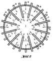
- FIG. 2 shows the radial arrangement of the internals 3 clearly.
- the arrows in FIG. 2 clearly show that all partial flows of the cooling fluid entering the raw gas channel 1 are directed radially to the center axis of the raw gas channel 1.
- the method according to the invention can of course also be used if the gasification system is designed in such a way that the gas to be cooled enters the raw gas channel from above and flows through it from top to bottom.
Landscapes
- Chemical & Material Sciences (AREA)
- Engineering & Computer Science (AREA)
- Combustion & Propulsion (AREA)
- Organic Chemistry (AREA)
- Oil, Petroleum & Natural Gas (AREA)
- General Chemical & Material Sciences (AREA)
- Chemical Kinetics & Catalysis (AREA)
- Inorganic Chemistry (AREA)
- Industrial Gases (AREA)
- Hydrogen, Water And Hydrids (AREA)
- Physical Or Chemical Processes And Apparatus (AREA)
- Heat-Exchange Devices With Radiators And Conduit Assemblies (AREA)
- Devices And Processes Conducted In The Presence Of Fluids And Solid Particles (AREA)
Claims (7)
- Procédé pour le refroidissement de gaz brut d'oxydation partielle qui est obtenu par gazéification (oxydation partielle) de combustibles allant des grains fins aux poussières dans un gazéificateur à flux en présence d'oxygène et/ou d'air, ainsi que de vapeur d'eau, sous des pressions allant jusqu'à 100 bars et à des températures supérieures au point de fusion des scories, le gaz à refroidir étant soumis à un refroidissement brusque par un fluide de refroidissement gazeux ou à l'état de vapeur, caractérisé en ce que le fluide de refroidissement est admis partiellement par des tubes qui sont installés alignés dans et/ou sur des chicanes radiales dans le conduit de gaz brut, tandis que l'alimentation de la partie restante du fluide de refroidissement s'effectue à partir de l'enveloppe du conduit de gaz brut par l'intermédiaire d'orifices d'entrée installés entre les chicanes radiales et/ou, dans le sens d'écoulement du gaz, en aval de celles-ci, les courants partiels du fluide de refroidissement étant orientés radialement vers l'axe central du conduit de gaz brut.
- Procédé suivant la revendication 1, caractérisé en ce que l'admission des courants partiels du fluide de refroidissement s'effectue dans un ou plusieurs plans, la position de ces plans pouvant s'étendre sur la totalité de la hauteur du conduit de gaz brut.
- Procédé suivant les revendications 1 et 2, caractérisé en ce que la quantité du fluide de refroidissement qui est admise par l'intermédiaire des tubes installés dans ou sur les chicanes radiales est réglée en fonction de la température du gaz brut au-dessus du conduit de gaz brut, cette quantité s'élevant au moins à 40 % en volume de la totalité du fluide de refroidissement nécessaire.
- Dispositif pour l'exécution du procédé suivant les revendications 1 à 3, caractérisé en ce que, dans le conduit de gaz brut (1) sont installées des chicanes radiales (3) dans et/ou sur lesquelles sont prévus des tubes (5; 6) pour l'admission du fluide de refroidissement et, qu'en outre, dans l'enveloppe (2) du conduit de gaz de refroidissement (1), sont fichés des tubes (8; 10) pour l'admission du fluide de refroidissement, les tubes (8) s'ouvrant dans le conduit de gaz brut (1) au-dessus des chicanes radiales (3) et les tubes (10) s'ouvrant dans la zone comprise entre les chicanes radiales (3).
- Dispositif suivant la revendication 4, caractérisé en ce que les tubes (5; 6; 8; 10) sont installés dans plusieurs plans superposés.
- Dispositif suivant les revendications 4 et 5, caractérisé en ce que le nombre des tubes (5; 6) qui sont prévus par chicane radiale (3) est compris entre 1 et 10, de préférence entre 2 et 4.
- Dispositif suivant les revendications 4 à 6, caractérisé en ce qu'au-dessus des tubes (8) est prévue dans le conduit de gaz brut (1), une chambre de mélange et de stabilisation (13) dont la hauteur correspond à 0,2 à 5 fois, de préférence 0,2 à 2 fois, le diamètre du conduit de gaz brut (1).
Applications Claiming Priority (2)
| Application Number | Priority Date | Filing Date | Title |
|---|---|---|---|
| DE3938223A DE3938223A1 (de) | 1989-11-17 | 1989-11-17 | Verfahren und vorrichtung zur kuehlung von partialoxidationsrohgas |
| DE3938223 | 1989-11-17 |
Publications (2)
| Publication Number | Publication Date |
|---|---|
| EP0433579A1 EP0433579A1 (fr) | 1991-06-26 |
| EP0433579B1 true EP0433579B1 (fr) | 1992-12-09 |
Family
ID=6393713
Family Applications (1)
| Application Number | Title | Priority Date | Filing Date |
|---|---|---|---|
| EP90118772A Expired - Lifetime EP0433579B1 (fr) | 1989-11-17 | 1990-09-29 | Procédé et appareillage pour refroidir du gaz brut d'oxydation partielle |
Country Status (7)
| Country | Link |
|---|---|
| EP (1) | EP0433579B1 (fr) |
| CN (1) | CN1027177C (fr) |
| DE (2) | DE3938223A1 (fr) |
| DK (1) | DK0433579T3 (fr) |
| ES (1) | ES2036879T3 (fr) |
| PL (1) | PL164274B1 (fr) |
| ZA (1) | ZA907595B (fr) |
Families Citing this family (3)
| Publication number | Priority date | Publication date | Assignee | Title |
|---|---|---|---|---|
| DE19601323A1 (de) * | 1996-01-16 | 1997-07-17 | Atzger Juergen | Vorrichtung zur Abgaskühlung in Verdampfungskühlern |
| CN103113918A (zh) * | 2013-01-30 | 2013-05-22 | 吴江市新金城不锈钢制品有限公司 | 水煤气发生炉 |
| CN103205277A (zh) * | 2013-01-30 | 2013-07-17 | 吴江市新金城不锈钢制品有限公司 | 微型煤气发生炉 |
Family Cites Families (4)
| Publication number | Priority date | Publication date | Assignee | Title |
|---|---|---|---|---|
| NL178134C (nl) * | 1974-06-17 | 1986-02-03 | Shell Int Research | Werkwijze en inrichting voor het behandelen van een heet produktgas. |
| DE3601786C2 (de) * | 1986-01-22 | 1996-03-07 | Krupp Koppers Gmbh | Einrichtung zur Abkühlung des aus einem unter erhöhtem Druck betriebenen Vergasungsreaktor austretenden heißen Produktionsgases |
| DE3711314A1 (de) * | 1987-04-03 | 1988-10-13 | Babcock Werke Ag | Vorrichtung zum kuehlen eines synthesegases in einem quenchkuehler |
| DE3809313A1 (de) * | 1988-03-19 | 1989-10-05 | Krupp Koppers Gmbh | Verfahren und vorrichtung zum kuehlen von partialoxidationsgas |
-
1989
- 1989-11-17 DE DE3938223A patent/DE3938223A1/de not_active Withdrawn
-
1990
- 1990-09-24 ZA ZA907595A patent/ZA907595B/xx unknown
- 1990-09-29 DK DK90118772.4T patent/DK0433579T3/da active
- 1990-09-29 EP EP90118772A patent/EP0433579B1/fr not_active Expired - Lifetime
- 1990-09-29 DE DE9090118772T patent/DE59000575D1/de not_active Expired - Fee Related
- 1990-09-29 ES ES199090118772T patent/ES2036879T3/es not_active Expired - Lifetime
- 1990-11-01 CN CN90108780A patent/CN1027177C/zh not_active Expired - Fee Related
- 1990-11-08 PL PL90287682A patent/PL164274B1/pl unknown
Also Published As
| Publication number | Publication date |
|---|---|
| DE59000575D1 (de) | 1993-01-21 |
| PL164274B1 (pl) | 1994-07-29 |
| CN1051752A (zh) | 1991-05-29 |
| DK0433579T3 (da) | 1993-04-13 |
| CN1027177C (zh) | 1994-12-28 |
| ZA907595B (en) | 1991-07-31 |
| PL287682A1 (en) | 1991-11-04 |
| DE3938223A1 (de) | 1991-05-23 |
| EP0433579A1 (fr) | 1991-06-26 |
| ES2036879T3 (es) | 1993-06-01 |
Similar Documents
| Publication | Publication Date | Title |
|---|---|---|
| EP0616023B1 (fr) | Appareil de gazéification pour la gazéification sous pression de combustibles finement divisés | |
| DE2425962C3 (de) | Gasgenerator für die Vergasung feinzerteilter Brennstoffe | |
| EP0341436B1 (fr) | Procédé et dispositif pour refroidir un courant de gaz chaud contenant des particules collantes ou en fusion | |
| EP0284762B1 (fr) | Appareil pour refroidir un gaz de synthèse dans un refroidisseur à trempe | |
| DE69617839T2 (de) | Kessel und Ofen zur Rückgewinnung im Kraftverfahren | |
| DE2940933A1 (de) | Loeschring- und tauchrohrbaugruppe fuer einen reaktionsbehaelter | |
| EP0429942B1 (fr) | Appareil pour l'échange d'une matière entre un courant gazeux chaud et un liquide | |
| EP0616022B1 (fr) | Procédé pour la gazéification sous pression de combustibles finement divisés | |
| DE2610279A1 (de) | Verfahren zum verhindern der bildung von koksablagerungen bei einem wirbelschichtreaktor | |
| DE3601786A1 (de) | Einrichtung zur abkuehlung des aus einem unter erhoehtem druck betriebenen vergasungsreaktor austretenden heissen produktionsgases | |
| EP0686250B1 (fr) | Dispositif et procede permettant de bruler des constituants oxydables dans un gaz porteur a epurer | |
| EP0433579B1 (fr) | Procédé et appareillage pour refroidir du gaz brut d'oxydation partielle | |
| EP0662506B1 (fr) | Procédé et appareillage pour refroidir du gaz brut d'oxydation partielle | |
| DE2836345C2 (de) | Anlage zur Rußherstellung | |
| DE3808729A1 (de) | Verfahren und vorrichtung zur abkuehlung des aus einem vergasungsreaktor austretenden heissen produktgases | |
| DE3913731A1 (de) | Waermetauscher zum kuehlen von spaltgas | |
| DE2913748C2 (de) | Rohrbündelwärmetauscher zum Kühlen schlackenhaltiger Heißgase der Kohlevergasung | |
| DE3538515C2 (fr) | ||
| EP0716138B1 (fr) | Installation pour la gazéiffication sous pression de combustibles finement divisés afine de produire un gaz | |
| DE202016006668U1 (de) | Vorrichtung zur Kühlung und Reinigung eines Feststoffe enthaltenden Heißgasstromes | |
| DE2459281A1 (de) | Wirbelbett-feuerung | |
| DE931615C (de) | Verfahren zum Kuehlen der heissen, den Russofen verlassenden, Russ suspendiert enthaltenden Gase | |
| EP0913363A1 (fr) | Procédé et appareil pour la transformation thermique de déchets | |
| DE3111913A1 (de) | Verfahren und analge zur russherstellung | |
| DE2428549C3 (de) | Plasmaerhitzter chemischer Reaktor zum Behandeln von dispersen Materialien |
Legal Events
| Date | Code | Title | Description |
|---|---|---|---|
| PUAI | Public reference made under article 153(3) epc to a published international application that has entered the european phase |
Free format text: ORIGINAL CODE: 0009012 |
|
| AK | Designated contracting states |
Kind code of ref document: A1 Designated state(s): DE DK ES GB NL |
|
| 17P | Request for examination filed |
Effective date: 19910522 |
|
| 17Q | First examination report despatched |
Effective date: 19920206 |
|
| GRAA | (expected) grant |
Free format text: ORIGINAL CODE: 0009210 |
|
| AK | Designated contracting states |
Kind code of ref document: B1 Designated state(s): DE DK ES GB NL |
|
| GBT | Gb: translation of ep patent filed (gb section 77(6)(a)/1977) |
Effective date: 19921208 |
|
| REF | Corresponds to: |
Ref document number: 59000575 Country of ref document: DE Date of ref document: 19930121 |
|
| REG | Reference to a national code |
Ref country code: DK Ref legal event code: T3 |
|
| REG | Reference to a national code |
Ref country code: ES Ref legal event code: FG2A Ref document number: 2036879 Country of ref document: ES Kind code of ref document: T3 |
|
| PLBE | No opposition filed within time limit |
Free format text: ORIGINAL CODE: 0009261 |
|
| STAA | Information on the status of an ep patent application or granted ep patent |
Free format text: STATUS: NO OPPOSITION FILED WITHIN TIME LIMIT |
|
| 26N | No opposition filed | ||
| PGFP | Annual fee paid to national office [announced via postgrant information from national office to epo] |
Ref country code: GB Payment date: 19980814 Year of fee payment: 9 |
|
| PGFP | Annual fee paid to national office [announced via postgrant information from national office to epo] |
Ref country code: DE Payment date: 19980821 Year of fee payment: 9 |
|
| PGFP | Annual fee paid to national office [announced via postgrant information from national office to epo] |
Ref country code: DK Payment date: 19980824 Year of fee payment: 9 |
|
| PGFP | Annual fee paid to national office [announced via postgrant information from national office to epo] |
Ref country code: NL Payment date: 19980827 Year of fee payment: 9 |
|
| PGFP | Annual fee paid to national office [announced via postgrant information from national office to epo] |
Ref country code: ES Payment date: 19980925 Year of fee payment: 9 |
|
| PG25 | Lapsed in a contracting state [announced via postgrant information from national office to epo] |
Ref country code: GB Free format text: LAPSE BECAUSE OF NON-PAYMENT OF DUE FEES Effective date: 19990929 Ref country code: DK Free format text: LAPSE BECAUSE OF NON-PAYMENT OF DUE FEES Effective date: 19990929 |
|
| PG25 | Lapsed in a contracting state [announced via postgrant information from national office to epo] |
Ref country code: ES Free format text: LAPSE BECAUSE OF NON-PAYMENT OF DUE FEES Effective date: 19990930 |
|
| PG25 | Lapsed in a contracting state [announced via postgrant information from national office to epo] |
Ref country code: NL Free format text: LAPSE BECAUSE OF NON-PAYMENT OF DUE FEES Effective date: 20000401 |
|
| GBPC | Gb: european patent ceased through non-payment of renewal fee |
Effective date: 19990929 |
|
| NLV4 | Nl: lapsed or anulled due to non-payment of the annual fee |
Effective date: 20000401 |
|
| REG | Reference to a national code |
Ref country code: DK Ref legal event code: EBP |
|
| PG25 | Lapsed in a contracting state [announced via postgrant information from national office to epo] |
Ref country code: DE Free format text: LAPSE BECAUSE OF NON-PAYMENT OF DUE FEES Effective date: 20000701 |
|
| REG | Reference to a national code |
Ref country code: ES Ref legal event code: FD2A Effective date: 20001013 |