EP0433603A2 - Method for determining a driving factor - Google Patents
Method for determining a driving factor Download PDFInfo
- Publication number
- EP0433603A2 EP0433603A2 EP19900120165 EP90120165A EP0433603A2 EP 0433603 A2 EP0433603 A2 EP 0433603A2 EP 19900120165 EP19900120165 EP 19900120165 EP 90120165 A EP90120165 A EP 90120165A EP 0433603 A2 EP0433603 A2 EP 0433603A2
- Authority
- EP
- European Patent Office
- Prior art keywords
- accelerator pedal
- driver
- factor
- driver factor
- signal
- Prior art date
- Legal status (The legal status is an assumption and is not a legal conclusion. Google has not performed a legal analysis and makes no representation as to the accuracy of the status listed.)
- Granted
Links
Images
Classifications
-
- B—PERFORMING OPERATIONS; TRANSPORTING
- B62—LAND VEHICLES FOR TRAVELLING OTHERWISE THAN ON RAILS
- B62D—MOTOR VEHICLES; TRAILERS
- B62D6/00—Arrangements for automatically controlling steering depending on driving conditions sensed and responded to, e.g. control circuits
- B62D6/007—Arrangements for automatically controlling steering depending on driving conditions sensed and responded to, e.g. control circuits adjustable by the driver, e.g. sport mode
-
- F—MECHANICAL ENGINEERING; LIGHTING; HEATING; WEAPONS; BLASTING
- F16—ENGINEERING ELEMENTS AND UNITS; GENERAL MEASURES FOR PRODUCING AND MAINTAINING EFFECTIVE FUNCTIONING OF MACHINES OR INSTALLATIONS; THERMAL INSULATION IN GENERAL
- F16H—GEARING
- F16H59/00—Control inputs to control units of change-speed- or reversing-gearings for conveying rotary motion
- F16H59/14—Inputs being a function of torque or torque demand
- F16H59/18—Inputs being a function of torque or torque demand dependent on the position of the accelerator pedal
-
- F—MECHANICAL ENGINEERING; LIGHTING; HEATING; WEAPONS; BLASTING
- F16—ENGINEERING ELEMENTS AND UNITS; GENERAL MEASURES FOR PRODUCING AND MAINTAINING EFFECTIVE FUNCTIONING OF MACHINES OR INSTALLATIONS; THERMAL INSULATION IN GENERAL
- F16H—GEARING
- F16H59/00—Control inputs to control units of change-speed- or reversing-gearings for conveying rotary motion
- F16H2059/003—Detecting or using driving style of a driver, e.g. for adapting shift schedules
Definitions
- the invention relates to a method for determining a driver factor characterizing the driving style of a driver in a motor vehicle driven by an internal combustion engine.
- DE-PS 33 41 652 shows how such a driver factor is determined.
- the driver factor is used here to select the optimum shift characteristic curve of an automatic transmission, which is adapted to the driver's driving style. It is determined in such a way that a computer unit polls the accelerator pedal signal proportional to the position of the accelerator pedal cyclically or anticyclically and stores the sampled value in an accelerator pedal memory unit. From the individual stored values, the accelerator pedal computing unit uses a weighted sum to calculate an accelerator pedal activity or driver factor that represents the driver's driving style.
- the prior publication does not go into detail on the manner in which the accelerator pedal signals are processed to form the driver factor. It is therefore an object of the invention Determination of a driver factor reflecting the driving style of a driver that is matched to the respective vehicle.
- Embodiments of the invention result from the subclaims.
- ⁇ gives an average accelerator pedal speed
- ⁇ a middle accelerator pedal position
- ⁇ ⁇ an average deviation of the accelerator pedal position from the required accelerator pedal position.
- the required accelerator pedal position ⁇ B is stored in a table depending on the vehicle speed and gear selected. It shows the accelerator pedal angle at which the respective speed in the plane remains constant.
- A, B1, B2 and B3 are vehicle-specific constants.
- driver factor not only one driver factor is determined, but two.
- the driver factor averaged over the long term, is generally used to control the vehicle units.
- the deviation between the driver factor determined for a longer and a short time is continuously monitored. If the deviation exceeds a predetermined limit, a new factor is generated by weighted averaging of the two values, which then in turn serves as a control signal for the vehicle units to be influenced. In this way, it is possible to take sudden changes in driving behavior into account.
- the driver factor is used to control an automatic transmission.
- a corresponding switching characteristic is selected in a switching map. This makes it possible to design such a map-controlled transmission control in such a way that it carries out precisely the gearshifts that the driver would carry out with a manual gearshift.
- the characteristic diagram can be designed in such a way that switching characteristic curves are determined for certain driver factors (between 0 and 1) and interpolated between these predetermined support points.
- the driver's reaction to a shift operation is observed, traced back and, if necessary, used in the evaluation unit to correct the driver factor.
- driver factor is not limited to controlling the transmission alone.
- units in a vehicle that are operated by auxiliary personnel. Examples include: steering assistance, brake power assistance, active shock absorber control, tire pressure control, rear wheel steering, anti-lock braking system, traction control and clutch control.
- the driver factor can also be used to actively influence these systems. It is based on the assumption that a driver who moves his vehicle sparingly wants, for example, more smooth steering than the person who operates the vehicle in a sporty manner.
- the driver value determined once is stored in a memory circuit. As soon as the driver gets in and reveals his identity by pressing a key or pressing a button, the system switches to the driver factor determined for this driver. This can be done in the same way as with a seat memory circuit or can be connected to such a circuit.
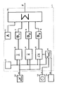
- the block diagram shows an electronic evaluation unit, designated overall by 1, which comprises a number of modules.
- a counter 2 is provided, the output line of which leads to a plurality of processing units 3, 4, 5 and to a map memory 6.
- the output line of the processing device 3 is connected to a memory 7, the output line of the processing device 4 to a memory 8 and the output line of the processing device 5 to a memory 9.
- the outputs of these memories 7, 8 and 9 in turn lead to a summer 10, which also receives a signal from another memory 11.
- the block diagram shows an accelerator pedal 12, the position of which is converted into a proportional accelerator pedal signal by a suitable device.
- the accelerator pedal controls an internal combustion engine, not shown, of a motor vehicle.
- the accelerator pedal signal is present at the processing device 3, the processing device 4 and the processing device 5 at the same time.
- the respective value is ⁇ i of the accelerator pedal signal during a predetermined time interval T A in the individual devices 3, 4 and 5 are read.
- the map memory 6 delivers a signal value ⁇ B at each interval, depending on the signal from the vehicle speed sensor 13 and the gear 14 engaged, which represents the required accelerator pedal position.
- the accelerator pedal signals are ⁇ i in the manner shown at the beginning processed in measurement signals representing the average accelerator pedal speed ⁇ , the middle accelerator pedal position ⁇ and the mean accelerator pedal deviation ⁇ ⁇ play.
- the measurement signal ⁇ is with the constant B1 of the memory 7, the measurement signal ⁇ with the constant B2 of the memory 8 and the value of ⁇ ⁇ multiplied by the constant B3 of the memory 9.
- the products determined in this way are now fed to the summer 10, where they are added with the constant A.
- the control signal resulting from this sum is present as driver factor F at the output of the evaluation device 1 for further use.
Landscapes
- Engineering & Computer Science (AREA)
- Mechanical Engineering (AREA)
- General Engineering & Computer Science (AREA)
- Chemical & Material Sciences (AREA)
- Combustion & Propulsion (AREA)
- Transportation (AREA)
- Control Of Transmission Device (AREA)
- Combined Controls Of Internal Combustion Engines (AREA)
Abstract
Die Erfindung beschreibt ein Verfahren zur Ermittlung eines Fahrerfaktors, dar den Fahrstil eines Fahrers wiedergeben soll. Dabei wird der Fahrerfaktor aus einem Fahrpedalsignal gewonnen und durch entsprechende Umformung in einer zentralen Auswerteeinheit (1) ermittelt. Der Fahrerfaktor dient in einer bevorzugten Anwendung zur Steuerung eines automatischen Getriebes, er kann aber auch zur Steuerung anderer hilfskraftbetätigter Aggregate wie Lenkhilfe usw. herangezogen werden.
Description
Die Erfindung bezieht sich auf ein Verfahren zum Ermitteln eines den Fahrstil eines Fahrers charakterisierenden Fahrerfaktors in einem mit einer Brennkraftmaschine angetriebenen Kraftfahrzeug nach dem Oberbegriff des Anspruchs 1.The invention relates to a method for determining a driver factor characterizing the driving style of a driver in a motor vehicle driven by an internal combustion engine.
Die Ermittlung eines solchen Fahrerfaktors zeigt die DE-PS 33 41 652. Der Fahrerfaktor wird hier zur Auswahl der jeweils optimalen, auf den Fahrtstil des Fahrers angepaßten Schaltkennlinie eines automatischen Getriebes herangezogen. Er wird dabei in der Weise ermittelt, daß eine Rechnereinheit das der Stellung des Fahrpedals proportionale Fahrpedalsignal zyklisch oder antizyklisch abfragt und den abgetasteten Wert in einer Fahrpedalspeichereinheit ablegt. Aus den einzelnen abgespeicherten Werten errechnet die Fahrpedalrechnereinheit über ein gewichtete Summe eine den Fahrstil des Fahrers repräsentierende Fahrpedalaktivität bzw. den Fahrerfaktor.DE-PS 33 41 652 shows how such a driver factor is determined. The driver factor is used here to select the optimum shift characteristic curve of an automatic transmission, which is adapted to the driver's driving style. It is determined in such a way that a computer unit polls the accelerator pedal signal proportional to the position of the accelerator pedal cyclically or anticyclically and stores the sampled value in an accelerator pedal memory unit. From the individual stored values, the accelerator pedal computing unit uses a weighted sum to calculate an accelerator pedal activity or driver factor that represents the driver's driving style.
Auf die Art und Weise der Verarbeitung der Fahrpedalsignale zu dem Fahrerfaktor geht die Vorveröffentlichung nicht näher ein. Es ist daher Aufgabe der Erfindung, die Ermittlung eines, den Fahrtstil eines Fahrers wiedergebenden Fahrerfaktor, der auf das jeweilige Fahrzeug abgestimmt ist, darzustellen.The prior publication does not go into detail on the manner in which the accelerator pedal signals are processed to form the driver factor. It is therefore an object of the invention Determination of a driver factor reflecting the driving style of a driver that is matched to the respective vehicle.
Die Aufgabe wird erfindungsgemäß mit den kennzeichnenden Verfahrensschritten nach Anspruch 1 gelöst. Ausgestaltungen der Erfindung ergeben sich aus den Unteransprüchen. Der Erfindung liegt folgender Algorithmus zugrunde:

Dabei bezeichnet F den zu ermittelnde Fahrerfaktor.
F denotes the driver factor to be determined.

Zur Bestimmung der fahrzeugspezifischen Koeffizienten A, B₁, B₂ und B₃ wir folgendermaßen vorgegangen: In vier verschiedenen Fahrzyklen werden die Größen
In einer Ausgestaltung der Erfindung wird nicht nur ein Fahrerfaktor ermittelt, sondern deren zwei. Dabei sind die Zeitintervalle, über die die Kenngrößen
In einem bevorzugten Anwendungsfall wird der Fahrerfaktor zur Steuerung eines automatischen Getriebes herangezogen. In Abhängigkeit von seiner Größe wird in einem Schaltkennfeld eine entsprechende Schaltkennlinie ausgewählt. Dadurch ist es möglich, eine derart kennfeldgesteuerte Getrieberegelung so auszulegen, daß sie genau die Schaltungen ausführt, die der Fahrer bei einer manuellen Getriebeschaltung durchführen würde. Dabei läßt sich das Kennfeld in der Weise auslegen, daß für bestimmte Fahrerfaktoren (zwischen 0 und 1) im Versuch Schaltkennlinien festgelegt werden und zwischen diesen vorgegebenen Stützstellen interpoliert wird.In a preferred application, the driver factor is used to control an automatic transmission. Depending on its size, a corresponding switching characteristic is selected in a switching map. This makes it possible to design such a map-controlled transmission control in such a way that it carries out precisely the gearshifts that the driver would carry out with a manual gearshift. The characteristic diagram can be designed in such a way that switching characteristic curves are determined for certain driver factors (between 0 and 1) and interpolated between these predetermined support points.
Um eine derartige Getriebesteuerung zu einer Getrieberegelung zu erweitern, wird die Reaktion des Fahrers auf einen Schaltvorgang beobachtet, zurückgeführt und in der Auswerteeinheit gegebenenfalls zur Korrektur des Fahrerfaktors verwendet.In order to expand such a transmission control to a transmission control, the driver's reaction to a shift operation is observed, traced back and, if necessary, used in the evaluation unit to correct the driver factor.
Die Verwendung eines Fahrerfaktors ist nicht allein auf die Steuerung des Getriebes beschränkt. So sind in einem Fahrzeug eine ganze Anzahl von Aggregaten vorhanden, die hilfskraftbetätigt werden. Als Beispiel sei hier genannt: Lenkhilfe, Bremskraftunterstützung, aktive Stoßdämpferbeeinflussung, Reifendruckregelung, Hinterradlenkung, Antiblockierbremssystem, Antriebsschlupfregelung und Kupplungssteuerung. Zur aktiven Beeinflussung dieser Systeme kann der Fahrerfaktor ebenfalls herangezogen werden. Dabei wird von der Annahme ausgegangen, daß ein Fahrer, der in sparsamer Weise sein Fahrzeug bewegt, beispielsweise eher eine leichtgängigere Lenkung wünscht als derjenige, der das Fahrzeug sportlich betreibt.The use of a driver factor is not limited to controlling the transmission alone. There are a number of units in a vehicle that are operated by auxiliary personnel. Examples include: steering assistance, brake power assistance, active shock absorber control, tire pressure control, rear wheel steering, anti-lock braking system, traction control and clutch control. The driver factor can also be used to actively influence these systems. It is based on the assumption that a driver who moves his vehicle sparingly wants, for example, more smooth steering than the person who operates the vehicle in a sporty manner.
In einer weiteren Ausgestaltung der Erfindung wird der einmal ermittelte Fahrerwert in einer Memoryschaltung abgelegt. Sobald der Fahrer einsteigt und durch Schlüsselbetätigung oder Knopfdruck seine Identität zu erkennen gibt, schaltet das System auf den für diesen Fahrer ermittelten Fahrerfaktor. Dies kann in gleicher Weise wie bei einer Sitzmemoryschaltung geschehen bzw. mit einer solchen Schaltung verbunden sein.In a further embodiment of the invention, the driver value determined once is stored in a memory circuit. As soon as the driver gets in and reveals his identity by pressing a key or pressing a button, the system switches to the driver factor determined for this driver. This can be done in the same way as with a seat memory circuit or can be connected to such a circuit.
Die Ermittlung des Fahrerfaktors aus dem Gaspedalsignal ist nachfolgend anhand eines Blockschaltbilds näher beschrieben.The determination of the driver factor from the accelerator pedal signal is described in more detail below using a block diagram.
Das Blockschaltbild zeigt eine insgesamt mit 1 bezeichnete, elektronische Auswerteeinheit die eine Anzahl von Bausteinen umfaßt. Zunächst ist ein Zähler 2 vorgesehen, dessen Ausgangsleitung zu mehreren Verarbeitungseinheiten 3, 4, 5 und zu einem Kennfeldspeicher 6 führt. Die Ausgangsleitung der Verarbeitungseinrichtung 3 ist mit einem Speicher 7, die Ausgangsleitung der Verarbeitungseinrichtung 4 mit einem Speicher 8 und die Ausgangsleitung der Verarbeitungseinrichtung 5 mit einem Speicher 9 verbunden. Die Ausgänge dieser Speicher 7, 8 und 9 wiederum führen auf einen Summierer 10, der auch Signal erhält von einem weiteren Speicher 11.The block diagram shows an electronic evaluation unit, designated overall by 1, which comprises a number of modules. First, a
Desweiteren zeigt das Blockschaltbild ein Fahrpedal 12, dessen Stellung durch eine geeignete Einrichtung in ein proportionales Fahrpedalsignal umgewandelt wird. Das Fahrpedal steuert dabei eine nicht dargestellte Brennkraftmaschine eines Kraftfahrzeuges. Das Fahrpedalsignal liegt gleichzeitig an der Verarbeitungseinrichtung 3, der Verarbeitungseinrichtung 4 und der Verarbeitungseinrichtung 5 an.Furthermore, the block diagram shows an
In Intervallen, die durch den Zähler 2 vorgegebenen werden, wird der jeweilige Wert αi des Fahrpedalsignals während eines vorgegebenen Zeitabschnitts TA in die einzelnen Einrichtungen 3, 4 und 5 eingelesen. Zugleich liefert bei jedem Intervall der Kennfeldspeicher 6, abhängig vom Signal des Fahrgeschwindigkeitssensors 13 und vom eingelegten Gang 14, der Verarbeitungseinrichtung 5 einen Signalwert αB , der die jeweilige Bedarfs-Fahrpedalstellung wiedergibt.At intervals which are predetermined by the
In den Verarbeitungseinrichtungen 3, 4 und 5 werden die Fahrpedalsignale αi in der eingangs aufgezeigten Weise in Meßsignale verarbeitet, die die mittlere Fahrpedalgeschwindigkeit
Claims (5)
Applications Claiming Priority (2)
| Application Number | Priority Date | Filing Date | Title |
|---|---|---|---|
| DE3941999 | 1989-12-20 | ||
| DE3941999A DE3941999C2 (en) | 1989-12-20 | 1989-12-20 | Method for determining a driver factor |
Publications (3)
| Publication Number | Publication Date |
|---|---|
| EP0433603A2 true EP0433603A2 (en) | 1991-06-26 |
| EP0433603A3 EP0433603A3 (en) | 1991-10-16 |
| EP0433603B1 EP0433603B1 (en) | 1993-12-01 |
Family
ID=6395845
Family Applications (1)
| Application Number | Title | Priority Date | Filing Date |
|---|---|---|---|
| EP90120165A Expired - Lifetime EP0433603B1 (en) | 1989-12-20 | 1990-10-20 | Method for determining a driving factor |
Country Status (2)
| Country | Link |
|---|---|
| EP (1) | EP0433603B1 (en) |
| DE (2) | DE3941999C2 (en) |
Cited By (12)
| Publication number | Priority date | Publication date | Assignee | Title |
|---|---|---|---|---|
| FR2697884A1 (en) * | 1992-11-12 | 1994-05-13 | Volkswagen Ag | Switching device for a gearbox. |
| EP0622570A1 (en) * | 1993-04-27 | 1994-11-02 | Siemens Aktiengesellschaft | Control system for vehicle automatic transmission |
| DE19524914A1 (en) * | 1995-07-08 | 1997-01-09 | Bosch Gmbh Robert | Adaptive transmission control |
| FR2746887A1 (en) * | 1996-03-26 | 1997-10-03 | Bosch Gmbh Robert | SYSTEM FOR DETERMINING VARIATIONS IN THE RATIO OF AN AUTOMATIC TRANSMISSION |
| DE19729251A1 (en) * | 1997-07-09 | 1999-02-11 | Daimler Benz Ag | Method for recognizing a spontaneous dynamic request from a driver of a motor vehicle |
| DE19730904A1 (en) * | 1997-07-18 | 1999-02-11 | Daimler Benz Ag | Method for evaluating actuations of the accelerator pedal by a vehicle driver in order to identify the activity and nervousness of the vehicle driver |
| FR2770605A1 (en) | 1997-11-03 | 1999-05-07 | Daimler Benz Ag | METHOD FOR ADAPTIVELY CONTROLLING, IN DRIVING BEHAVIOR, A VARIABLELY ADJUSTABLE MOTOR VEHICLE |
| WO1999025996A1 (en) * | 1997-11-14 | 1999-05-27 | Zf Friedrichshafen Ag | Process for controlling an automatic gearbox |
| DE19853603A1 (en) * | 1998-11-20 | 2000-06-08 | Bosch Gmbh Robert | User-recognizing anti-theft device |
| EP1531073A1 (en) * | 2003-11-17 | 2005-05-18 | Ford Global Technologies, LLC, A subsidary of Ford Motor Company | Method for regenerating energy in a vehicle |
| AT512909A4 (en) * | 2012-08-28 | 2013-12-15 | Avl List Gmbh | Method for operating a vehicle |
| CN108352125A (en) * | 2015-09-21 | 2018-07-31 | Cw与Sr投资有限公司 | Method and apparatus for emergency braking performance testing, evaluation and/or driver training |
Families Citing this family (6)
| Publication number | Priority date | Publication date | Assignee | Title |
|---|---|---|---|---|
| DE4219382B4 (en) * | 1992-06-13 | 2006-10-26 | Bayerische Motoren Werke Ag | Driving style adapted gear change control in electronically controlled automatic transmissions in motor vehicles |
| JP2888056B2 (en) * | 1992-10-02 | 1999-05-10 | 日産自動車株式会社 | Automatic transmission for vehicles |
| US6278362B1 (en) * | 1995-01-12 | 2001-08-21 | Honda Giken Kogyo Kabushiki Kaisha | Driving state-monitoring apparatus for automotive vehicles |
| DE19755076C2 (en) * | 1997-12-11 | 2000-05-31 | Zahnradfabrik Friedrichshafen | Automatic transmission with downshift function |
| DE102005034936A1 (en) * | 2005-07-27 | 2007-02-08 | Zf Lenksysteme Gmbh | Method for steering element control in motor vehicle steering system, by determining driver's driving behavior based on motor vehicle movement parameters e.g. lateral acceleration |
| DE102009026833A1 (en) | 2009-06-09 | 2010-12-16 | Zf Lenksysteme Gmbh | Method for driver identification in a vehicle |
Family Cites Families (13)
| Publication number | Priority date | Publication date | Assignee | Title |
|---|---|---|---|---|
| JPS57195951A (en) * | 1981-05-29 | 1982-12-01 | Toyota Motor Corp | Speed change method of automatic speed change gear |
| DE3341652A1 (en) * | 1983-11-18 | 1985-06-05 | Dr.Ing.H.C. F. Porsche Ag, 7000 Stuttgart | METHOD AND DEVICE FOR CONTROLLING A CLUTCH GEAR UNIT |
| JPS60161260A (en) * | 1984-01-31 | 1985-08-22 | Nissan Motor Co Ltd | vehicle steering system |
| AT378615B (en) * | 1984-02-01 | 1985-09-10 | Steyr Daimler Puch Ag | AUXILIARY DEVICE FOR OBTAINING OPTIMAL VALUES FOR COMMERCIAL VEHICLES |
| JPS61112851A (en) * | 1984-11-08 | 1986-05-30 | Diesel Kiki Co Ltd | Automatic speed change gear for vehicle |
| JPS61112852A (en) * | 1984-11-08 | 1986-05-30 | Diesel Kiki Co Ltd | Automatic speed change gear for vehicle |
| DE3621674A1 (en) * | 1985-07-05 | 1987-01-08 | Volkswagen Ag | TRANSMISSION SHIFT DEVICE |
| DE3627549A1 (en) * | 1986-08-13 | 1988-02-18 | Daimler Benz Ag | DEVICE FOR THE AUTOMATIC SWITCHING OF VEHICLE UNITS OF A MOTOR VEHICLE |
| JPS63212136A (en) * | 1987-02-27 | 1988-09-05 | Fuji Heavy Ind Ltd | Speed change controller for automatic speed change gear |
| US4829434A (en) * | 1987-04-29 | 1989-05-09 | General Motors Corporation | Adaptive vehicle |
| KR940000039B1 (en) * | 1987-08-19 | 1994-01-05 | 가부시기가이샤 히다찌세이사꾸쇼 | Electronic engine control apparatus |
| US5113721A (en) * | 1987-10-12 | 1992-05-19 | Auto Polly Gesellschaft M.B.H. | Method and apparatus for controlling a motor vehicle drive train |
| HU206654B (en) * | 1987-10-14 | 1992-12-28 | Csepeli Autogyar | Method for ratio switching of automatic or automatized mechanical synchronous gear box at motor vehicles |
-
1989
- 1989-12-20 DE DE3941999A patent/DE3941999C2/en not_active Expired - Fee Related
-
1990
- 1990-10-20 EP EP90120165A patent/EP0433603B1/en not_active Expired - Lifetime
- 1990-10-20 DE DE90120165T patent/DE59003696D1/en not_active Expired - Fee Related
Cited By (24)
| Publication number | Priority date | Publication date | Assignee | Title |
|---|---|---|---|---|
| FR2697884A1 (en) * | 1992-11-12 | 1994-05-13 | Volkswagen Ag | Switching device for a gearbox. |
| EP0622570A1 (en) * | 1993-04-27 | 1994-11-02 | Siemens Aktiengesellschaft | Control system for vehicle automatic transmission |
| DE19524914A1 (en) * | 1995-07-08 | 1997-01-09 | Bosch Gmbh Robert | Adaptive transmission control |
| FR2736408A1 (en) * | 1995-07-08 | 1997-01-10 | Bosch Gmbh Robert | ADAPTIVE CONTROL OF A GEARBOX |
| US5857161A (en) * | 1995-07-08 | 1999-01-05 | Robert Bosch Gmbh | System for determining a gear ratio change in an automatic transmission |
| DE19524914B4 (en) * | 1995-07-08 | 2007-05-16 | Bosch Gmbh Robert | Method for determining transmission ratio changes in an automatic transmission |
| US5983153A (en) * | 1996-03-26 | 1999-11-09 | Robert Bosch Gmbh | System for determining gear ratio changes for an automatic transmission |
| FR2746887A1 (en) * | 1996-03-26 | 1997-10-03 | Bosch Gmbh Robert | SYSTEM FOR DETERMINING VARIATIONS IN THE RATIO OF AN AUTOMATIC TRANSMISSION |
| DE19729251B4 (en) * | 1997-07-09 | 2004-04-22 | Daimlerchrysler Ag | Method for detecting a spontaneous dynamic demand of a driver of a motor vehicle |
| US6278911B1 (en) | 1997-07-09 | 2001-08-21 | Daimler-Benz Aktiengesellschaft | Method for recognizing a spontaneous demand by a driver of a motor vehicle for a dynamic response |
| DE19729251A1 (en) * | 1997-07-09 | 1999-02-11 | Daimler Benz Ag | Method for recognizing a spontaneous dynamic request from a driver of a motor vehicle |
| DE19730904A1 (en) * | 1997-07-18 | 1999-02-11 | Daimler Benz Ag | Method for evaluating actuations of the accelerator pedal by a vehicle driver in order to identify the activity and nervousness of the vehicle driver |
| US6295000B1 (en) | 1997-07-18 | 2001-09-25 | Daimler Benz Aktiengesellschaft | Method for assessing actuations of the accelerator by a vehicle driver to detect nervousness |
| US6216068B1 (en) | 1997-11-03 | 2001-04-10 | Daimler-Benz Aktiengesellschaft | Method for driver-behavior-adaptive control of a variably adjustable motor vehicle accessory |
| FR2770605A1 (en) | 1997-11-03 | 1999-05-07 | Daimler Benz Ag | METHOD FOR ADAPTIVELY CONTROLLING, IN DRIVING BEHAVIOR, A VARIABLELY ADJUSTABLE MOTOR VEHICLE |
| DE19748424C2 (en) * | 1997-11-03 | 2003-04-17 | Daimler Chrysler Ag | Method for driving behavior adaptive control of a variably adjustable motor vehicle assembly |
| DE19748424A1 (en) * | 1997-11-03 | 1999-05-12 | Daimler Chrysler Ag | Procedure for running performance adaptive control of variably adjustable gearbox of motor vehicle |
| US6375597B1 (en) | 1997-11-14 | 2002-04-23 | Zf Friedrichshafen Ag | Process for controlling an automatic gearbox |
| WO1999025996A1 (en) * | 1997-11-14 | 1999-05-27 | Zf Friedrichshafen Ag | Process for controlling an automatic gearbox |
| DE19853603A1 (en) * | 1998-11-20 | 2000-06-08 | Bosch Gmbh Robert | User-recognizing anti-theft device |
| EP1531073A1 (en) * | 2003-11-17 | 2005-05-18 | Ford Global Technologies, LLC, A subsidary of Ford Motor Company | Method for regenerating energy in a vehicle |
| AT512909A4 (en) * | 2012-08-28 | 2013-12-15 | Avl List Gmbh | Method for operating a vehicle |
| AT512909B1 (en) * | 2012-08-28 | 2013-12-15 | Avl List Gmbh | Method for operating a vehicle |
| CN108352125A (en) * | 2015-09-21 | 2018-07-31 | Cw与Sr投资有限公司 | Method and apparatus for emergency braking performance testing, evaluation and/or driver training |
Also Published As
| Publication number | Publication date |
|---|---|
| EP0433603B1 (en) | 1993-12-01 |
| DE59003696D1 (en) | 1994-01-13 |
| EP0433603A3 (en) | 1991-10-16 |
| DE3941999A1 (en) | 1991-06-27 |
| DE3941999C2 (en) | 1997-03-20 |
Similar Documents
| Publication | Publication Date | Title |
|---|---|---|
| EP0433603B1 (en) | Method for determining a driving factor | |
| DE3878032T2 (en) | VEHICLE CONTROL SYSTEM. | |
| EP1105702B1 (en) | Methods and device for determining the mass of a vehicle | |
| DE3785112T2 (en) | Vehicle control system and method therefor. | |
| EP0813987B1 (en) | Method for controlling distance between a vehicle and other objects | |
| EP0531567B1 (en) | Control for automotive power train with an automatic transmission | |
| DE19641059B4 (en) | Control device and control method for controlling a continuously variable transmission | |
| EP0932033B1 (en) | Method and apparatus for determining the mass of a vehicle | |
| EP0694138B1 (en) | Process for controlling an automatic gearbox | |
| DE19918563A1 (en) | Estimating the mass of a motor vehicle from vehicle speed and push force data, e.g. for truck | |
| DE19932642B4 (en) | Apparatus and method for controlling a distance between two moving vehicles | |
| DE3539682C2 (en) | ||
| DE102019124700A1 (en) | DRIVE CONTROL DEVICE FOR A VEHICLE | |
| EP1028865A1 (en) | Drive regulating system for vehicles especially for motor vehicles | |
| DE4138822A1 (en) | DEVICE FOR DETECTING THE DRIVING RESISTANCE OF A VEHICLE | |
| DE4228413A1 (en) | Motor vehicle weight calculation - dividing difference between drive forces, measured at spaced times, by difference between accelerations measured at corresponding times, to form quotient | |
| DE102005016859A1 (en) | Device and method for controlling the deceleration of a vehicle | |
| DE112006002620T5 (en) | A deceleration control apparatus and method for a vehicle | |
| DE3138715A1 (en) | DEVICE AND METHOD FOR DETERMINING THE GEAR POSITION OF A GEARBOX | |
| DE3939303C2 (en) | Shift control device for an automatic transmission for motor vehicles | |
| DE4126314C2 (en) | Method and device for determining irregular conditions in engine performance by checking the current status of engine performance | |
| DE112019001435T5 (en) | VEHICLE CONTROL DEVICE AND VEHICLE CONTROL PROCEDURE | |
| EP0653730B1 (en) | Method and device for evaluating the manner of driving a motor vehicle | |
| EP0657668B1 (en) | Controlling method for drive units of motor vehicles | |
| DE3539684A1 (en) | Automatic transmission system for vehicles |
Legal Events
| Date | Code | Title | Description |
|---|---|---|---|
| PUAI | Public reference made under article 153(3) epc to a published international application that has entered the european phase |
Free format text: ORIGINAL CODE: 0009012 |
|
| AK | Designated contracting states |
Kind code of ref document: A2 Designated state(s): DE FR GB IT SE |
|
| PUAL | Search report despatched |
Free format text: ORIGINAL CODE: 0009013 |
|
| AK | Designated contracting states |
Kind code of ref document: A3 Designated state(s): DE FR GB IT SE |
|
| 17P | Request for examination filed |
Effective date: 19911105 |
|
| RAP3 | Party data changed (applicant data changed or rights of an application transferred) |
Owner name: BAYERISCHE MOTOREN WERKE AKTIENGESELLSCHAFT |
|
| 17Q | First examination report despatched |
Effective date: 19930421 |
|
| GRAA | (expected) grant |
Free format text: ORIGINAL CODE: 0009210 |
|
| AK | Designated contracting states |
Kind code of ref document: B1 Designated state(s): DE FR GB IT SE |
|
| PG25 | Lapsed in a contracting state [announced via postgrant information from national office to epo] |
Ref country code: SE Effective date: 19931201 |
|
| ET | Fr: translation filed | ||
| GBT | Gb: translation of ep patent filed (gb section 77(6)(a)/1977) |
Effective date: 19931209 |
|
| REF | Corresponds to: |
Ref document number: 59003696 Country of ref document: DE Date of ref document: 19940113 |
|
| ITF | It: translation for a ep patent filed | ||
| PLBE | No opposition filed within time limit |
Free format text: ORIGINAL CODE: 0009261 |
|
| STAA | Information on the status of an ep patent application or granted ep patent |
Free format text: STATUS: NO OPPOSITION FILED WITHIN TIME LIMIT |
|
| 26N | No opposition filed | ||
| PGFP | Annual fee paid to national office [announced via postgrant information from national office to epo] |
Ref country code: GB Payment date: 20011017 Year of fee payment: 12 |
|
| PGFP | Annual fee paid to national office [announced via postgrant information from national office to epo] |
Ref country code: FR Payment date: 20011030 Year of fee payment: 12 |
|
| PGFP | Annual fee paid to national office [announced via postgrant information from national office to epo] |
Ref country code: DE Payment date: 20011124 Year of fee payment: 12 |
|
| REG | Reference to a national code |
Ref country code: GB Ref legal event code: IF02 |
|
| PG25 | Lapsed in a contracting state [announced via postgrant information from national office to epo] |
Ref country code: GB Free format text: LAPSE BECAUSE OF NON-PAYMENT OF DUE FEES Effective date: 20021020 |
|
| PG25 | Lapsed in a contracting state [announced via postgrant information from national office to epo] |
Ref country code: DE Free format text: LAPSE BECAUSE OF NON-PAYMENT OF DUE FEES Effective date: 20030501 |
|
| GBPC | Gb: european patent ceased through non-payment of renewal fee |
Effective date: 20021020 |
|
| PG25 | Lapsed in a contracting state [announced via postgrant information from national office to epo] |
Ref country code: FR Free format text: LAPSE BECAUSE OF NON-PAYMENT OF DUE FEES Effective date: 20030630 |
|
| REG | Reference to a national code |
Ref country code: FR Ref legal event code: ST |
|
| PG25 | Lapsed in a contracting state [announced via postgrant information from national office to epo] |
Ref country code: IT Free format text: LAPSE BECAUSE OF NON-PAYMENT OF DUE FEES;WARNING: LAPSES OF ITALIAN PATENTS WITH EFFECTIVE DATE BEFORE 2007 MAY HAVE OCCURRED AT ANY TIME BEFORE 2007. THE CORRECT EFFECTIVE DATE MAY BE DIFFERENT FROM THE ONE RECORDED. Effective date: 20051020 |