EP0433701A2 - Soupape actionnée par pression - Google Patents
Soupape actionnée par pression Download PDFInfo
- Publication number
- EP0433701A2 EP0433701A2 EP19900122480 EP90122480A EP0433701A2 EP 0433701 A2 EP0433701 A2 EP 0433701A2 EP 19900122480 EP19900122480 EP 19900122480 EP 90122480 A EP90122480 A EP 90122480A EP 0433701 A2 EP0433701 A2 EP 0433701A2
- Authority
- EP
- European Patent Office
- Prior art keywords
- pressure
- valve body
- flow
- actuated
- valve
- Prior art date
- Legal status (The legal status is an assumption and is not a legal conclusion. Google has not performed a legal analysis and makes no representation as to the accuracy of the status listed.)
- Withdrawn
Links
Images


Classifications
-
- F—MECHANICAL ENGINEERING; LIGHTING; HEATING; WEAPONS; BLASTING
- F16—ENGINEERING ELEMENTS AND UNITS; GENERAL MEASURES FOR PRODUCING AND MAINTAINING EFFECTIVE FUNCTIONING OF MACHINES OR INSTALLATIONS; THERMAL INSULATION IN GENERAL
- F16F—SPRINGS; SHOCK-ABSORBERS; MEANS FOR DAMPING VIBRATION
- F16F9/00—Springs, vibration-dampers, shock-absorbers, or similarly-constructed movement-dampers using a fluid or the equivalent as damping medium
- F16F9/32—Details
- F16F9/44—Means on or in the damper for manual or non-automatic adjustment; such means combined with temperature correction
- F16F9/46—Means on or in the damper for manual or non-automatic adjustment; such means combined with temperature correction allowing control from a distance, i.e. location of means for control input being remote from site of valves, e.g. on damper external wall
-
- F—MECHANICAL ENGINEERING; LIGHTING; HEATING; WEAPONS; BLASTING
- F16—ENGINEERING ELEMENTS AND UNITS; GENERAL MEASURES FOR PRODUCING AND MAINTAINING EFFECTIVE FUNCTIONING OF MACHINES OR INSTALLATIONS; THERMAL INSULATION IN GENERAL
- F16F—SPRINGS; SHOCK-ABSORBERS; MEANS FOR DAMPING VIBRATION
- F16F9/00—Springs, vibration-dampers, shock-absorbers, or similarly-constructed movement-dampers using a fluid or the equivalent as damping medium
- F16F9/32—Details
- F16F9/34—Special valve constructions; Shape or construction of throttling passages
-
- B—PERFORMING OPERATIONS; TRANSPORTING
- B60—VEHICLES IN GENERAL
- B60G—VEHICLE SUSPENSION ARRANGEMENTS
- B60G2600/00—Indexing codes relating to particular elements, systems or processes used on suspension systems or suspension control systems
- B60G2600/22—Magnetic elements
- B60G2600/26—Electromagnets; Solenoids
Definitions
- the invention relates to a pressure-operated valve according to the preamble of the main claim.
- the pressure-actuated valve comprises a valve body which is actuated by a spring element in the closing direction against a valve seat. If the valve body sits on its valve seat, a flow opening is closed and a chamber containing an upstream pressure is separated from a chamber containing an downstream pressure.
- the valve body can close the flow opening, ie the valve body covers the flow opening.
- the inflow-side pressure acts on the valve body in the area of the flow opening.
- the part of the valve body covering the flow opening represents an effective pressure area for the inflow-side pressure. If the inflow-side pressure reaches a certain value, this pressure can lift the valve body against the closing force of the spring element from the valve seat and pressure medium can flow from the first chamber into the flow into the second chamber. Should also be a large flow of pressure medium from the first chamber into the second chamber can flow without the pressure medium flow in the area of the flow opening being throttled too much, the flow opening must be correspondingly large.
- the spring element must be dimensioned accordingly so that the spring element acting on the valve body can close the flow opening.
- the pressure medium can only flow from one specific chamber into the other chamber.
- the pressure-actuated valve has the function of a so-called pressure-maintaining valve or pressure-limiting valve or safety valve, based on this only possible flow direction. A flow through the known pressure-operated valve in the opposite direction is not possible.
- the pressure-actuated valve with the characterizing features of the main claim has the advantage that a relatively weak and therefore small-sized spring element can be used to secure a large pressure with a large possible flow opening.
- An intermediate pressure which forms in an intermediate chamber when the pressure-actuated valve opens provides the advantage that, as the pressure medium flow increases, the pressure on the inflow side remains more or less constant, as desired. It is even possible that the pressure on the inflow side decreases as the pressure medium flow increases. It is a question of dimensioning.
- the pressure-operated valve has the advantage that it can be built so that it can be flowed through in both directions of flow.
- the valve can advantageously be constructed in such a way that the pressure difference in the area of the valve is the same for both flow directions or, depending on the dimensioning, the respective pressure difference can be chosen differently for both flow directions.
- valve Since only one spring element is required to secure the respective upstream pressure for both flow directions, the valve is very simple and has a small size.
- the pressure-actuated valve advantageously has a relatively small and light construction, it is particularly suitable for protecting a pressure medium flow which is exchanged between work spaces of a damping system, in particular a shock absorber.
- the pressure-actuated valve can advantageously influence the damping force in the shock absorber. It can be present as the sole valve in the shock absorber or it can e.g. B. as an additional safety valve in parallel with another valve, e.g. B. an electromagnetically actuated valve.
- the pressure operated valve can be used in such a way that as soon as there is too much pressure in one of the work rooms, it opens a path to the other work room. Depending on the design of the pressure-actuated valve, both flow directions can be secured with a single pressure-actuated valve.
- FIGS. 1 to 4 each show an exemplary embodiment and FIGS. 5 to 7 show special details.
- the pressure-actuated valve according to the invention can be used in any system in which a pressure of a pressure medium is to be secured or a pressure difference between an upstream and an downstream pressure of the pressure medium is to be secured, set or controlled.
- a shock absorber was chosen as an application example for the pressure-actuated valve according to the invention.
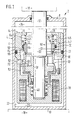
- FIG. 1 shows the first embodiment.
- a shock absorber 2 has a cylinder 4 with a casing tube 6, shown in sections, with a first end face 8 and with a second end face 10.
- a piston rod 12 protrudes from the first end face 8 of the casing tube 6. Only the two ends of the piston rod 12 are shown.
- the piston rod 12 is connected at one end to a stepped damper piston 14 and at the other end it is articulated on a first mass 16 indicated by dash-dotted lines. That is, the damper piston 14 is connected to the first mass 16.
- the damper piston 14 comprises a housing 15.
- the second End face 10 is connected to a second mass 18 indicated by dash-dotted lines.
- the first mass 16 is for example a vehicle body and the second mass 18 is e.g. B. a vehicle axle.
- the damper piston can slide axially with the interposition of a guide ring 20 on an inner lateral surface 22 of the tubular casing 6.
- the guide ring 20 also has the function of a seal.
- An interior of the cylinder 4 is divided into a first working space 24 and a second working space 26 by the damper piston 14. In the drawing, the first working space 24 is above and the second working space 26 is below the damper piston 14.
- the working spaces 24, 26 are at least partially filled with a pressure medium.
- the two working spaces 24, 26 are connected to one another via a flow connection 28.
- a throttle point 30 is provided in the course of the flow connection 28.
- the throttle point 30 can be changed by actuating a control slide 32.
- the control slide 32 is provided on the end face with a slide control edge 36.
- the control slide 32 can be actuated in the axial direction against a force of a spring 40.
- the slide control edge 36 of the control slide 32 increasingly lifts off the fixed control edge 34; d. H. with increasing current supply to the magnetic coil 38, a cross-sectional area at the throttle point 30 is increased.
- the solenoid 38 is not energized, the throttle point 30 is closed or the cross-sectional area reaches its minimum.
- the flow connection 28 comprises a spring chamber 42, a chamber 44, longitudinal openings 46, a groove 48, the throttle point 30, a slide chamber 50 and transverse openings 52. Is the pressure in the first Working space 24 larger than in the second working space 26, depending on the position of the control slide 32, the pressure medium can flow through the flow connection 28 in the order of enumeration. If the pressure in the second working space 26 is greater than in the first working space 24, then the pressure medium flows through the flow connection 28 in the opposite direction.
- the cross-sectional area of the throttle point 30 determines a damping force of the shock absorber 2. If the control slide 32 has a setting position in which the cross-sectional area of the throttle point 30 is very small and at the same time one of the masses 16, 18 is moved very quickly relative to the other mass 16, 18, this creates 2 large damping forces within the shock absorber, which means that, depending on the relative movement, a very high pressure is generated in one of the two working spaces 24, 26. If no further measures are provided, the pressure in one of the working spaces 24, 26 can possibly reach a level which could lead to failure of the shock absorber 2 or undesirably large damping forces occur. To prevent this, the pressure-actuated valve 60 according to the invention is installed in the flow connection 28 of the shock absorber 2.
- the pressure-actuated valve 60 comprises a valve body 62, a spring element 64, a sealing element 70 and at least one region of the housing 15 surrounding the valve body 62, the spring element 64 and the seal 70.
- the spring element 64 can consist of a spring or of several cooperating springs.
- Provided on the housing 15 of the damper piston 14 is a guide bore 66 which is approximately concentric with the piston rod 12.
- the valve body 62 has, roughly speaking, a sleeve-like shape with an outer guide jacket 68.
- the valve body 62 is mounted with its guide jacket 68 in the guide bore 66 of the housing 15 so as to be displaceable in the axial direction. So that by a between the guide jacket 68 of the valve body 62 and the guide bore 66 of the housing 15, no pressure medium can flow, a groove is inserted in the area of the guide bore 66 and the sealing element 70 is inserted therein.
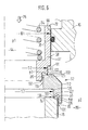
- valve body 62 is shown in FIG. 1 transversely to the circumference, but cut along its axis, as a result of which two mirror-image cut surfaces can be seen in FIG. For the purpose of clarification, one of these cut surfaces is shown again in FIG. 5 on a different scale. In all figures, the same or equivalent parts are provided with the same reference numerals.
- the sleeve-like valve body 62 has an end face 72 which extends into the spring chamber 42.
- the spring element 64 is installed in the spring chamber 42.
- the spring element 64 acts with one spring end against the housing 15 of the damper piston 14 and with its other spring end against the end face 72 of the valve body 62.
- the spring element 64 tries to actuate the valve body 62 with a closing force in a closing direction until the valve body 62 comes to rest on a shoulder 74 of the housing 15 which runs transversely to the closing direction.
- the closing direction is symbolically indicated in the drawing by an arrow 75.
- the part of the valve body 62 which comes into contact with the shoulder 74 of the housing 15 is referred to below as the valve body sealing region 76.
- the part of the housing 15 on which the valve body sealing region 76 comes to rest is referred to below as the counter-sealing region 78.
- the valve body sealing area 76 and the counter-sealing area 78 together form a sealing point 80
- the guide jacket 68 of the valve body 62 has a diameter denoted by D1.
- the sealing point 80 between the shoulder 74 of the housing 15 and the valve body 62 runs in a circular shape and has a diameter denoted by D2.
- the valve body 62 has one to the guide jacket 68 is approximately concentric inner bore jacket 82 with a diameter D3.
- a shoulder 84 is formed between the guide jacket 68 and the sealing point 80.
- the shoulder 84 on the valve body 62 extends transversely to the closing or opening direction in FIG. 5; however, as shown in FIG. 1, it can also run obliquely.
- an effective pressure area 85 is obtained from the area difference of the area with the diameter D1 minus the area with the diameter D2.
- the effective pressure area 85 of the valve body 62 protrudes into a chamber 86.
- the chamber 86 is connected to the slide chamber 50 via longitudinal bores 88.
- the same pressure p2 prevails in the chamber 86 as in the slide chamber 50 and, because of the transverse openings 52, also the same pressure p2 as in the second working chamber 26.
- the chamber 86 and the longitudinal bores 88 are also part of the flow connection 28.
- the pressure p2 prevailing in the chamber 86 acts on the effective pressure surface 85 of the valve body 62.
- a cylindrical part 90 can be provided on the valve body 62 between the shoulder 84 and the sealing point 80. The pressure prevailing in the chamber 86 can thus act unhindered up to the sealing point 80 and the valve body sealing region 76 of the valve body 62 is located on the end of the cylindrical part 90 of the valve body 62 which is preferably edge-shaped and faces the counter-sealing region 78.
- the pressure p1 prevails in the spring chamber 42, the chamber 44 and the longitudinal openings 46 as in the first working chamber 24.
- the pressure p1 is greater than the pressure p2 or pressure p1 is equal to pressure p2 or pressure p1 is less than pressure p2.
- the pressure p1 acts on the end face 72 of the valve body 62 in the closing direction symbolized by the arrow 75.
- the diameter D3 of the bore casing 82 is smaller than the diameter D2 of the sealing point 80.
- An annular part extending between the two diameters D2, D3 on the side of the valve body 62 facing away from the end face 72 is referred to below as the end face 92.
- a cylindrical shoulder 94 with a diameter D4 runs on the housing 15.
- the diameter D4 is smaller than the diameter D2.
- the end face 92 of the valve body 62 is graduated, u. a. because of a cylindrical shoulder 95 with a diameter D5.
- the diameter D5 is larger than the diameter D3, but smaller than the diameter D2 of the sealing point 80.
- the diameter D4 is slightly larger than the diameter D5.
- the cylindrical shoulder 95 of the valve body 62 overlaps the cylindrical shoulder 94 of the housing 15 in the axial direction, so that a narrow, annular throttle point 98 is formed between these two cylindrical shoulders 94, 95.
- the sealing point 80 is closed due to the closing force of the spring element 64.
- the force in the opening direction (counter to arrow 75) becomes increasingly larger, or with decreasing pressure p1 in chamber 44, the sum of the closing forces becomes increasingly smaller.
- the valve body sealing region 76 lifts off from the counter-sealing region 78 and a flow opening 100 opens between the valve body sealing region 76 of the valve body 62 and the counter-sealing region 78 of the housing 15. Pressure medium can now escape from the chamber 86 flow through the flow opening 100 in the direction of the chamber 44.
- the pressure p2 can also be referred to as the upstream pressure.
- the respective other pressure, here the pressure p1 in the chamber 44 can be referred to as the downstream pressure.
- the pressure medium is throttled again in the area of the throttle point 98, so that an intermediate pressure p3 forms in the area between the diameter D2 and the diameter D5, ie in the intermediate chamber 99, which, depending on Size of the flow opening 100 and the throttle point 98, is in the range between the pressure p2 and the pressure p1.
- the intermediate pressure p3 can be almost the same as the pressure on the inflow side. Since the intermediate pressure p3 is greater than the pressure p1, as soon as a certain flow area 100 is opened in the area of the sealing point 80, the valve body 62 is increasingly torn in the opening direction (counter to arrow 75), as a result of which a very large flow opening 100 can advantageously be formed immediately.
- the pressure-actuated valve 60 can be designed such that the pressure difference between the pressure p2 and the p1 remains largely constant regardless of a size of the pressure medium stream flowing through.
- the pressure p2 in the chamber 86 is greater than the pressure p1 in the chamber 44 and the pressure difference reaches a certain value, the flow opening 100 of the pressure-actuated valve 60 opens.
- the pressure-actuated valve 60 remains closed, regardless of the pressure difference.
- FIG. 2 shows an exemplary embodiment for this.
- Figure 2 shows the second embodiment.
- the diameter D2 of the sealing point 80 is larger than the diameter D1 of the guide jacket 68 of the valve body 62.
- the pressure-actuated valve 60 shown here therefore opens its flow opening 100 when the pressure p1 in the chamber 44 is sufficiently greater than the pressure p2 in the chamber 86, and the pressure medium can flow out of the chamber 44 in the direction of the chamber 86.
- the pressure p1 in the chamber 44 can be referred to as the upstream pressure.
- the intermediate chamber 99 and then the throttle point 98 adjoins the sealing point 80 in the direction of flow before the pressure medium reaches the chamber 86.
- the pressure-actuated valve 60 of the second exemplary embodiment can also keep the pressure p1 in the chamber 44 constant, irrespective of the size of the pressure medium stream flowing through, in a manner corresponding to that described for the first exemplary embodiment according to FIG. 1. It is possible for a person skilled in the art to transfer further details mentioned for the first exemplary embodiment with reference to FIGS. 1 and 5 to the second exemplary embodiment according to FIG. 2.
- one of the pressure-actuated valves 60 explained on the basis of the first two exemplary embodiments is installed in the shock absorber 2, then either the pressure p1 in the chamber 44, ie in the first working chamber 24, or the pressure p2 in the chamber 86, ie in the second working chamber 26, can be at one maximum value can be limited. If the pressures p1, p2 in both work spaces 24, 26 are to be limited with the pressure-actuated valve 60, two of the valves 60 shown in FIGS. 1 and 2 are to be installed in the flow connection 28 of the shock absorber 2. Since the pressure-actuated valves 60 are relatively small and since the required spring element 64 can be relatively weak and therefore small, it is often possible to install two pressure-actuated valves 60 in the shock absorber 2 without any problems.
- the variants of the pressure-actuated valve 60 offer the advantage that both the pressure p1 in the first working space 24 and the pressure p2 in the second working space 26 can be limited with a single pressure-actuated valve 60.
- the pressure-actuated valve 60 can be flowed through in two flow directions.
- Figure 3 shows the third embodiment.
- the valve body 62 comprises a first valve body part 111 and a second valve body part 112.
- a part of the pressure-actuated valve 60 shown in FIG. 3 is identified by a dash-dotted line and marked VI. This part of the pressure-actuated valve 60 is shown again in FIG. 6 for the purpose of illustration with a changed scale.
- first sealing point 115 and a first throttle point 116 between the first valve body part 111 and the second valve body part 112.
- a first intermediate chamber 117 is formed between them.
- second sealing point 119 and a second throttling point 120 between the second valve body part 112 and the housing 15.
- a second intermediate chamber 118 is also formed in between.
- the throttling points 116 and 120 are designed according to FIG. When the pressure-actuated valve 60 is closed, the sealing points 115, 119 separate the chamber 44 from the chamber 86.
- the second sealing point 119 has a diameter D7.
- the diameter of the first sealing point 115 is also denoted here by D2 and the diameter of the guide jacket 68 of the first valve body part 111 is denoted by D1.
- the diameter D7 of the second sealing point 119 is larger than the diameter D2 of the first sealing point 115. If the pressure p2 in the chamber 86 is greater than the pressure p1 in the chamber 44, then because D7 is larger than D2, the second valve body part 112 in Closing direction (arrow 75) pressed against shoulder 74 of housing 15; d. H. if p2 is greater than p1, then the second sealing point 119 is closed.
- first sealing point 115 When the first sealing point 115 is closed, a first valve body sealing region 121 of the first valve body part 111 in the form of a peripheral edge comes into contact with a first counter sealing region 122 of the second valve body part 112 facing the first valve body sealing region 121.
- Sealing point 119 is in the form of a circumferential edge with the diameter D7 and a second valve body sealing region 126 of the second valve body part 112 abuts a second counter-sealing region 127 which forms on the shoulder 74 of the housing 15.
- the diameter D2 of the first sealing point 115 is smaller than the diameter D1 of the guide jacket 68 of the first valve body part 111 of the valve body 62.
- the area difference of the surface with the diameter D1, minus the surface with the diameter D2, results in a on the first valve body part 111 the first effective pressure surface 131 facing the chamber 86.
- the pressure p2 prevailing in the chamber 86 can act on the first valve body part 111 in the opening direction (counter to arrow 75) via the pressure surface 131.
- pressure p2 in chamber 86 may be referred to as the upstream pressure.
- the pressure-actuated valve 60 operates as if the two valve body parts 111 and 112 were firmly joined together, and from a certain pressure difference between the pressure p1 and the pressure p2, only the second sealing point 119 between the second valve body part 112 and the housing can 15 open.
- the diameter D7 of the second sealing point 119 is larger than that Diameter D1 of the guide jacket 68 of the valve body 62.
- the resulting difference in the areas forms a second effective pressure surface 135 facing the chamber 44. Because of the second effective pressure surface 135 on the second valve body part 112, the second sealing point 119 between the second valve body part can start from a certain differential pressure 112 and the housing 15 open, whereby a second flow opening 136 is opened between the second valve body part 112 and the housing 15.
- Figure 4 shows the fourth embodiment.
- the diameter D2 of the first sealing point 115 between the first valve body part 111 and the second valve body part 112 is larger than the diameter D1 of the guide jacket 68
- the diameter D7 of the second sealing point 119 between the second valve body part 112 and the shoulder 74 of the housing 15 is smaller than the diameter D1 of the guide jacket 68 of the valve body 62.
- the first effective pressure surface 131 of the first valve body part 111 faces the chamber 44
- the second effective pressure surface 135 of the second valve body part 112 is the chamber 86 facing.
- the first flow opening 132 is opened and, with a corresponding pressure difference, when the pressure p2 in the chamber 86 is greater than the pressure p1 in the chamber 44, the second flow opening 136 between the second valve body part 112 and the housing 15 is opened.
- the first throttle point 116 is arranged behind the first sealing point 115.
- the second flow opening 136 comes in the region of the second flow opening 136 first the second sealing point 119 and then the second throttle point 120.
- first sealing point 115 and the first throttle point 116 there is the first intermediate chamber 117 and between the The second intermediate chamber 118 is located at the second sealing point 119 and the second throttling point 120. Further details explained with reference to FIG. 6 can also be applied analogously to the fourth exemplary embodiment.
- FIGS. 3 and 4 offer the additional advantage that the flow of the pressure medium can be influenced in the two possible flow directions. Since the pressure medium flows from the first working chamber 24 into the second working chamber 26 and sometimes in the opposite direction in many embodiments of the shock absorber 2, the third and fourth exemplary embodiments are particularly well suited for a large number of shock absorber embodiments.
- valve body 62 when the valve body 62 is actuated in the closing direction (arrow 75), the flow openings 100, 132, 136 of the respective sealing points 80, 115, 119 are essentially completely closed because the valve body sealing region 76, 121, which is formed in the form of an edge, 126 comes into contact with the respective counter sealing area 78, 122, 127.
- the pressure-actuated valve 60 explained with reference to FIGS. 1 to 6 belongs to the group of the so-called seat valves. However, it is also possible to design the valve body 62 or the valve body parts 111, 112 of the valve body 62 in a slide-like manner, which is to be explained with reference to FIG. 7.
- FIG. 7 shows a further possibility for designing the valve body 62 of the pressure-actuated valve 60 in the region of the flow opening 100 between the valve body 62 and the housing 15.
- the valve body 62 is designed in the manner of a slide.
- a shoulder 141 of the valve body 62 comes to a shoulder 142 of the housing 15 in the closed position Investment.
- the slide-shaped valve body 62 covers an edge on the housing 15 in the area of the sealing point 80 in the axial direction.
- An annular gap is present in the area of the sealing point 80.
- the annular gap in the area of the sealing point 80 is relatively small, so that an average diameter of this annular gap can be referred to as the diameter D2 of the first sealing point 80.
- the pressure-actuated valve 60 shown in detail in FIG. 7 can also be modified in such a way that the diameter D2 of the annular gap of the sealing point 80 is larger than the diameter D1 of the guide jacket 68, so that the ratios obtained are approximately the same as those in the figure 2 shown second embodiment.
- a further flow connection 146 with z. B. a further pressure-actuated valve 147, an aperture, an electromagnetically actuated valve or the like between the two working spaces 24, 26 may be present.
- the pressure-actuated valve 60 according to the invention can also be arranged in a flow connection which is not provided in the damper piston 14 but at another location inside or outside the shock absorber 2.
- the pressure-actuated valve 60 is arranged in the flow connection 28 parallel to the throttle point 30 which can be controlled via the control slide 32.
- the pressure-actuated valve 60 will be dimensioned such that, in the normal case, the damping force of the shock absorber 2 is controlled solely via the throttle point 30, and only when an unusually large external force that displaces the two masses 16, 18 against one another does the pressure p1 or p2 is sufficient to open the pressure-actuated valve 60.
- the pressure p1 or p2 in the working spaces 24, 26 can thus be limited to an uncritical value.
- the unusually large, the two masses 16, 18 mutually displacing force can, for. B. occur when the shock absorber 2 is installed in a vehicle between the vehicle body and the vehicle axle and when this vehicle runs at high speed over a high obstacle.
- the pressure-actuated valve 60 can also be present as the only valve in the flow connection 28 of the shock absorber 2. That means there can be further throttling points, e.g. B. the throttle point 30 and thus also the control slide 32 are omitted, and the pressure-actuated valve 60 is the only one that controls the damping force of the shock absorber 2 of the damping system.
- the pressure medium flows essentially radially from the outside inwards or from the inside outwards through the respective flow opening 100, 132, 136 in the region of the sealing point 80, 115, 119.
- the pressure medium flows into the the chamber 44 or 86 containing the downstream pressure flows in, it is deflected more or less, depending on how far the valve body 62 is actuated in the opening direction, in the axial direction, specifically against the opening direction.
- the pressure medium is deflected in the axial direction by the shoulder 95 of the valve body 62 or the valve body parts 111, 112.
- a particular advantage is that in all of the exemplary embodiments (FIGS. 1 to 7), given the inflow-side pressure, the size of the respective effective pressure area 85, 131, 135 is the only influence on the opening force.
- the effective pressure area 85, 131, 135 is completely independent of the flow opening 100, 132, 136 that can be opened.
- the spring element 64 only the size of the respectively effective pressure area 85, 131, 135 has to be taken into account to a large extent. So you can z. B.
- the sealing element 70 may be dispensed with.
- the embodiments of the pressure-actuated valve 60 according to FIGS. 3, 4 and 6 have the further advantage that the pressure medium flow can be influenced in both directions with a single pressure-actuated valve 60. Only one spring element 64 is advantageously required for this. Nevertheless, e.g. B. when the pressure medium flows from the first working space 24 into the second working space 26, the inflow-side pressure, ie the pressure p1 in the chamber 44 or in the first working space 24, can be brought to a high value and when the pressure medium flows from the second working space 26 in the first working space 24, the inflow-side pressure, ie the pressure p2 in the chamber 86 or in the second working space 26, can be kept very small.
- the inflow-side pressure ie the pressure p1 in the chamber 44 or in the first working space
- the same can be achieved if the effective pressure area 131 is selected to be relatively small and the effective pressure area 135 is relatively large for the pressure ratio mentioned as an example.
- the two respective inflow-side pressures p1 and p2 can thus be controlled independently of one another for both flow directions.
- the pressure-actuated valve 60 is particularly well suited for shock absorbers, in particular for so-called single-tube shock absorbers and also for so-called two-tube shock absorbers.
Landscapes
- Engineering & Computer Science (AREA)
- General Engineering & Computer Science (AREA)
- Mechanical Engineering (AREA)
- Safety Valves (AREA)
- Fluid-Damping Devices (AREA)
Applications Claiming Priority (2)
| Application Number | Priority Date | Filing Date | Title |
|---|---|---|---|
| DE3942545 | 1989-12-22 | ||
| DE3942545A DE3942545A1 (de) | 1989-12-22 | 1989-12-22 | Druckbetaetigtes ventil |
Publications (2)
| Publication Number | Publication Date |
|---|---|
| EP0433701A2 true EP0433701A2 (fr) | 1991-06-26 |
| EP0433701A3 EP0433701A3 (en) | 1992-11-04 |
Family
ID=6396182
Family Applications (1)
| Application Number | Title | Priority Date | Filing Date |
|---|---|---|---|
| EP19900122480 Withdrawn EP0433701A3 (en) | 1989-12-22 | 1990-11-26 | Pressure-activated valve |
Country Status (5)
| Country | Link |
|---|---|
| US (1) | US5137125A (fr) |
| EP (1) | EP0433701A3 (fr) |
| JP (1) | JPH04136574A (fr) |
| DE (1) | DE3942545A1 (fr) |
| HU (1) | HU908422D0 (fr) |
Cited By (6)
| Publication number | Priority date | Publication date | Assignee | Title |
|---|---|---|---|---|
| WO1993005315A1 (fr) * | 1991-09-06 | 1993-03-18 | Alfred Teves Gmbh | Dispositif a soupape pilotable pour amortisseurs de vibrations bitubes reglables |
| WO1993017254A1 (fr) * | 1992-02-29 | 1993-09-02 | Itt Automotive Europe Gmbh | Soupape d'amortisseur et procede de reglage continu de la force d'amortissement d'un amortisseur de vibrations reglable |
| WO1996015390A1 (fr) * | 1994-11-14 | 1996-05-23 | Industrieanlagen-Betriebsgesellschaft Mbh | Amortisseur de vibrations, notamment pour vehicules |
| WO2007085608A1 (fr) * | 2006-01-28 | 2007-08-02 | Continental Teves Ag & Co. Ohg | Vanne à commande électrique |
| EP2243979A3 (fr) * | 2009-04-23 | 2012-04-18 | ZF Friedrichshafen AG | Amortisseur d'oscillations réglable doté d'une soupape de fonctionnement d'urgence |
| DE102014224976A1 (de) * | 2014-12-05 | 2016-06-09 | Zf Friedrichshafen Ag | Dämpfventil |
Families Citing this family (12)
| Publication number | Priority date | Publication date | Assignee | Title |
|---|---|---|---|---|
| DE4041619A1 (de) * | 1990-12-22 | 1992-06-25 | Bosch Gmbh Robert | Zylinder |
| DE4123141C1 (fr) * | 1991-07-12 | 1992-07-30 | Boge Ag, 5208 Eitorf, De | |
| US5511759A (en) * | 1994-05-26 | 1996-04-30 | Steelcase, Inc. | Hydraulic chair height adjustment mechanism |
| BR9803729A (pt) * | 1997-07-29 | 1999-11-23 | Stabilus Gmbh | Grupo pistão-cilindro bloqueável. |
| SE523534C2 (sv) * | 1998-03-10 | 2004-04-27 | Oehlins Racing Ab | Ventil- eller tryckregulatoranordning för att effektuera öppnings och/eller stängningsfunktioner eller rörelser för två från och mot varandra arbetande delar, t ex kägla/slid respektive säte/hus. |
| US6392516B1 (en) | 1998-12-04 | 2002-05-21 | Tlx Technologies | Latching solenoid with improved pull force |
| US6198369B1 (en) | 1998-12-04 | 2001-03-06 | Tlx Technologies | Proportional actuator for proportional control devices |
| DE10140580A1 (de) * | 2000-12-16 | 2002-06-20 | Stabilus Gmbh | Kolben-Zylinderaggregat mit einer geschwindigkeitsabhängigen Dämpfkraft |
| US8684660B2 (en) | 2011-06-20 | 2014-04-01 | General Electric Company | Pressure and temperature actuation system |
| DE102015209318B4 (de) * | 2015-05-21 | 2022-05-12 | Zf Friedrichshafen Ag | Dämpfventileinrichtung |
| DE102024121727A1 (de) * | 2024-07-30 | 2026-02-05 | Rapa Automotive Gmbh & Co. Kg | Druckregelventil mit integrierter rückschlagfunktion |
| DE102024121725A1 (de) * | 2024-07-30 | 2026-02-05 | Rapa Automotive Gmbh & Co. Kg | Ventilpatrone mit rückschlagventil |
Family Cites Families (15)
| Publication number | Priority date | Publication date | Assignee | Title |
|---|---|---|---|---|
| GB706112A (en) * | 1951-03-05 | 1954-03-24 | Bastian Blessing Co | Safety valve device |
| US3034605A (en) * | 1961-03-14 | 1962-05-15 | Henry M Pernini | Hydraulic buffer |
| DE2036694A1 (de) * | 1970-07-24 | 1972-01-27 | Sempell Rhein Armaturen | Sicherheitsventil für inkompressible Medien |
| DE2727407C2 (de) * | 1977-06-18 | 1982-05-27 | Boge Gmbh, 5208 Eitorf | Ventileinrichtung, insbesondere für Teleskopschwingungsdämpfer von Kraftfahrzeugen |
| JPS55163344A (en) * | 1979-06-04 | 1980-12-19 | Kayaba Ind Co Ltd | Shock absorber |
| DE3015596A1 (de) * | 1980-04-23 | 1981-10-29 | Fichtel & Sachs Ag, 8720 Schweinfurt | Hydraulischer schwingungsdaempfer mit geraeuscharmen daempfventilen |
| FR2554201B1 (fr) * | 1983-10-27 | 1986-01-17 | Robatel Slpi | Clapet de securite pour le controle des pressions regnant dans deux enceintes separees |
| JPH0235060Y2 (fr) * | 1984-10-08 | 1990-09-21 | ||
| DE3513839A1 (de) * | 1985-04-17 | 1986-10-23 | Fritz Bauer + Söhne oHG, 8503 Altdorf | Fluidgefuellte gedaempfte kolben-zylinder-einheit |
| GB2196720B (en) * | 1986-10-29 | 1990-09-19 | Honda Motor Co Ltd | Valve structure in a hydraulic damper |
| DE3800864A1 (de) * | 1987-04-01 | 1988-10-20 | Bosch Gmbh Robert | Stossdaempfer ii |
| DE3800865A1 (de) * | 1987-04-01 | 1988-10-20 | Bosch Gmbh Robert | Stossdaempfer i |
| ES2030526T3 (es) * | 1988-02-15 | 1992-11-01 | Bendix Espana S.A. | Amortiguador de regimen variable. |
| US4946009A (en) * | 1989-04-12 | 1990-08-07 | Applied Power, Inc. | Electromagnetic valve utilizing a permanent magnet |
| US4972929A (en) * | 1989-06-07 | 1990-11-27 | Lord Corporation | Bidirectional dual disc valve assembly |
-
1989
- 1989-12-22 DE DE3942545A patent/DE3942545A1/de not_active Withdrawn
-
1990
- 1990-11-26 EP EP19900122480 patent/EP0433701A3/de not_active Withdrawn
- 1990-12-20 US US07/630,617 patent/US5137125A/en not_active Expired - Fee Related
- 1990-12-21 JP JP2404919A patent/JPH04136574A/ja active Pending
- 1990-12-21 HU HU908422A patent/HU908422D0/hu unknown
Cited By (7)
| Publication number | Priority date | Publication date | Assignee | Title |
|---|---|---|---|---|
| WO1993005315A1 (fr) * | 1991-09-06 | 1993-03-18 | Alfred Teves Gmbh | Dispositif a soupape pilotable pour amortisseurs de vibrations bitubes reglables |
| US5611413A (en) * | 1991-09-06 | 1997-03-18 | Itt Automotive Europe Gmbh | Controllable valve arrangement for controllable two-tube vibration absorbers |
| WO1993017254A1 (fr) * | 1992-02-29 | 1993-09-02 | Itt Automotive Europe Gmbh | Soupape d'amortisseur et procede de reglage continu de la force d'amortissement d'un amortisseur de vibrations reglable |
| WO1996015390A1 (fr) * | 1994-11-14 | 1996-05-23 | Industrieanlagen-Betriebsgesellschaft Mbh | Amortisseur de vibrations, notamment pour vehicules |
| WO2007085608A1 (fr) * | 2006-01-28 | 2007-08-02 | Continental Teves Ag & Co. Ohg | Vanne à commande électrique |
| EP2243979A3 (fr) * | 2009-04-23 | 2012-04-18 | ZF Friedrichshafen AG | Amortisseur d'oscillations réglable doté d'une soupape de fonctionnement d'urgence |
| DE102014224976A1 (de) * | 2014-12-05 | 2016-06-09 | Zf Friedrichshafen Ag | Dämpfventil |
Also Published As
| Publication number | Publication date |
|---|---|
| JPH04136574A (ja) | 1992-05-11 |
| US5137125A (en) | 1992-08-11 |
| DE3942545A1 (de) | 1991-06-27 |
| EP0433701A3 (en) | 1992-11-04 |
| HU908422D0 (en) | 1991-07-29 |
Similar Documents
| Publication | Publication Date | Title |
|---|---|---|
| DE4129581C2 (de) | Steuerbare Ventilanordnung für regelbare Zweirohr-Schwingungsdämpfer | |
| EP0433701A2 (fr) | Soupape actionnée par pression | |
| EP0634577B1 (fr) | Soupape à siège à deux voies sous forme de cartouche | |
| EP0400395B1 (fr) | Amortisseur de choc | |
| DE3932669C2 (de) | Hydraulischer Stoßdämpfer | |
| DE69005747T2 (de) | Ventil für hydraulische Flüssigkeit und ein mit einem solchen Ventil ausgerüsteter Dämpfer. | |
| EP1435028B1 (fr) | Soupape de regulation de pression, en particulier soupape de regulation de pression a action proportionnelle | |
| DE2545563A1 (de) | Hydraulischer daempfer fuer eine fahrzeugfederung | |
| EP0318816A2 (fr) | Amortisseur hydraulique de chocs et de vibrations à amortissement réglable | |
| DE4041619A1 (de) | Zylinder | |
| EP0325958A1 (fr) | Clapet à commande hydraulique | |
| EP1226478B1 (fr) | Soupape, notamment soupape de regulation de pression | |
| WO2016131908A1 (fr) | Amortisseur de vibrations réglable | |
| DE2134093C3 (de) | Druckreduzierventil | |
| DE102018219221A1 (de) | Druckbegrenzungsventil mit waagerechter Kennlinie und Nachsaugung | |
| DE2945911C2 (fr) | ||
| LU84377A1 (de) | Einstellbares drosselventil | |
| EP4487037A1 (fr) | Vanne | |
| EP0041247A2 (fr) | Dispositif asservi pour réglage de débit indépendant de la charge | |
| WO1999040349A1 (fr) | Soupape a limitation de pression | |
| EP0298245B1 (fr) | Dispositif d'amortissement | |
| DE102018203008B4 (de) | Ventilanordnung | |
| DE19938699B4 (de) | Feststeller zum Feststellen relativ zueinander beweglicher Objekte | |
| DE4022016A1 (de) | 2/2-wege-logikventil | |
| DE3715651A1 (de) | Doppelwirkendes sperrventil zum regulieren eines hydraulischen fluidflusses, insbesondere in einem stossdaempfer oder einem fluidfederungselement fuer ein kraftfahrzeug |
Legal Events
| Date | Code | Title | Description |
|---|---|---|---|
| PUAI | Public reference made under article 153(3) epc to a published international application that has entered the european phase |
Free format text: ORIGINAL CODE: 0009012 |
|
| AK | Designated contracting states |
Kind code of ref document: A2 Designated state(s): DE ES FR GB |
|
| RAP3 | Party data changed (applicant data changed or rights of an application transferred) |
Owner name: ROBERT BOSCH GMBH |
|
| PUAL | Search report despatched |
Free format text: ORIGINAL CODE: 0009013 |
|
| AK | Designated contracting states |
Kind code of ref document: A3 Designated state(s): DE ES FR GB |
|
| 17P | Request for examination filed |
Effective date: 19930407 |
|
| 17Q | First examination report despatched |
Effective date: 19940620 |
|
| STAA | Information on the status of an ep patent application or granted ep patent |
Free format text: STATUS: THE APPLICATION IS DEEMED TO BE WITHDRAWN |
|
| 18D | Application deemed to be withdrawn |
Effective date: 19941101 |