EP0433763B1 - Attachable electro-impulse de-icer - Google Patents
Attachable electro-impulse de-icer Download PDFInfo
- Publication number
- EP0433763B1 EP0433763B1 EP90123280A EP90123280A EP0433763B1 EP 0433763 B1 EP0433763 B1 EP 0433763B1 EP 90123280 A EP90123280 A EP 90123280A EP 90123280 A EP90123280 A EP 90123280A EP 0433763 B1 EP0433763 B1 EP 0433763B1
- Authority
- EP
- European Patent Office
- Prior art keywords
- structural member
- electrically conductive
- icer
- coil
- inductor coil
- Prior art date
- Legal status (The legal status is an assumption and is not a legal conclusion. Google has not performed a legal analysis and makes no representation as to the accuracy of the status listed.)
- Expired - Lifetime
Links
- 229910052751 metal Inorganic materials 0.000 claims description 33
- 239000002184 metal Substances 0.000 claims description 32
- 238000006073 displacement reaction Methods 0.000 claims description 13
- 239000011800 void material Substances 0.000 claims description 10
- 238000010276 construction Methods 0.000 claims description 9
- 229910052755 nonmetal Inorganic materials 0.000 claims description 6
- 238000012986 modification Methods 0.000 claims description 4
- 230000004048 modification Effects 0.000 claims description 4
- 229920001169 thermoplastic Polymers 0.000 claims description 2
- 239000004416 thermosoftening plastic Substances 0.000 claims description 2
- 239000010410 layer Substances 0.000 description 38
- 239000003990 capacitor Substances 0.000 description 15
- 238000000926 separation method Methods 0.000 description 10
- 239000000463 material Substances 0.000 description 9
- 238000000034 method Methods 0.000 description 9
- 230000001133 acceleration Effects 0.000 description 8
- 239000004020 conductor Substances 0.000 description 8
- 230000005672 electromagnetic field Effects 0.000 description 8
- 230000009471 action Effects 0.000 description 7
- 229910052782 aluminium Inorganic materials 0.000 description 7
- XAGFODPZIPBFFR-UHFFFAOYSA-N aluminium Chemical compound [Al] XAGFODPZIPBFFR-UHFFFAOYSA-N 0.000 description 7
- RYGMFSIKBFXOCR-UHFFFAOYSA-N Copper Chemical compound [Cu] RYGMFSIKBFXOCR-UHFFFAOYSA-N 0.000 description 6
- 239000010949 copper Substances 0.000 description 6
- 229910052802 copper Inorganic materials 0.000 description 6
- 230000006870 function Effects 0.000 description 6
- 238000009826 distribution Methods 0.000 description 5
- 239000000945 filler Substances 0.000 description 5
- 239000007769 metal material Substances 0.000 description 5
- 239000000853 adhesive Substances 0.000 description 4
- 230000001070 adhesive effect Effects 0.000 description 4
- 238000013459 approach Methods 0.000 description 4
- 239000002131 composite material Substances 0.000 description 4
- 230000000694 effects Effects 0.000 description 4
- 230000005291 magnetic effect Effects 0.000 description 4
- 238000012360 testing method Methods 0.000 description 4
- 230000035508 accumulation Effects 0.000 description 3
- 238000009825 accumulation Methods 0.000 description 3
- 239000004411 aluminium Substances 0.000 description 3
- 230000008901 benefit Effects 0.000 description 3
- 238000004519 manufacturing process Methods 0.000 description 3
- 239000004593 Epoxy Substances 0.000 description 2
- 239000004696 Poly ether ether ketone Substances 0.000 description 2
- 238000003491 array Methods 0.000 description 2
- 230000001419 dependent effect Effects 0.000 description 2
- 238000013461 design Methods 0.000 description 2
- 238000004146 energy storage Methods 0.000 description 2
- 239000011152 fibreglass Substances 0.000 description 2
- 230000006872 improvement Effects 0.000 description 2
- 230000006698 induction Effects 0.000 description 2
- 230000003534 oscillatory effect Effects 0.000 description 2
- 229920002530 polyetherether ketone Polymers 0.000 description 2
- 230000004044 response Effects 0.000 description 2
- 239000003381 stabilizer Substances 0.000 description 2
- 239000013077 target material Substances 0.000 description 2
- 229910000838 Al alloy Inorganic materials 0.000 description 1
- OKTJSMMVPCPJKN-UHFFFAOYSA-N Carbon Chemical compound [C] OKTJSMMVPCPJKN-UHFFFAOYSA-N 0.000 description 1
- 229910001200 Ferrotitanium Inorganic materials 0.000 description 1
- XUIMIQQOPSSXEZ-UHFFFAOYSA-N Silicon Chemical compound [Si] XUIMIQQOPSSXEZ-UHFFFAOYSA-N 0.000 description 1
- RTAQQCXQSZGOHL-UHFFFAOYSA-N Titanium Chemical compound [Ti] RTAQQCXQSZGOHL-UHFFFAOYSA-N 0.000 description 1
- 230000004913 activation Effects 0.000 description 1
- 239000002313 adhesive film Substances 0.000 description 1
- JUPQTSLXMOCDHR-UHFFFAOYSA-N benzene-1,4-diol;bis(4-fluorophenyl)methanone Chemical compound OC1=CC=C(O)C=C1.C1=CC(F)=CC=C1C(=O)C1=CC=C(F)C=C1 JUPQTSLXMOCDHR-UHFFFAOYSA-N 0.000 description 1
- 230000015572 biosynthetic process Effects 0.000 description 1
- 230000008859 change Effects 0.000 description 1
- 238000005336 cracking Methods 0.000 description 1
- 238000010586 diagram Methods 0.000 description 1
- 239000003989 dielectric material Substances 0.000 description 1
- 239000013536 elastomeric material Substances 0.000 description 1
- 238000005538 encapsulation Methods 0.000 description 1
- 230000003628 erosive effect Effects 0.000 description 1
- 239000011888 foil Substances 0.000 description 1
- 229910002804 graphite Inorganic materials 0.000 description 1
- 239000010439 graphite Substances 0.000 description 1
- 230000005484 gravity Effects 0.000 description 1
- 238000009434 installation Methods 0.000 description 1
- 239000002907 paramagnetic material Substances 0.000 description 1
- 238000011160 research Methods 0.000 description 1
- 238000009420 retrofitting Methods 0.000 description 1
- 229910052710 silicon Inorganic materials 0.000 description 1
- 239000010703 silicon Substances 0.000 description 1
- 238000005476 soldering Methods 0.000 description 1
- 239000010935 stainless steel Substances 0.000 description 1
- 229910001220 stainless steel Inorganic materials 0.000 description 1
- 238000003860 storage Methods 0.000 description 1
- 239000002344 surface layer Substances 0.000 description 1
- 239000012815 thermoplastic material Substances 0.000 description 1
- 239000010936 titanium Substances 0.000 description 1
- 238000012546 transfer Methods 0.000 description 1
- 230000007704 transition Effects 0.000 description 1
- 230000001960 triggered effect Effects 0.000 description 1
Images



Classifications
-
- B—PERFORMING OPERATIONS; TRANSPORTING
- B64—AIRCRAFT; AVIATION; COSMONAUTICS
- B64D—EQUIPMENT FOR FITTING IN OR TO AIRCRAFT; FLIGHT SUITS; PARACHUTES; ARRANGEMENT OR MOUNTING OF POWER PLANTS OR PROPULSION TRANSMISSIONS IN AIRCRAFT
- B64D15/00—De-icing or preventing icing on exterior surfaces of aircraft
- B64D15/16—De-icing or preventing icing on exterior surfaces of aircraft by mechanical means, e.g. pulsating mats or shoes attached to, or built into, surface
- B64D15/163—De-icing or preventing icing on exterior surfaces of aircraft by mechanical means, e.g. pulsating mats or shoes attached to, or built into, surface using electro-impulsive devices
Definitions
- the invention relates to de-icers for aircraft and, more particularly, to de-icers that operate by deforming ice-accumulating surfaces.
- structural members is intended to refer to any aircraft surface susceptible to icing during flight, including wings, stabilizers, engine inlets, rotors, and so forth. Attempts have been made since the earliest days of flight to overcome the problem of ice accumulation. While a variety of techniques have been proposed for removing ice from aircraft during flight, these techniques have had various drawbacks that have stimulated continued research activities.
- mechanical de-icing In mechanical de-icing, the leading edges of structural members are distorted in some manner so as to crack ice that has accumulated thereon for dispersal into the airstream.
- a popular mechanical de-icing technique is the use of expandable tube-like structures that are periodically inflatable. Inflation of the structures results in their expansion or stretching by 40% or more. Such expansion typically occurs over approximately 2-6 seconds and results in a substantial change in the profile of the de-icer, thereby cracking accumulated ice.
- expansion of the devices can negatively influence the airflow passing over the aircraft structure. Also, they are most effective when ice has accumulated to a substantial extent, approximately 6.35 mm -0.25 inch- or more, thereby limiting their effectiveness. Desirably, ice removal would be accomplished long before accumulations approximating 6.35 mm -0.25 inch- have been attained.
- a more recent mechanical de-icing technique utilizes internal "hammers” to distort the leading edges of structural members.
- Such an approach is exemplified by US-A-3 549 964, wherein electrical pulses from a pulse generator are routed to a coil of a spark-gap pressure transducer disposed adjacent the inner wall of the structural member.
- the primary current in the coil induces a current in the wall of the structural member and the magnetic fields produced by the currents interact so as to deform the member.
- US-A-3 672 610 and US-A-4 399 967 disclose aircraft de-icers that utilize energized induction coils to vibrate or torque the surface on which ice forms. Each of these devices employs electromagnetic coils or magneto-restrictive vibrators located on the side of the surface opposite to that on which ice accumulates.
- US-A-3 809 341 flat buses are arranged opposite one another, with one side of each bus being disposed adjacent an inner surface of an ice-collecting wall. An electric current is passed through each bus and the resulting interacting magnetic fields force the buses apart and deform the ice-collecting walls.
- US-A-4 690 353 A more recent approach is shown by US-A-4 690 353.
- US-A-4 690 353 one or more overlapped flexible ribbon conductors are imbedded in an elastomeric material that is affixed to the outer surface of a structural member.
- the conductors are fed large current pulses from a power storage unit.
- the resulting interacting magnetic fields produce an electroexpulsive force that distends the elastomeric member.
- the distension is almost instantaneous when a current pulse reaches the conductors, and is believed to be effective in removing thin layers of ice.
- US-A-4 690 353 is believed to be an improvement over previous mechanical de-icing techniques, certain drawbacks remain.
- One of the drawbacks relates to the direction of current flow in adjacent electrically conductive members. It is believed that the current flow disclosed in US-A-4 690 353 produces inefficiencies that significantly restrict the effectiveness of the device.
- an electro-repulsive separation system is known from US-A-4 875 644.
- the known de-icer includes a pair of sheet-like arrays each containing in spaced-apart relationship a plurality of ribbon-shaped electrically conductive members. Large current pulses of predetermined magnitude are fed to the conductors resulting in rapid and forceful separation of the first and second sheet-like arrays creating a void or cavity between them, thereby distorting an elastic outer surface layer causing ice that had accumulated thereon to be shattered and thrown off.
- the Electro-Repulsive Separation System Patent discloses a device that is an improvement over that disclosed in US-A-4 690 353.
- the electrically conductive members are arranged such that a greater electro-expulsive force can be generated than with the serpentine configuration disclosed in US-A-4 690 353.
- the Electro-Repulsive Separation System Patent teaches the delivery of a current pulse of predetermined magnitude, shape and duration that provides more effective de-icing action.
- an inductor coil which has no portions moving relative to each other, is positioned in proximity with the outer surface of a structural member.
- the coil has a first side that is disposed in contact with the surface and a second side that is spaced from the surface.
- the coil is movable away from and toward the surface.
- a support member is provided for the coil, the support member being flexible in order to permit the coil to move relative to the surface.
- a portion of the support member defines an ice-accumulating surface that moves in response to movement of the coil.
- the coil and support member are provided in an integral construction that can be bonded or otherwise attached to the leading edge of the structural member without modifying the structural member.
- An alternative embodiment of the invention calls for providing a further conductive iata (so-called metal target) that is disposed intermediate the coil and the support member. Another alternative embodiment calls for disposing the metal target intermediate the coil and the structural member. Yet an additional alternative embodiment calls for providing a metal target (doubler) that is attached to the inner surface of the structural member.
- the support member is rapidly, and forcefully, displaced away from the structural member upon passing a short-duration, high-current pulse through the coil.
- the structural member is metal
- the structural member functions as a target member and the coil is displaced away from the surface; if the structural member is non-metal (such as a composite material), and if a surface-contacting target is not used, the coil remains positioned against the surface.
- the current flow creates an electromagnetic field that induces eddy currents in the target, structural member (if metal), and support member (if metal). Upon collapse of the electromagnetic field in the coil, the support member is pulled rapidly to its rest position.
- the de-icer according to the invention is exceedingly effective, while avoiding many of the drawbacks of the prior art.
- Most of the forces that are applied to the structural member are compressive forces that are more easily accommodated than tensile forces that are produced by various other mechanical de-icers.
- the device can be fitted readily to structural members, either as part of new construction or as a retrofit.
- the device operates on an eddy current principle, it completely avoids problems arising from directional current flow, and it provides a more effective ice-shedding action than has been possible with previous devices. In part, the effectiveness of the device is enhanced because the ice-accumulating surface is displaced a relatively great distance at a high rate of acceleration. Although the displacement is not enough to negatively affect the airflow passing over the structural member, the displacement is more than 20 times greater than the displacement that occurs with such devices as are disclosed in prior eddy current-type de-icers. The device also produces about 20% greater eddy current induction than prior internally disposed eddy current de-icers because the coil and the target are in surface-to-surface contact with each other, or nearly so.
- the referenced internally disposed de-icers require a substantial gap between the coil and the structural member in order to prevent possible damage to the coil upon rebounding of the structural member.
- the efficiency of the present invention also is great because the ice-accumulating surface that is displaced is relatively thin and is resiliently mounted to the structural member. In those de-icers that distort the structural member itself, the ice-accumulating surface is relatively thick and may be relatively difficult to distort.
- the present invention provides a technique especially adapted for de-icing the leading edges of structural members.
- De-icing is the removal of ice subsequent to its formation upon a leading edge.
- a leading edge is that portion of a structural member that functions to meet and break an airstream impinging upon the surface of the structural member. Examples of leading edges are the forward portions of wings, stabilizers, struts, nacelles, rotors, and other housings and protrusions first impacted by an airstream.
- FIGS 1-3 illustrate a known mechanical de-icer 10 and electrical circuitry therefor.
- the de-icer 10 includes first and second coils 12 that are disposed within a structural member (such as a wing) 14 near the backside of the leading edge thereof.
- the surface of the structural member 14 is made of metal such as aluminium which will be referred to as the "skin.”
- the coils 12 are mounted to a spar 16 by means of a mounting bracket 18.
- the coils 12 are circular in plan view.
- a circular, unalloyed aluminium disk 20 is bonded to the inner surface of the leading edge directly opposite each of the coils 12.
- each coil 12 is connected in series with an energy storage capacitor 22 and a thyristor 24.
- a diode 26 is connected in parallel with the capacitor 22.
- An electrical impulse is initiated by supplying a trigger pulse to the thyristor 24, allowing the capacitor 22 to discharge through the coil 12. Because the thyristor 24 has diode properties, the current follows the first positive loop of the RLC response, after which the thyristor 24 reopens the circuit. This leaves the capacitor 22 reverse-charged. Such reverse-charging reduces capacitor life substantially. For that reason, the diode 26 is placed across the capacitor 22.
- FIG. 3 a typical spanwise installation of the coils 12 within a wing is shown.
- Each of the coils 12 is separated laterally from other coils 12 by about 40.64 cm -16 inches-.
- the coils 12 are supplied a single power unit 28 that includes a transformer 30.
- the capacitor 22 is connected across the secondary side of the transformer 30.
- a switching device 32 is connected to each of the thyristors 24 in order to provide a trigger pulse to the thyristors 24.
- the capacitor 22 When the capacitor 22 is discharged through each coil 12, a rapidly forming and collapsing electromagnetic field is created that induces eddy currents in the disk 20 and the metal skin 14.
- the electromagnetic fields resulting from current flow in the coil 12, the disk 20, and the skin 14 create a repulsive force of several hundred pounds magnitude, but with a duration of only a fraction of a millisecond.
- a small amplitude, high acceleration movement of the skin 14 acts to shatter, debond, and expel the ice.
- Two or three such "hits" are performed in short order, separated by the time required to recharge the capacitor 22, and then ice is permitted to accumulate again until it approaches an undesirable thickness.
- the coils 12 can be activated sequentially in order to create a "ripple" effect that is believed to be more effective in shedding ice due to the propogation of skin movement in both chordwise and spanwise directions.
- the referenced de-icer 10 depends for its effectiveness upon deformation of the skin.
- the displacement of the metal surface subject to icing is very limited; typically it requires three impact pulses to remove accumulated ice under all icing conditions.
- the skin is displaced only to a limited extent, it is necessary to produce high forces in order to accomplish even that limited displacement.
- An additional problem is that the forces are "negative" forces in that they apply a tensile load to the leading edge. Aircraft structural members are designed to better withstand compressive loads, rather than tensile loads.
- a de-icer according to the invention is indicated by the reference numeral 40.
- the de-icer 40 is similar to the de-icer 10 in that it employs a coil 42. However, as will be discussed below, the de-icer 40 differs significantly from the de-icer 10. The differences will be apparent from the description that follows.
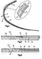
- the de-icer 40 as shown in Figure 4 is formed in an integral unit that is bonded or otherwise securely attached to the leading edge of a structural member.
- the leading edge, or skin, of the structural member is indicated by the reference numeral 44.
- the skin 44 will be made of metal such as an aluminium alloy.
- the coil 42 normally will be a multi-layer coil comprised of individual planar coil elements (see the discussion that follows with respect to Figures 9-11). In all of the embodiments described herein, the coil 42 is a unitary structure that has no portions that move relative to each other. For purposes of the present discussion, the coil 42 will be indicated schematically as a single element.
- the coil 42 includes a first surface that at rest is in contact with the exterior surface of the skin 44, and a second surface that is spaced from the skin 44. The coil 42 is not bonded to the skin 44, so that it can move away from and toward the skin 44.
- the second surface of the coil 42 is covered by a surface ply 46.
- the surface ply 46 preferably is not bonded to the second surface of the coil 42.
- the lateral edges of the coil 42 are abutted by a flexible, non-metallic filler layer 48 in order to provide a smooth transition with the contour of the skin 44.
- the de-icer 40 is bonded or otherwise securely attached to the skin 44 by means of the layer 48.
- the surface ply 46 is bonded to the layer 48. At the ends of the surface ply 46, the surface ply 46 is bonded or attached by a fastener (not shown) to the skin 44.
- the coil 42 and the surface ply 46 are able to move away from, and toward, the skin 44 intermediate the portions of the layer 48 that are bonded to the skin 44. It will be apparent from an examination of Figure 4 that the surface ply 46 not only forms a major portion of the exterior surface of the de-icer 40, but it also functions as a support member for the coil 42 (together with the layer 48) so as to keep the coil 42 properly positioned relative to the skin 44.
- the coil 42 preferably is made of unalloyed copper. Reference is made to EP-A-0 428 142 for a more complete description of the coil 42 and how it is manufactured.
- the surface ply 46 can be manufactured from any suitable metal commonly used for the exterior surfaces of structural members, such as aluminum, titanium or stainless steel foil.
- the surface ply 46 also could be made from a thin layer of thermoplastic film such as polyetherether ketone ("PEEK"). Such a material has excellent rain erosion characteristics, while being readily formed to any desired shape.
- PEEK polyetherether ketone
- the ply 46 can be made from other suitable non-metal materials, if desired.
- the adhesive used to bond the surface ply 46 to the layer 48 can be any adhesive commonly used to join surface plys to other parts of de-icers, although a modified epoxy film adhesive such as EA951 (manufactured by Hysol Corporation) is preferred.
- the filler layer 48 can be made of any known flexible, non-metallic material used with de-icers such as rubber, fiberglass, and the like.
- a schematic electrical circuit for the de-icer 40 is indicated by the reference numeral 60.
- the circuit 60 charges a bank of capacitors 62 (only one is illustrated for simplicity) which serve as high-voltage energy storage devices.
- the metal surface ply 46 and any target or doublers, if used, should be connected to the aircraft ground in order to minimize electromagnetic interference.
- a control pulse 64 is fed to a trigger circuit 66 which enables discharge of the capacitor 62 through one or more silicon controlled rectifiers (SCR's) 68 to provide a high-current pulse output 70 to the coil 42.
- SCR's silicon controlled rectifiers
- a dump load 72 which maintains the capacitors 62 in a discharged condition, is removed by opening a switch 74, thereby allowing charging current from a charging circuit 76 to charge the capacitors 62 to the desired voltage.
- the SCR 68 is triggered “on,” the capacitor bank 62 is discharged into the coil 42.
- a high-current pulse is produced, the magnitude of which is monitored by means of a current transformer 78.
- the current pulse may be a clean overdamped exponentially decaying sinusoidal waveform that is achieved by the RLC electrical circuit values.
- the circuit should be configured such that a rectifier 80 dumps the stored energy of the circuit inductance into the de-icer load, producing a single, non-oscillatory pulse having an extended trailing edge.
- the capacitor 62 has a capacitance of about 500 microfarads, and if the circuit 60 is operated as described previously, a current flow having a peak value of about 3000 amps at 1250 volts will be discharged through the coil 42.
- the coil rise time will be about 100 microseconds and the decay time will be about 200-300 microseconds.
- a strong electromagnetic field will be generated that will induce eddy currents in the skin 44 and the surface ply 46 (if metal).
- electromagnetic fields will be generated by the skin 44 and the surface ply 46.
- the electromagnetic fields thus generated will create a large repulsive force having a duration of only a fraction of a millisecond.
- the impact force will be transferred by the coil 42 to the surface ply 46, creating a small-amplitude, high-acceleration movement of the surface ply 46 that will be sufficient to break up and shed any ice that has accumulated.
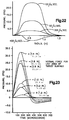
- FIG. 18 a plot of displacement, velocity and acceleration for the surface ply 46 is shown.
- the surface ply 46 is displaced about 1.651 mm -0.065 inch-, with a peak acceleration of about 18,750 times the acceleration due to gravity (G's) and with a peak velocity of about 965.2 cm -380 inches- per second.
- the compressive and expansive forces that are generated are reversed during collapse of the electromagnetic fields, thereby producing a pressure wave across the surface ply 46.
- the coil 42 and the surface ply 46 are rapidly pulled to the rest position shown in Figure 4.
- the peak retraction velocity is about 685.9 cm -270 inches- per second, and the peak acceleration is about 13,750 G's.
- the coil 42 and the surface ply 46 not only are repulsed from the skin 44, but they also are powered back toward the skin 44. As can be seen from an examination of Figure 18, there is minimal "bouncing" of the coil 42 and the surface ply 46 upon retraction against the skin 44. It also will be appreciated that the initial displacement of the coil 42 and the surface ply 46 away from the skin 44 apply primarily compressive loads to the skin 44, rather than tensile loads.
- FIG. 19 a plot of force versus coil current is shown for a laboratory force vice test.
- the lines bearing the reference numerals 90, 92, 94 are plots of force versus current for coils operating on the so-called electro-repulsive principle disclosed in the Electro-Repulsive Separation System Patent.
- the line labeled 96 is a plot of force versus current for a coil 42 operating according to the invention.
- Line 90 was generated using a four-layer serpentine coil.
- the line labeled 92 is a plot of the results utilizing a four-layer flat coil etched from rectangular sheets of copper.
- the line bearing the reference numeral 94 is a plot of the results utilizing a four-layer planar coil etched from square sheets of copper.
- the line bearing the reference numeral 96 is a plot of the results using a four-layer, planar, rectangular coil 42 operated according to the invention. As can be seen from reviewing Figure 19, the invention produced markedly superior results compared with any prior coils tested. The results were particularly dramatic compared with flat serpentine coils (line 90). At a coil current of 1700 amps, the planar coil 42 generated well over 453 kg -1000 pounds of repulsive force, whereas the serpentine coil generated less than 90.6 kg -200 pounds- of repulsive force.
- the de-icer 100 employs an attachment layer 102 that is bonded or otherwise securely attached to a metal skin 44 in substantial surface-to-surface contact.
- An additional target 104 (a so-called "doubler") can be disposed on the inner surface of the skin 44, if desired. It is advantageous to use the target 104 if the metal skin 44 is not thick enough to induce adequate eddy currents.
- the coil 42 is disposed on the outer side of the layer 102. The coil 42 is not bonded to the layer 102 so that the coil 42 can move away from, and toward, the layer 102.
- the surface ply 46 covers both the coil 42 and the layer 102.
- the filler layer 48 (only a portion of which is shown) provides a smooth contour with the skin 44 as in the embodiment described in Figure 4. It is expected that the layer 102 will be made of a non-metal material such as adhesive film, fiberglass, and the like.
- de-icer 100 can be manufactured as a prefabricated, integral unit for subsequent attachment to the skin 44. It is believed that the de-icer 100 will be easier to attach to the skin 44 than the de-icer 40. Further, because the layer 102 is attached to the skin 44 in substantial surface-to-surface contact, the attachment between the de-icer 100 and the skin 44 is exceedingly strong.
- FIG. 6 another alternative embodiment of the invention is indicated by the reference numeral 110.
- the de-icer 110 is similar to the de-icer 40, both in structure and operation, except that a metal target 112 is disposed on the second side of the coil 42, intermediate the coil 42 and the surface ply 46.
- the filler layer 48 is bonded to the skin 44 in substantial surface-to-surface contact, but the coil 42 is not bonded to the skin 44 so that it can move away from, and toward, the skin 44. It is expected that the skin 44 in the embodiment shown in Figure 6 will be made of a metal or composite material.
- the target 112 preferably is bonded to the ply 46 by an adhesive such as EA951.
- the coil 42 and the target 112 are separated by a thin separation ply, or release layer 116.
- the layer 116 enables the target 112 to move away from, and toward, the coil 42. It is expected that the target 112 will be made of a paramagnetic material such as aluminum.
- the release layer 116 can be made of a non-stick, thermoplastic material. A suitable material for the layer 116 is commercially available from the Richmond Division of Dixico Incorporated under the trademark A5000. If desired, the position of the coil 42 and the target 112 could be reversed such that the target 112 is in contact with the outer surface of the skin 44 and the coil 42 is bonded to the inner surface of the surface ply 46.
- the skin 44 is made of a composite material.
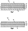
- the de-icer 120 includes a metal target 122 that is disposed on the second side of the coil 42.
- the coil 42 and the target 122 are separated by a separation ply, or release layer, indicated by the reference numeral 124.
- the filler layer 48 includes a backing portion 126 that extends across the front portion of the de-icer 120.
- the portion 126 is spaced from the outer surface of the target 122 by a void 128 and a release layer 130.
- the release layer 130 is in contact with the outer surface of the target 122.
- the surface ply 46 is bonded to the backing portion 126.
- the de-icer 120 enhances the force that otherwise can be applied to the surface ply 46.
- the coil 42 remains in contact with the skin 44.
- the release layer 124 remains attached to the target 122 and separates from the coil 42.
- the target 122 is displaced away from, and thereafter toward, the coil 42.
- the target 122 moves a considerable distance before the layer 130 impacts the backing portion 126.
- the momentum thus generated provides an enhanced impact force.
- a shorter-duration current pulse can be used to produce equivalent de-icing action compared with the de-icer 40.
- the skin 44 could be made of metal, in which case the target 122 would be eliminated. Further, the positions of the coil 42 and the target 122 could be reversed, as described with respect to the embodiment of Figure 6.
- an additional alternative embodiment of the invention is indicated by the reference numeral 130.
- the de-icer 130 is similar conceptionally to the de-icer 120. As illustrated, the skin 44 is made of metal. Instead of the void 128 being placed adjacent the backing portion 126, however, the void 128 is disposed intermediate the skin 44 and a release layer 132 that is in contact with the coil 42. In the de-icer 130, the target 122 has been eliminated, and the coil 42 is in contact with the inner surface of the backing portion 126. If the skin 44 is made of a composite material, then a metal target (not shown) could be used in conjunction with the coil 42. By using the de-icer 130, the retraction force that occurs during the fall of the shaped high-current pulse can enhance movement of the surface ply 46, thereby creating a very effective ice removal action.
- a first sheet-like member 140 is defined by a first, continuous electrical conductor having a plurality of turns 142, a first end 144 and a second end 146.
- the first end 144 defines an electrical input to the member 140, while the second end 146 defines an electrical output from the member 140.
- the member 140 is formed from a single sheet of unalloyed copper or aluminum having a thickness of about 0.016 inch.
- the turns 142 have a width within the range 0.070-0.125 inch.
- a second, sheet-like member 150 is defined by a second, continuous electrical conductor having a plurality of turns 152, a first end 154, and a second end 156.
- the first end 154 defines an electrical input to the member 150, while the second end 156 defines an electrical output from the member 150.
- the member 150 is formed from a single sheet of unalloyed copper or aluminum having a thickness of about 0.4064 mm -0.016 inch-.
- the turns 152 have a width within the range of 1.778-3.175 mm -0.070-0.125- inch.
- the members 140, 150 are illustrated in a "completely superimposed" coil arrangement indicated by the reference numeral 160.
- the turns 142 are disposed immediately adjacent comparable turns 152.
- the ends 146, 154 are joined as by soldering to form an electrical connection.
- electrical current directed into the first end 144 will follow a path through the turns 142 that is in the same direction as the current flow through the superimposed, adjacent turns 152.
- the first member 140 typically has 12-1/4 turns (8-1/4 turns are shown for clarity of illustration), as does the second member 150. Accordingly, the superimposed members 140, 150 define a coil 160 having 24-1/4 turns.
- the members 140, 150 are illustrated as being rectangular, they could be square, circular, or any other desired shape.
- a coil 170 is defined by a spiral-wound, continuous conductor that is formed from a flat ribbon having a width of approximately 4.826 mm -0.19 inch- and a thickness of approximately 0.635 mm -0.025 inch-.
- the coil 170 includes approximately 40 turns that are tightly wound to form an inner diameter of about 6.35 mm -0.25 inch- and an outer diameter of about 5.715 cm -2.25 inches-.
- the ends of the conductor are provided with connectors 172, 174 for connection to a source of electrical current.
- the coil 170 is less desirable than the coil 160, in part because of its greater thickness.
- the coils 160, 170 in conjunction with other components such as suitable dielectric materials and encapsulation materials, are used to manufacture the coil 42. Additional details concerning the coil 42, including the materials and techniques that can be used to manufacture it, can be found in EP-A-0 428 142.
- FIGs 13-15 various spanwise arrangements of the coils 42 are illustrated.
- the coils 42 are spaced approximately 16 inches, equidistantly on either aide of ribs 180.
- the de-icers 40 are aligned with each other at the centerline of the leading edge of the skin 44.
- the centerline is indicated by the dashed line 182 in Figures 13-15.
- upper and lower coils 42 are provided in a manner similar to that described for Figure 13. As in Figure 13, the coils 42 are spaced about 16 inches spanwise from each other, equidistantly on either side of the ribs 124 and equidistantly above and below the centerline 182.
- the coils 42 are staggered spanwise relative to the centerline 182. That is, one coil 42 is disposed above the centerline 182, while adjacent coils 42 are disposed an equal distance below the centerline 182. As with the embodiments illustrated in Figures 13 and 14, the coils 42 in Figure 15 are disposed about 40.64 cm -16 inches- apart, equidistantly on either side of the ribs 180.
- each coil 42 By arranging the coils 42 as shown in Figures 13-15, expansive forces generated by the coils 42 create a small amplitude, high acceleration movement and stress-producing wave across the leading edge of the skin 44, causing ice to be broken up and shed.
- the impulse force of each coil 42 is dependent upon the size and construction of the coil 42 and the overall de-icer construction (as illustrated in Figures 4-8).
- the coils 42 When the coils 42 are placed on the centerline 182 as shown in Figure 13, the coils 42 may be energized sequentially or simultaneously (as elements 1, 2, 3, etc.), or as odd or even groups (1, 3, 5..., or 2, 4, 6). In the configuration shown in Figure 14, the coils 42 may be energized sequentially or simultaneously as groups on the upper surface (1, 3, 5...) followed by groups on the lower surface (2, 4, 6...) or vice versa. The coils 42 also may be energized as staggered groups such as 1, 4, 5..., followed by 2, 3, 6..., or vice versa. In some cases, the number of coils 42 may be minimized as shown in Figure 15, and energized in groups such as 1, 3, 5..., followed by 2, 4, 6..., or simultaneously as a staggered group 1, 2, 3... . From the foregoing, it will be appreciated that the coils 42 can be attached to the skin 44 in a variety of placements and the coils 42 can be energized in a variety of sequences for effective de-icing action.
- the de-icer according to the invention shown in Figures 6 and 7 uses a target included as part of the de-icer itself without the requirement of using the skin of the structural member as a target.
- certain of the embodiments described herein use a metal skin to contribute to the resulting impact force produced by eddy currents, such usage of the skin is not necessary to proper functioning of the invention (except for the embodiment of Figure 4).
- the invention will function adequately with skins made of non-metal materials such as graphite/epoxy.
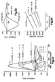
- a plot of pressure on a metal target (expressed as eddy current density) versus time at various radii is illustrated. Almost all of the pressure is generated within a distance of 1.25 times the radius of the inductor coil.
- targets utilized with the present invention need only approximate the size and shape of the inductor coil for effective force generation. At most, the target should have a radius 25% larger than that of the coil.
- FIG. 24 is a plot of radial in-plane force per unit area of target surface
- Figure 25 is a plot of radial distribution of in-plane force per unit target area.
- pressure is plotted versus time for various radii.
- pressure is plotted versus radius for various times.
- Figures 24 and 25 show that the eddy current-created force peaks rapidly and decays rapidly.
- Figures 24 and 25 also show that radial forces at a distance greater than 25% of coil radius are not significant.
- the impulse force produced by the inductor coil is dependent on the diameter of the target, the thickness of the target, and the material from which the target is made.
- the conductivity of the material as well as its thickness determine the eddy current that will be produced for a particular spacing between the inductor coil and the target.
- the shape of the inductor coil and the shape of the target also may be varied to obtain a maximum impulse force for a particular construction such as a curved airfoil.
- Figure 26 is a plot of impulse force versus target thickness for various target materials. Although copper is seen to produce the best impulse curve, other materials such as 1145 aluminium provide acceptable performance.
- target size and thickness include whether the target should be laminated (two or more layers) and whether the layers should be made of the same material. As to thickness, it is believed desirable to provide a target having a thickness of about one electrical skin depth for best impulse production. If desired, the target can be made of two layers -- one for strength and a second layer of different material having improved electrical conductivity. It has been found that increasing the target thickness increases the impulse produced. Nevertheless, the target generally should be kept as thin as possible in order to minimize weight and disruptions to the contour of the structural member. In work with the design of doublers (targets on inner surface of structural member), it has been found suitable to choose a doubler thickness that equals one-half the electrical skin depth at the circuit frequency.
- the electrical period should be chosen to be one-eighth that of the natural period. If the coil current has a long rise time, a thicker target is required. Test results with prior mechanical de-icers that employ doublers indicate that that the optimum electrical period is twice the mechanical period. It is believed that a similar relationship between the mechanical and electrical period apply to the present invention.
- Previous test results have utilized a uniform thickness of airfoil skin and/or doubler. It is possible that the thickness and shape of the target, and the spacing of the target from the coil, can be varied to tailor the force produced in the target and to enhance transfer of the force to ice-shedding surfaces.
Landscapes
- Engineering & Computer Science (AREA)
- Mechanical Engineering (AREA)
- Aviation & Aerospace Engineering (AREA)
- General Induction Heating (AREA)
- Linear Motors (AREA)
- Suspension Of Electric Lines Or Cables (AREA)
- Air Bags (AREA)
- Electromagnets (AREA)
Description
Claims (20)
- An electrically conductive structural member with a de-icer attached to its outer surface, the de-icer having an exposed surface upon which ice accumulates during flight, comprising:an electrically conductive member having a first side disposed in proximity with the outer surface of the electrically conductive structural member and a second side spaced from the outer surface of the electrically conductive structural member,support means (46,48) for supporting the electrically conductive member, the support means (46,48) being disposed in proximity with the second side of the electrically conductive member and defining the exposed surface of the de-icer, the support means (46,48) being flexible in order to dislodge ice accumulated on the exposed surface upon movement of the electrically conductive member relative to the electrically conductive structural member, andmeans (60) for supplying a short-duration, high-current electrical pulse to the electrically conductive member,
characterized in thatthe electrically conductive member is a unitary inductor coil (42) having no portions that move relative to each other, andthe inductor coil (42) and the support means (46,48) are formed in an integral construction that is attached to the outer surface of the electrically conductive structural member without modification of the electrically conductive structural member. - Electrically conductive structural member according to claim 1, characterized by a further electrically conductive member (112;122) in which an eddy current is induced upon supplying an electric pulse to the inductor coil (42), wherein the inductor coil (42), the support means (46,48) and the further member (112;122) are formed in an integral construction that is attachable to the outer surface of the structural member without modification of the structural member.
- De-icer especially adapted for attachment to the outer surface of an electrically non-conductive structural member, the de-icer having an exposed surface upon which ice accumulates during flight, comprising:an electrically conductive member having a first side disposed in proximity with the outer surface of the structural member and a second side spaced from the outer surface of the structural member,support means (46,48) for supporting the conductive member, the support means (46,48) being disposed in proximity with the second side of the conductive member and defining the exposed surface of the de-icer, the support means (46,48) being flexible in order to dislodge ice accumulated on the exposed surface upon movement of the conductive member relative to the structural member, andmeans (60) for supplying a short-duration, high-current electrical pulse to the conductive member,
characterized in thatthe electrically conductive member is a unitary inductor coil (42) having no portions that move relative to each other, anda further electrically conductive member (112;122) is provided in which an eddy current is induced upon supplying an electric pulse to the inductor coil (42), andthe inductor coil (42), the support means (46,48) and the further member (112;122) are formed in an integral construction that is attachble to the outer surface of the structural member without modification of the structural member. - De-icer or electrically conductive structural member according to any one of claims 1 to 3, characterized in that the support means (46,48) includes a non-metal layer (102) bonded to the structural member, and the inductor coil (42) is movable relative to the non-metal layer.
- De-icer or electrically conductive structural member according to any one of claims 1 to 4, characterized in that the inductor coil (42) is planar.
- De-icer or electrically conductive structural member according to any one of claims 1 to 5, characterized in that the inductor coil (42) is formed of multiple layers.
- De-icer or electrically conductive structural member according to any one of claims 1 to 6, characterized in that the support means (46,48) includes a flexible, non-metallic layer (48) that is bonded to the outer surface of the structural member, and a surface ply (46) overlying at least a portion of the flexible, non-metallic layer (48).
- De-icer or electrically conductive structural member according to claim 7, characterized in that the surface ply (46) is made of metal.
- De-icer or electrically conductive structural member according to claim 7, characterized in that the surface ply (46) is made of a thermoplastic film.
- De-icer or electrically conductive structural member according to any one of claims 1 to 9, characterized by a displacement void (128) disposed intermediate the first side of the inductor coil (42) and the outer surface of the structural member.
- De-icer or electrically conductive structural member according to claims 10 and 2 or 10 and 3, characterized in that the further conductive member (112;122) is disposed intermediate the inductor coil (42) and the outer surface of the structural member.
- De-icer or electrically conductive structural member according to any one of claims 1 to 9, characterized by a displacement void (128) disposed intermediate of the second side of the inductor coil (42) and the support means (46).
- De-icer or electrically conductive structural member according to claims 12 and 2 or 12 and 3, characterized in that the further conductive member (112;122) is disposed intermediate the inductor coil (42) and the displacement void (128).
- De-icer or electrically conductive structural member according to any one of claims 2 to 13, characterized in that the further conductive member (112;122) is disposed intermediate the first side of the inductor coil (42) and the outer surface of the structural member.
- De-icer or electrically conductive structural member according to any one of claims 2 to 13, characterized in that the further conductive member (122) is disposed intermediate the inductor coil (42) and the support means (46,48).
- De-icer or electrically conductive structural member according to any one of claims 1 to 15, characterized in that the support means (46,48) includes a metal portion disposed in proximity with the second side of the inductor coil (42).
- De-icer or electrically conductive structural member according to any one of claims 1 to 16, characterized by a metal portion (104) disposed on the inner surface of the structural member opposite the inductor coil (42).
- De-icer or electrically conductive structural member according to any one of claims 1 to 17, wherein the support means (46,48) includes a surface ply (46) made of metal disposed in proximity with the second side of the inductor coil (42).
- De-icer or electrically conductive structural member according to any one of claims 1 to 18, characterized in that the structural member includes a leading edge (44) having a centerline (182), and a first coil (42) is disposed above the centerline (182), and a second coil (42) is disposed below the centerline (182).
- De-icer or electrically conductive structural member according to any one of claims 1 to 19, characterized in that the structural member includes a leading edge (44) having a centerline (182), and a plurality of inductor coils (42) are spaced spanwise along the leading edge in the vicinity of the centerline (182).
Applications Claiming Priority (2)
| Application Number | Priority Date | Filing Date | Title |
|---|---|---|---|
| US455129 | 1989-12-22 | ||
| US07/455,129 US5129598A (en) | 1989-12-22 | 1989-12-22 | Attachable electro-impulse de-icer |
Publications (3)
| Publication Number | Publication Date |
|---|---|
| EP0433763A2 EP0433763A2 (en) | 1991-06-26 |
| EP0433763A3 EP0433763A3 (en) | 1991-07-31 |
| EP0433763B1 true EP0433763B1 (en) | 1998-11-18 |
Family
ID=23807535
Family Applications (1)
| Application Number | Title | Priority Date | Filing Date |
|---|---|---|---|
| EP90123280A Expired - Lifetime EP0433763B1 (en) | 1989-12-22 | 1990-12-05 | Attachable electro-impulse de-icer |
Country Status (9)
| Country | Link |
|---|---|
| US (2) | US5129598A (en) |
| EP (1) | EP0433763B1 (en) |
| JP (1) | JPH04208694A (en) |
| CN (1) | CN1026223C (en) |
| BR (1) | BR9006303A (en) |
| CA (1) | CA2032571A1 (en) |
| DE (1) | DE69032770T2 (en) |
| ES (1) | ES2127716T3 (en) |
| IL (1) | IL96615A (en) |
Families Citing this family (74)
| Publication number | Priority date | Publication date | Assignee | Title |
|---|---|---|---|---|
| US5326051A (en) * | 1992-06-30 | 1994-07-05 | The B. F. Goodrich Company | Electro-expulsive deicing system having circuit board expulsive members |
| US5609314A (en) * | 1994-06-02 | 1997-03-11 | The B. F. Goodrich Company | Skin for a deicer |
| US5356096A (en) * | 1992-12-30 | 1994-10-18 | The B. F. Goodrich Company | Skin for a deicer |
| US5314145A (en) * | 1992-12-30 | 1994-05-24 | The B.F. Goodrich Company | Compressible nose dynamic de-icer |
| CA2133397A1 (en) * | 1993-10-01 | 1995-04-02 | Michael John Giamati | Polyurethane deicer |
| US5429327A (en) * | 1993-10-22 | 1995-07-04 | The B.F. Goodrich Company | Electro-impulse de-icer |
| US5489073A (en) * | 1993-11-10 | 1996-02-06 | The B. F. Goodrich Company | Side flex leading edge ice protector |
| US5547150A (en) * | 1994-03-22 | 1996-08-20 | The B.F. Goodrich Company | Mechanical deicer having decoupled skin segments |
| US5553815A (en) * | 1994-04-07 | 1996-09-10 | The B. F. Goodrich Company | De-icer adapted for installment on the inner surface of a structural member |
| US5686003A (en) * | 1994-06-06 | 1997-11-11 | Innovative Dynamics, Inc. | Shape memory alloy de-icing technology |
| US5531405A (en) * | 1994-08-23 | 1996-07-02 | Dynamics Controls Corporation | Method of building an expulsive blanket using composite materials and stitched attachment |
| US6352601B1 (en) | 1994-12-27 | 2002-03-05 | The B. F. Goodrich Company | Self-adhering ice protector |
| US5743494A (en) * | 1995-03-07 | 1998-04-28 | The Bfgoodrich Company | Polyurethane deicer |
| RU2132292C1 (en) * | 1995-03-17 | 1999-06-27 | Попов Владимир Александрович | Method and device for deforming structure and its surrounding medium |
| RU2126763C1 (en) * | 1995-03-17 | 1999-02-27 | Попов Владимир Александрович | Gear for deformation of structure and medium that surrounds it |
| US5782435A (en) * | 1995-05-24 | 1998-07-21 | Cox & Company, Inc. | Electro-magnetic expulsion de-icing system |
| US5657952A (en) * | 1995-07-31 | 1997-08-19 | Dynamic Controls Hs, Inc. | Electro-expulsive de-icing apparatus and method of use |
| CA2204486A1 (en) | 1996-05-06 | 1997-11-06 | Richard Lawrence Rauckhorst Iii | Pneumatic deicing system with protection for super cooled large droplet ice |
| CA2227526A1 (en) | 1997-01-21 | 1998-07-21 | Michael J. Giamati | Hybrid deicer with element sequence control |
| EP0872417A1 (en) | 1997-04-16 | 1998-10-21 | The B.F. Goodrich Company | Hybrid deicer |
| US6283411B1 (en) | 1998-01-21 | 2001-09-04 | The B.F. Goodrich Company | Hybrid deicer with element sequence control |
| US6852171B2 (en) * | 2002-05-15 | 2005-02-08 | Northrop Grumman Corporation | Method and apparatus for deicing mirrors or windows |
| US7178760B2 (en) * | 2003-05-30 | 2007-02-20 | Bombardier Aéronautique | Method and apparatus for inhibiting accretion of airborne material on a surface of an aircraft |
| GB0414869D0 (en) * | 2004-07-02 | 2004-08-04 | Rolls Royce Plc | Shape memory material actuation |
| US7124983B2 (en) * | 2004-08-20 | 2006-10-24 | Honeywell International, Inc. | Hybrid electrical ice protection system and method including an energy saving mode |
| US20060231683A1 (en) * | 2005-04-18 | 2006-10-19 | Orr James R | Aircraft & motor vehicle protection system that eliminates eleven safety and environmental hazards associated with aircraft and vehicles parked or tied down and exposed to the elements and animals |
| DE602006013236D1 (en) * | 2005-08-25 | 2010-05-12 | Gkn Aerospace Services Ltd | Slat for an aircraft wing |
| US8251313B2 (en) * | 2005-10-21 | 2012-08-28 | Honda Patents & Technologies North America, Llc | Ice protection system for aircraft |
| FR2906786B1 (en) * | 2006-10-09 | 2009-11-27 | Eurocopter France | METHOD AND DEVICE FOR DEFROSTING AN AIRCRAFT WALL |
| FR2908738B1 (en) * | 2006-11-16 | 2009-12-04 | Airbus France | AIRCRAFT ATTACK RIDGE. |
| FR2922522B1 (en) * | 2007-10-22 | 2010-04-16 | Aircelle Sa | PIEZOELECTRIC DEFROSTING OF AN AIR INPUT |
| FR2928346B1 (en) * | 2008-03-05 | 2011-09-16 | Hutchinson | ANTI-FRICTION / DEFROSTING SYSTEM AND METHOD AND AIRCRAFT STRUCTURE INCORPORATING SAID SYSTEM |
| FR2928625B1 (en) * | 2008-03-14 | 2012-11-30 | Aircelle Sa | ELECTRIC DEFROSTING DEVICE |
| FR2930234B1 (en) * | 2008-04-21 | 2010-07-30 | Aircelle Sa | DEFROSTING AND / OR ANTI-FRICTION SYSTEM FOR AIRCRAFT BOAT ATTACK. |
| EP2128024A1 (en) * | 2008-05-30 | 2009-12-02 | Saab Ab | An arrangement for a de-icer |
| FR2935357B1 (en) * | 2008-09-03 | 2010-08-27 | Aircelle Sa | METHOD FOR MANUFACTURING A NACELLE ELEMENT |
| US20100206990A1 (en) * | 2009-02-13 | 2010-08-19 | The Trustees Of Dartmouth College | System And Method For Icemaker And Aircraft Wing With Combined Electromechanical And Electrothermal Pulse Deicing |
| FR2943038B1 (en) * | 2009-03-13 | 2012-07-27 | Aircelle Sa | DEFROSTING DEVICE, IN PARTICULAR FOR AN AIRCRAFT NACELLE |
| US9108735B2 (en) * | 2009-05-13 | 2015-08-18 | Tmc Aerospace, Inc. | Electro-expulsive de-icing system for aircraft and other applications |
| GB0910476D0 (en) * | 2009-06-18 | 2009-07-29 | Rolls Royce Plc | Temperature activatable actuator |
| US8777163B2 (en) * | 2009-09-03 | 2014-07-15 | The Boeing Company | Ice protection system and method |
| US20110116906A1 (en) * | 2009-11-17 | 2011-05-19 | Smith Blair A | Airfoil component wear indicator |
| FR2957332B1 (en) * | 2010-03-12 | 2012-04-13 | Ece | DEVICE AND METHOD FOR DETERMINING THE OPERATING STATE OF AN ELECTROEXPULSIVE DEFROSTING SYSTEM |
| CN103153788A (en) | 2010-09-28 | 2013-06-12 | 萨博公司 | Method and apparatus for deicing structural elements |
| JP5355618B2 (en) * | 2011-03-10 | 2013-11-27 | 三星ディスプレイ株式會社 | Flexible display device and manufacturing method thereof |
| FR2976556B1 (en) * | 2011-06-17 | 2013-12-27 | Airbus Operations Sas | AIR INTAKE OF AN AIRCRAFT NACELLE INCORPORATING A REINFORCED LIP WITH A JELLY EFFECT DEFROSTING SYSTEM |
| RU2476356C1 (en) * | 2011-06-29 | 2013-02-27 | Общество с ограниченной ответственностью "Велко" | Method of ice removal from aircraft skin |
| US8689500B2 (en) * | 2011-08-16 | 2014-04-08 | Eric B. CLIFFORD | Snow removal method and system for a metal roof |
| US20130299637A1 (en) * | 2012-05-08 | 2013-11-14 | The Boeing Company | Ice protection for aircraft using electroactive polymer surfaces |
| EP2917107B1 (en) * | 2012-11-08 | 2017-08-30 | Saab Ab | De-icing arrangement and method for de-icing a structural element |
| CN103963979A (en) * | 2013-02-01 | 2014-08-06 | 中国航空工业集团公司西安飞机设计研究所 | Electric pulse and graphite combined deicing method |
| WO2014138237A1 (en) * | 2013-03-05 | 2014-09-12 | Parviz Acquisitons Llc | Single surface electro-mechanical actuator assembly |
| RU2535763C1 (en) * | 2013-05-28 | 2014-12-20 | Федеральное государственное унитарное предприятие "Крыловский государственный научный центр" | Electric impulse de-icing device |
| RU2542819C2 (en) * | 2013-07-09 | 2015-02-27 | Федеральное государственное унитарное предприятие "Крыловский государственный научный центр" | Vehicle skin deicing device |
| US10017262B2 (en) * | 2015-09-22 | 2018-07-10 | Rohr, Inc. | Pulsed deicing system |
| US9889940B2 (en) | 2016-02-16 | 2018-02-13 | Peter Lenkey | Deicing apparatuses comprising at least one standoff |
| US10189572B2 (en) * | 2016-05-02 | 2019-01-29 | The Boeing Company | Systems and methods for preventing ice formation on portions of an aircraft |
| US10118706B2 (en) * | 2016-06-15 | 2018-11-06 | The Boeing Company | Hybrid acoustic and induction-heating systems and methods for impeding formation of ice |
| US10124902B2 (en) * | 2016-06-15 | 2018-11-13 | The Boeing Company | Hybrid acoustic and induction-heating systems and methods for impeding formation of ice |
| US10137994B2 (en) * | 2016-06-15 | 2018-11-27 | The Boeing Company | Hybrid acoustic and induction-heating systems and methods for impeding formation of ice |
| US10118705B2 (en) * | 2016-06-15 | 2018-11-06 | The Boeing Company | Hybrid acoustic and induction-heating systems and methods for impeding formation of ice |
| US10464680B2 (en) | 2016-08-30 | 2019-11-05 | The Boeing Company | Electrically conductive materials for heating and deicing airfoils |
| US10708979B2 (en) | 2016-10-07 | 2020-07-07 | De-Ice Technologies | Heating a bulk medium |
| CN106516125A (en) * | 2016-12-02 | 2017-03-22 | 武汉航空仪表有限责任公司 | Circular coil structure for electro-impulse deicing |
| US10745099B2 (en) * | 2017-08-31 | 2020-08-18 | Wisk Aero Llc | Conductor in composite |
| KR101990351B1 (en) * | 2017-12-20 | 2019-06-18 | 지효열 | Water-based ice maker that is harmless to the human body and can make various types of ice |
| GB2574184B (en) * | 2018-03-29 | 2020-12-02 | Gkn Aerospace Services Ltd | Ice removal system |
| ES2952373T3 (en) | 2018-08-27 | 2023-10-31 | De Ice Tech Inc | Deicing systems |
| CN113924446A (en) * | 2019-07-05 | 2022-01-11 | 伟视达电子工贸有限公司 | Device for a cooking appliance, cooking appliance and method for cleaning a cooking appliance |
| CN112629093B (en) * | 2021-03-09 | 2021-07-02 | 中国空气动力研究与发展中心低速空气动力研究所 | Method for removing ice growing on surface of film hot knife and model |
| CN114233583A (en) * | 2021-12-09 | 2022-03-25 | 中国华能集团清洁能源技术研究院有限公司 | Electric pulse-based wind turbine generator blade deicing device and deicing method |
| US12037122B2 (en) * | 2022-04-05 | 2024-07-16 | Goodrich Corporation | Systems and methods for an ice runback control zone in an electrothermal ice protection system |
| CN115653827A (en) * | 2022-11-02 | 2023-01-31 | 润电能源科学技术有限公司 | Fan blade anti-icing device and fan blade anti-icing method |
| CN118514855A (en) * | 2024-07-19 | 2024-08-20 | 中国民用航空飞行学院 | Aircraft wing with low ice layer adhesion |
Citations (1)
| Publication number | Priority date | Publication date | Assignee | Title |
|---|---|---|---|---|
| EP0428142A2 (en) * | 1989-11-15 | 1991-05-22 | The B.F. Goodrich Company | Planar coil construction |
Family Cites Families (20)
| Publication number | Priority date | Publication date | Assignee | Title |
|---|---|---|---|---|
| GB505433A (en) * | 1937-11-05 | 1939-05-05 | Rudolf Goldschmidt | Improvements in and relating to de-icing equipment, for example for aircraft |
| US3549964A (en) * | 1968-03-01 | 1970-12-22 | Levin Igor A | Device for deicing surfaces of thin-walled structures |
| DE1921639A1 (en) * | 1968-06-24 | 1970-05-06 | Levin Igor Anatoljevic | Electrical system of a deicer for the surface of thin-walled structures |
| SU361666A2 (en) * | 1970-10-02 | 1983-11-15 | Levin I A | Device for removing ice from lining |
| US3809341A (en) * | 1972-11-14 | 1974-05-07 | I Levin | Device for removing ice from surfaces of thin-walled structures |
| US4292502A (en) * | 1979-02-05 | 1981-09-29 | The B.F. Goodrich Company | Helicopter deicer control system |
| US4399967A (en) * | 1980-12-09 | 1983-08-23 | Lockheed Corporation | Staggered coil and nose-torquer electromagnetic pulse deicing systems |
| US4458865A (en) * | 1980-12-09 | 1984-07-10 | Lockheed Corporation | Nose-torquer electro-impulse deicing systems |
| US4501398A (en) * | 1980-12-09 | 1985-02-26 | Lockheed Corporation | Beam balancer electro-impulse deicing systems |
| GB2105520A (en) * | 1981-06-04 | 1983-03-23 | Rolls Royce | Electro-mechanical aircraft de-icer |
| GB2106966A (en) * | 1981-09-30 | 1983-04-20 | Pennwalt Corp | Method and apparatus for ice prevention and deicing |
| US4514619A (en) * | 1982-09-30 | 1985-04-30 | The B. F. Goodrich Company | Indirect current monitoring via voltage and impedance monitoring |
| US4545553A (en) * | 1983-02-25 | 1985-10-08 | The United States Of America As Represented By The United States National Aeronautics And Space Administration | Piezoelectric deicing device |
| DE3462112D1 (en) * | 1983-08-24 | 1987-02-26 | Short Brothers Ltd | A method of and apparatus for de-icing an elastically deformable sheet member |
| US4678144A (en) * | 1984-10-26 | 1987-07-07 | Simmonds Precision | Electro-impulse de-icing system for aircraft |
| US4732351A (en) * | 1985-03-21 | 1988-03-22 | Larry Bird | Anti-icing and deicing device |
| US4690353A (en) * | 1985-05-31 | 1987-09-01 | The United States Of America As Represented By The Administrator Of The National Aeronautics And Space Administration | Electro-expulsive separation system |
| US4895322A (en) * | 1987-09-18 | 1990-01-23 | Zieve Peter B | Self-contained apparatus for de-icing aircraft surfaces using magnetic pulse energy |
| US4894569A (en) * | 1988-06-13 | 1990-01-16 | Dataproducts New England, Inc. | Electro-expulsive separation apparatus |
| US4875644A (en) * | 1988-10-14 | 1989-10-24 | The B. F. Goodrich Company | Electro-repulsive separation system for deicing |
-
1989
- 1989-12-22 US US07/455,129 patent/US5129598A/en not_active Ceased
-
1990
- 1990-12-05 DE DE69032770T patent/DE69032770T2/en not_active Expired - Fee Related
- 1990-12-05 ES ES90123280T patent/ES2127716T3/en not_active Expired - Lifetime
- 1990-12-05 EP EP90123280A patent/EP0433763B1/en not_active Expired - Lifetime
- 1990-12-10 IL IL9661590A patent/IL96615A/en not_active IP Right Cessation
- 1990-12-11 BR BR909006303A patent/BR9006303A/en not_active IP Right Cessation
- 1990-12-18 CA CA002032571A patent/CA2032571A1/en not_active Abandoned
- 1990-12-22 CN CN90110152A patent/CN1026223C/en not_active Expired - Fee Related
- 1990-12-25 JP JP2418192A patent/JPH04208694A/en active Pending
-
1997
- 1997-07-02 US US08/887,085 patent/USRE38024E1/en not_active Expired - Lifetime
Patent Citations (1)
| Publication number | Priority date | Publication date | Assignee | Title |
|---|---|---|---|---|
| EP0428142A2 (en) * | 1989-11-15 | 1991-05-22 | The B.F. Goodrich Company | Planar coil construction |
Also Published As
| Publication number | Publication date |
|---|---|
| DE69032770T2 (en) | 1999-07-22 |
| EP0433763A2 (en) | 1991-06-26 |
| USRE38024E1 (en) | 2003-03-11 |
| DE69032770D1 (en) | 1998-12-24 |
| ES2127716T3 (en) | 1999-05-01 |
| JPH04208694A (en) | 1992-07-30 |
| IL96615A (en) | 1994-02-27 |
| BR9006303A (en) | 1991-09-24 |
| CN1026223C (en) | 1994-10-19 |
| EP0433763A3 (en) | 1991-07-31 |
| US5129598A (en) | 1992-07-14 |
| CA2032571A1 (en) | 1991-06-23 |
| CN1052827A (en) | 1991-07-10 |
Similar Documents
| Publication | Publication Date | Title |
|---|---|---|
| EP0433763B1 (en) | Attachable electro-impulse de-icer | |
| US5553815A (en) | De-icer adapted for installment on the inner surface of a structural member | |
| US5429327A (en) | Electro-impulse de-icer | |
| EP0428142B1 (en) | Planar coil construction | |
| EP0363923B1 (en) | Rapid acting countercurrent expulsion system | |
| US4690353A (en) | Electro-expulsive separation system | |
| US5142767A (en) | Method of manufacturing a planar coil construction | |
| US5143325A (en) | Electromagnetic repulsion system for removing contaminants such as ice from the surfaces of aircraft and other objects | |
| US6102333A (en) | Electro-magnetic expulsion de-icing system | |
| EP0604751B1 (en) | Compressible nose dynamic deicer | |
| EP2621806B1 (en) | Method and arrangement for de-icing a structural element | |
| US20100206990A1 (en) | System And Method For Icemaker And Aircraft Wing With Combined Electromechanical And Electrothermal Pulse Deicing | |
| US5904322A (en) | Hybrid deicer | |
| US4458865A (en) | Nose-torquer electro-impulse deicing systems | |
| US4501398A (en) | Beam balancer electro-impulse deicing systems | |
| EP0872417A1 (en) | Hybrid deicer | |
| RU2088483C1 (en) | Anti-icing device for flying vehicle | |
| Haslim et al. | Electro-expulsive separation system | |
| CA1270881A (en) | Electro-expulsive separation system |
Legal Events
| Date | Code | Title | Description |
|---|---|---|---|
| PUAI | Public reference made under article 153(3) epc to a published international application that has entered the european phase |
Free format text: ORIGINAL CODE: 0009012 |
|
| PUAL | Search report despatched |
Free format text: ORIGINAL CODE: 0009013 |
|
| 17P | Request for examination filed |
Effective date: 19901205 |
|
| AK | Designated contracting states |
Kind code of ref document: A2 Designated state(s): CH DE ES FR GB IT LI NL |
|
| AK | Designated contracting states |
Kind code of ref document: A3 Designated state(s): CH DE ES FR GB IT LI NL |
|
| 17Q | First examination report despatched |
Effective date: 19930201 |
|
| GRAG | Despatch of communication of intention to grant |
Free format text: ORIGINAL CODE: EPIDOS AGRA |
|
| GRAG | Despatch of communication of intention to grant |
Free format text: ORIGINAL CODE: EPIDOS AGRA |
|
| GRAH | Despatch of communication of intention to grant a patent |
Free format text: ORIGINAL CODE: EPIDOS IGRA |
|
| GRAH | Despatch of communication of intention to grant a patent |
Free format text: ORIGINAL CODE: EPIDOS IGRA |
|
| GRAA | (expected) grant |
Free format text: ORIGINAL CODE: 0009210 |
|
| AK | Designated contracting states |
Kind code of ref document: B1 Designated state(s): CH DE ES FR GB IT LI NL |
|
| REG | Reference to a national code |
Ref country code: CH Ref legal event code: EP |
|
| PGFP | Annual fee paid to national office [announced via postgrant information from national office to epo] |
Ref country code: CH Payment date: 19981214 Year of fee payment: 9 |
|
| REG | Reference to a national code |
Ref country code: CH Ref legal event code: NV Representative=s name: KATZAROV S.A. |
|
| PGFP | Annual fee paid to national office [announced via postgrant information from national office to epo] |
Ref country code: NL Payment date: 19981222 Year of fee payment: 9 |
|
| REF | Corresponds to: |
Ref document number: 69032770 Country of ref document: DE Date of ref document: 19981224 |
|
| PGFP | Annual fee paid to national office [announced via postgrant information from national office to epo] |
Ref country code: ES Payment date: 19981231 Year of fee payment: 9 |
|
| ITF | It: translation for a ep patent filed | ||
| ET | Fr: translation filed | ||
| REG | Reference to a national code |
Ref country code: ES Ref legal event code: FG2A Ref document number: 2127716 Country of ref document: ES Kind code of ref document: T3 |
|
| PLBE | No opposition filed within time limit |
Free format text: ORIGINAL CODE: 0009261 |
|
| STAA | Information on the status of an ep patent application or granted ep patent |
Free format text: STATUS: NO OPPOSITION FILED WITHIN TIME LIMIT |
|
| 26N | No opposition filed | ||
| PG25 | Lapsed in a contracting state [announced via postgrant information from national office to epo] |
Ref country code: LI Free format text: LAPSE BECAUSE OF NON-PAYMENT OF DUE FEES Effective date: 19991231 Ref country code: CH Free format text: LAPSE BECAUSE OF NON-PAYMENT OF DUE FEES Effective date: 19991231 |
|
| PG25 | Lapsed in a contracting state [announced via postgrant information from national office to epo] |
Ref country code: NL Free format text: LAPSE BECAUSE OF NON-PAYMENT OF DUE FEES Effective date: 20000701 |
|
| NLV4 | Nl: lapsed or anulled due to non-payment of the annual fee |
Effective date: 20000701 |
|
| PGFP | Annual fee paid to national office [announced via postgrant information from national office to epo] |
Ref country code: DE Payment date: 20001116 Year of fee payment: 11 |
|
| PGFP | Annual fee paid to national office [announced via postgrant information from national office to epo] |
Ref country code: FR Payment date: 20001117 Year of fee payment: 11 |
|
| PGFP | Annual fee paid to national office [announced via postgrant information from national office to epo] |
Ref country code: GB Payment date: 20001121 Year of fee payment: 11 |
|
| PG25 | Lapsed in a contracting state [announced via postgrant information from national office to epo] |
Ref country code: ES Free format text: LAPSE BECAUSE OF NON-PAYMENT OF DUE FEES Effective date: 20001206 |
|
| PG25 | Lapsed in a contracting state [announced via postgrant information from national office to epo] |
Ref country code: GB Free format text: LAPSE BECAUSE OF NON-PAYMENT OF DUE FEES Effective date: 20011205 |
|
| REG | Reference to a national code |
Ref country code: GB Ref legal event code: IF02 |
|
| PG25 | Lapsed in a contracting state [announced via postgrant information from national office to epo] |
Ref country code: DE Free format text: LAPSE BECAUSE OF NON-PAYMENT OF DUE FEES Effective date: 20020702 |
|
| GBPC | Gb: european patent ceased through non-payment of renewal fee |
Effective date: 20011205 |
|
| PG25 | Lapsed in a contracting state [announced via postgrant information from national office to epo] |
Ref country code: FR Free format text: LAPSE BECAUSE OF NON-PAYMENT OF DUE FEES Effective date: 20020830 |
|
| REG | Reference to a national code |
Ref country code: FR Ref legal event code: ST |
|
| REG | Reference to a national code |
Ref country code: ES Ref legal event code: FD2A Effective date: 20010113 |
|
| PG25 | Lapsed in a contracting state [announced via postgrant information from national office to epo] |
Ref country code: IT Free format text: LAPSE BECAUSE OF NON-PAYMENT OF DUE FEES Effective date: 20051205 |