EP0433767B1 - Continuous drawing method for straight drawing operations and device that employs the method - Google Patents
Continuous drawing method for straight drawing operations and device that employs the method Download PDFInfo
- Publication number
- EP0433767B1 EP0433767B1 EP90123300A EP90123300A EP0433767B1 EP 0433767 B1 EP0433767 B1 EP 0433767B1 EP 90123300 A EP90123300 A EP 90123300A EP 90123300 A EP90123300 A EP 90123300A EP 0433767 B1 EP0433767 B1 EP 0433767B1
- Authority
- EP
- European Patent Office
- Prior art keywords
- movable
- tracked
- distance
- chain
- plate
- Prior art date
- Legal status (The legal status is an assumption and is not a legal conclusion. Google has not performed a legal analysis and makes no representation as to the accuracy of the status listed.)
- Expired - Lifetime
Links
Images

Classifications
-
- B—PERFORMING OPERATIONS; TRANSPORTING
- B21—MECHANICAL METAL-WORKING WITHOUT ESSENTIALLY REMOVING MATERIAL; PUNCHING METAL
- B21C—MANUFACTURE OF METAL SHEETS, WIRE, RODS, TUBES, PROFILES OR LIKE SEMI-MANUFACTURED PRODUCTS OTHERWISE THAN BY ROLLING; AUXILIARY OPERATIONS USED IN CONNECTION WITH METAL-WORKING WITHOUT ESSENTIALLY REMOVING MATERIAL
- B21C1/00—Manufacture of metal sheets, wire, rods, tubes or like semi-manufactured products by drawing
- B21C1/16—Metal drawing by machines or apparatus in which the drawing action is effected by means other than drums, e.g. by a longitudinally-moved carriage pulling or pushing the work or stock for making metal sheets, rods or tubes
- B21C1/27—Carriages; Drives
- B21C1/30—Drives, e.g. carriage-traversing mechanisms; Driving elements, e.g. drawing chains; Controlling the drive
Definitions
- This invention concerns a continuous drawing device for straight drawing.
- the invention concerns a device whereby the means supporting the drawing clamps and carrying out re-circulation of those clamps in the drawing zone provide for adjustment of the distance between their centres in a plurality of steps separate from each other.
- the state of the art covers a plurality of continuous drawing methods and devices for straight drawing operations.
- Drawbenches which employ trolleys moving to-and-fro in the drawing direction; it is well known that these trolleys are troubled by dynamic problems since it is necessary to invert their motion regularly at each engagement and release of the material drawn by the clamps with which the trolleys are fitted. This gives rise to considerable stresses on the moving parts and to problems of guiding and controlling the moving parts. Moreover, the greatest drawback of these embodiments lies in their inability to reach high speeds.
- clamps are positioned facing each other and parallel along a straight segment and are borne on a pair of tracked means or chains.
- One type of known embodiment arranges that the clamps are borne and moved on the respective tracked means or chains and are secured thereto.
- Another type of known embodiment provides for the tracked means or chains to be merely the means that support and recirculate the clamps; the drawing of the clamps performing the drawing operation is carried out by appropriate drawing means, such as threaded means, separate from the chains or tracked means.
- These known embodiments include means to adjust mechanically the distance between centres of the tracks so as to adapt that distance to the various drawing diameters.
- the drawing axis remains constantly the same, while both the tracked means are displaced crosswise to the drawing axis to adjust the distance between centres of the tracks according to the changes in diameter of the drawn product to be obtained.
- US-A-2,797,798 discloses a rod feeding device with tracks and with the pressure on the stock to be drawn produced by wedge-type positioning means, which serve to align the feed runs with the aperture of the die through which the stock is drawn, and by a plurality of jacks, all of which too act directly on the tracks.
- This embodiment employs a combined hydraulic/mechanical system to obtain the positioning and compression action.
- the positioning system includes also a pair of eccentric bushes which act on two motive shafts.
- the invention provides for the employment of known means in the drawing operation, the means including chains or tracks to support and draw the drawing clamps.
- the action of adjusting the distance between centres of the chains or tracks and the final clamping of the clamps on the material being drawn take place in at least two steps with different methods.
- the first step is the approach of the chains or tracks to the drawing axis in a known manner by means of substantially mechanical operational means.
- one of the two chains or tracks reaches advantageously the final position it will occupy during the drawing operation, whereas the other chain or track is halted in a position near the drawing line but distanced therefrom by a required value.
- the second chain or track is brought into cooperation with the first chain or track by a displacement caused by actuation by means of a fluid.
- Both the chains or tracks may also be positioned at a distance from the drawing axis and then be displaced finally by actuation by means of a fluid, but this solution is more complex from a constructional and operational point of view.
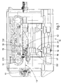
- a continuous drawing device 10 which is substantially known in itself is positioned downstream of a drawbench 11.
- the device 10 comprises two drawing chains 12-112 located on the same plane in the neighbourhood of a drawing axis 13.
- the two chains 12-112 may lie on the same horizontal, vertical or inclined plane, depending on the choice of the design work.
- each chain 12-112 is wound on their respective sprockets 14; each chain comprises an opposed straight segment on the drawing axis 13.
- Each chain 12-112 bears its respective halves of drawing clamps 15-115, which cooperate in forming complete clamps on the drawing axis 13.
- Both the first halves 15 and the second halves 115 of the clamps are connected to their respective chains 12-112 by suitable connection means 16.
- the device 10 is equipped with means to adjust the distance between centres of the chains 12-112.
- the adjustment of the distance between centres is required in the initial drawing step when it is necessary to be able to apply great displacements to the clamps 15-115 at a right angle to the drawing axis 13 so as to enable the operations of introduction and gripping of the material to be drawn to be carried out.
- This adjustment of the distance between centres in a direction at a right angle to the drawing axis 13 is of a modest value but is also required to adapt the chains 12-112 to the variations in the diameters to be drawn.
- the means for adjustment of the distance between centres comprise a motor 17 of a suitable type that actuates a pair of threaded shafts 19 through transmissions 19.
- Each threaded shaft 19 comprises two threaded segments 20-120, one having a righthand thread and the other a lefthand thread, which cooperate with their own nut screw assemblies 21-121 (see Fig.2). These nut screw assemblies 21-121 cooperate with sleeve assemblies 22-122 connected to the respective chains 12-112.
- the sleeve assemblies 22-122 can slide in relation to the coordinated nut screw assemblies 21-121 and, when thrust by the latter 21-121 during rotation of the threaded shafts 19, are displaced.
- one chain 12 is brought, by means of the sleeve assembly 22 connected thereto, to a position orthogonally in relation to the drawing axis 13 by the motor 17; this position is the final one to be taken up by that chain 12 according to the pre-selected diameter to be drawn.
- the other chain 112 is brought at the same time by the other sleeve assembly 122 connected thereto in the opposite direction to that of the first chain 12 to a required position in relation to the drawing axis 13, but this position is not the final position and is distant by a required value from the drawing axis 13.
- the final position of the second chain 112 namely the position for clamping between the two chains 12-112 the material to be drawn, is reached with a supplementary travel of the second sleeve assembly 122.
- This supplementary travel is obtained by the injection of fluid under pressure into a chamber 23 positioned between the second nut screw assembly 121 and the second sleeve assembly 122.
- the fluid under pressure causes the second sleeve assembly 122 to slide in relation to the second nut screw assembly 121 and the second chain 112 to be displaced downwards by a value which corresponds to the play 24 in the embodiment of Fig.2.
- Means 25 and 125 are included to eliminate the mechanical play proper to the system and, in particular, the play in the threaded segments 20-120 and nut screw assemblies 21-121.
Landscapes
- Engineering & Computer Science (AREA)
- Mechanical Engineering (AREA)
- Metal Extraction Processes (AREA)
- Forging (AREA)
- Mechanical Pencils And Projecting And Retracting Systems Therefor, And Multi-System Writing Instruments (AREA)
- Electrical Discharge Machining, Electrochemical Machining, And Combined Machining (AREA)
- Preparing Plates And Mask In Photomechanical Process (AREA)
- Folding Of Thin Sheet-Like Materials, Special Discharging Devices, And Others (AREA)
Applications Claiming Priority (2)
| Application Number | Priority Date | Filing Date | Title |
|---|---|---|---|
| IT8354189 | 1989-12-19 | ||
| IT08354189A IT1236458B (it) | 1989-12-19 | 1989-12-19 | Procedimento di tiro continuo per trafilatura rettilinea e dispositivo adottante tale procedimento. |
Publications (2)
| Publication Number | Publication Date |
|---|---|
| EP0433767A1 EP0433767A1 (en) | 1991-06-26 |
| EP0433767B1 true EP0433767B1 (en) | 1994-09-28 |
Family
ID=11322892
Family Applications (1)
| Application Number | Title | Priority Date | Filing Date |
|---|---|---|---|
| EP90123300A Expired - Lifetime EP0433767B1 (en) | 1989-12-19 | 1990-12-05 | Continuous drawing method for straight drawing operations and device that employs the method |
Country Status (5)
| Country | Link |
|---|---|
| EP (1) | EP0433767B1 (it) |
| AT (1) | ATE112189T1 (it) |
| DE (1) | DE69012966T2 (it) |
| ES (1) | ES2063885T3 (it) |
| IT (1) | IT1236458B (it) |
Cited By (4)
| Publication number | Priority date | Publication date | Assignee | Title |
|---|---|---|---|---|
| DE19708709C1 (de) * | 1997-02-24 | 1998-03-12 | Mannesmann Ag | Antrieb für eine kontinuierliche Ziehvorrichtung zum Geradeausziehen von Rohren oder Stangen |
| DE19727699A1 (de) * | 1997-06-23 | 1998-12-24 | Mannesmann Ag | Ketteneinlauf an Raupenketten-Ziehmaschinen |
| DE19936742A1 (de) * | 1999-08-07 | 2001-02-08 | Schumag Ag | Antrieb für ein Kettenrad, insbesondere einer Kettenziehvorrichtung |
| RU2210444C2 (ru) * | 1996-12-17 | 2003-08-20 | Маннесманн Акциенгезелльшафт | Способ холодного пильгерования труб |
Families Citing this family (7)
| Publication number | Priority date | Publication date | Assignee | Title |
|---|---|---|---|---|
| ES2111225T3 (es) * | 1993-09-29 | 1998-03-01 | Danieli Off Mecc | Maquina para estirar varillas. |
| DE102004023237A1 (de) * | 2004-03-28 | 2005-11-17 | Schumag Ag | Ziehmaschine und Verfahren zum Ziehen eines Ziehgutes |
| CN105665457B (zh) * | 2016-02-29 | 2018-01-23 | 镇江永沃铜业有限公司 | 一种铜棒拉丝机 |
| CN105537299B (zh) * | 2016-02-29 | 2017-11-07 | 镇江永沃铜业有限公司 | 一种自动循坏式铜棒拉丝机 |
| CN105537300B (zh) * | 2016-02-29 | 2017-11-14 | 镇江永沃铜业有限公司 | 一种用于铜棒的自动拉丝装置 |
| CN109877382A (zh) * | 2019-03-22 | 2019-06-14 | 张智林 | 双向连续金属杆拉光机 |
| CN111570546B (zh) * | 2020-06-02 | 2025-03-25 | 烟台孚信达双金属股份有限公司 | 铜铝复合排履带拉拔模具可移动装置 |
Family Cites Families (2)
| Publication number | Priority date | Publication date | Assignee | Title |
|---|---|---|---|---|
| US2642280A (en) * | 1945-10-25 | 1953-06-16 | Gustaf L Fisk | Apparatus for cold reducing metal bars |
| US2797798A (en) * | 1952-07-07 | 1957-07-02 | Hallden Machine Company | Tractor-type stock feed |
-
1989
- 1989-12-19 IT IT08354189A patent/IT1236458B/it active IP Right Grant
-
1990
- 1990-12-05 DE DE69012966T patent/DE69012966T2/de not_active Expired - Lifetime
- 1990-12-05 ES ES90123300T patent/ES2063885T3/es not_active Expired - Lifetime
- 1990-12-05 AT AT90123300T patent/ATE112189T1/de not_active IP Right Cessation
- 1990-12-05 EP EP90123300A patent/EP0433767B1/en not_active Expired - Lifetime
Cited By (4)
| Publication number | Priority date | Publication date | Assignee | Title |
|---|---|---|---|---|
| RU2210444C2 (ru) * | 1996-12-17 | 2003-08-20 | Маннесманн Акциенгезелльшафт | Способ холодного пильгерования труб |
| DE19708709C1 (de) * | 1997-02-24 | 1998-03-12 | Mannesmann Ag | Antrieb für eine kontinuierliche Ziehvorrichtung zum Geradeausziehen von Rohren oder Stangen |
| DE19727699A1 (de) * | 1997-06-23 | 1998-12-24 | Mannesmann Ag | Ketteneinlauf an Raupenketten-Ziehmaschinen |
| DE19936742A1 (de) * | 1999-08-07 | 2001-02-08 | Schumag Ag | Antrieb für ein Kettenrad, insbesondere einer Kettenziehvorrichtung |
Also Published As
| Publication number | Publication date |
|---|---|
| IT8983541A0 (it) | 1989-12-19 |
| ATE112189T1 (de) | 1994-10-15 |
| DE69012966T2 (de) | 1995-02-02 |
| IT8983541A1 (it) | 1991-06-19 |
| EP0433767A1 (en) | 1991-06-26 |
| DE69012966D1 (de) | 1994-11-03 |
| ES2063885T3 (es) | 1995-01-16 |
| IT1236458B (it) | 1993-03-09 |
Similar Documents
| Publication | Publication Date | Title |
|---|---|---|
| US3426569A (en) | Stretch forming machine and segmental adjustable die combination | |
| CN211759238U (zh) | 一种三卡盘激光切管机 | |
| US4178788A (en) | Adjustable clamp die | |
| EP0433767A1 (en) | Continuous drawing method for straight drawing operations and device that employs the method | |
| US4625531A (en) | Bending machine | |
| US4802567A (en) | Plate processing machine | |
| RU2043815C1 (ru) | Прессовый агрегат | |
| CN109396201B (zh) | 一种液压连续拉拔机构及铜合金盘圆表面剥皮系统 | |
| US6038903A (en) | Dual headed bending machine | |
| JPS6210209A (ja) | 高周波焼入のための自動装置 | |
| US2411801A (en) | Metal bending and stretching apparatus | |
| CN112252101A (zh) | 一种钢轨精确对轨装置及其方法 | |
| GB2116091A (en) | Extraction of horizontally cast continuous metal strands | |
| JPH025487B2 (it) | ||
| CA1143189A (en) | Method and apparatus for cold finishing of metals | |
| CN109038175B (zh) | 全自动穿热缩管方法及采用该方法的全自动穿热缩管机 | |
| US4896523A (en) | Finger opening mechanism for transfer press | |
| US3559439A (en) | Arrangement for shaping of profiled curved workpieces from blanks | |
| DE69106708T2 (de) | Biegemaschine. | |
| CN110947806A (zh) | 一种全自动弯管设备和方法 | |
| CN110560524A (zh) | 多半径弯管机 | |
| GB2325630A (en) | Bending apparatus | |
| CN115027066A (zh) | 一种液压软管扣压机 | |
| CN108787824B (zh) | 用于空管花铁架的弯管机 | |
| CN221560190U (zh) | 一种弦梁激光复合焊夹具结构 |
Legal Events
| Date | Code | Title | Description |
|---|---|---|---|
| PUAI | Public reference made under article 153(3) epc to a published international application that has entered the european phase |
Free format text: ORIGINAL CODE: 0009012 |
|
| AK | Designated contracting states |
Kind code of ref document: A1 Designated state(s): AT BE CH DE DK ES FR GB GR LI LU NL SE |
|
| 17P | Request for examination filed |
Effective date: 19911116 |
|
| 17Q | First examination report despatched |
Effective date: 19930209 |
|
| GRAA | (expected) grant |
Free format text: ORIGINAL CODE: 0009210 |
|
| AK | Designated contracting states |
Kind code of ref document: B1 Designated state(s): AT BE CH DE DK ES FR GB GR LI LU NL SE |
|
| PG25 | Lapsed in a contracting state [announced via postgrant information from national office to epo] |
Ref country code: LI Effective date: 19940928 Ref country code: GR Free format text: LAPSE BECAUSE OF FAILURE TO SUBMIT A TRANSLATION OF THE DESCRIPTION OR TO PAY THE FEE WITHIN THE PRESCRIBED TIME-LIMIT Effective date: 19940928 Ref country code: NL Effective date: 19940928 Ref country code: CH Effective date: 19940928 Ref country code: DK Effective date: 19940928 |
|
| REF | Corresponds to: |
Ref document number: 112189 Country of ref document: AT Date of ref document: 19941015 Kind code of ref document: T |
|
| REF | Corresponds to: |
Ref document number: 69012966 Country of ref document: DE Date of ref document: 19941103 |
|
| ET | Fr: translation filed | ||
| PG25 | Lapsed in a contracting state [announced via postgrant information from national office to epo] |
Ref country code: SE Effective date: 19941228 |
|
| PG25 | Lapsed in a contracting state [announced via postgrant information from national office to epo] |
Ref country code: LU Free format text: LAPSE BECAUSE OF NON-PAYMENT OF DUE FEES Effective date: 19941231 |
|
| REG | Reference to a national code |
Ref country code: CH Ref legal event code: PL |
|
| REG | Reference to a national code |
Ref country code: ES Ref legal event code: FG2A Ref document number: 2063885 Country of ref document: ES Kind code of ref document: T3 |
|
| NLV1 | Nl: lapsed or annulled due to failure to fulfill the requirements of art. 29p and 29m of the patents act | ||
| PLBE | No opposition filed within time limit |
Free format text: ORIGINAL CODE: 0009261 |
|
| STAA | Information on the status of an ep patent application or granted ep patent |
Free format text: STATUS: NO OPPOSITION FILED WITHIN TIME LIMIT |
|
| 26N | No opposition filed | ||
| REG | Reference to a national code |
Ref country code: GB Ref legal event code: IF02 |
|
| PGFP | Annual fee paid to national office [announced via postgrant information from national office to epo] |
Ref country code: AT Payment date: 20091124 Year of fee payment: 20 Ref country code: ES Payment date: 20091203 Year of fee payment: 20 |
|
| PGFP | Annual fee paid to national office [announced via postgrant information from national office to epo] |
Ref country code: GB Payment date: 20091125 Year of fee payment: 20 |
|
| PGFP | Annual fee paid to national office [announced via postgrant information from national office to epo] |
Ref country code: FR Payment date: 20100115 Year of fee payment: 20 |
|
| PGFP | Annual fee paid to national office [announced via postgrant information from national office to epo] |
Ref country code: DE Payment date: 20091204 Year of fee payment: 20 Ref country code: BE Payment date: 20091126 Year of fee payment: 20 |
|
| REG | Reference to a national code |
Ref country code: GB Ref legal event code: PE20 Expiry date: 20101204 |
|
| BE20 | Be: patent expired |
Owner name: *DANIELI NATISONE S.P.A. Effective date: 20101205 Owner name: *DANIELI & C. OFFICINE MECCANICHE S.P.A. Effective date: 20101205 |
|
| PG25 | Lapsed in a contracting state [announced via postgrant information from national office to epo] |
Ref country code: GB Free format text: LAPSE BECAUSE OF EXPIRATION OF PROTECTION Effective date: 20101204 |
|
| PG25 | Lapsed in a contracting state [announced via postgrant information from national office to epo] |
Ref country code: DE Free format text: LAPSE BECAUSE OF EXPIRATION OF PROTECTION Effective date: 20101205 |
|
| REG | Reference to a national code |
Ref country code: ES Ref legal event code: FD2A Effective date: 20130725 |
|
| PG25 | Lapsed in a contracting state [announced via postgrant information from national office to epo] |
Ref country code: ES Free format text: LAPSE BECAUSE OF EXPIRATION OF PROTECTION Effective date: 20101206 |