EP0433793B1 - Trockentoilette mit verschliessbarem Behälter zur Aufnahme von Fäkalien - Google Patents
Trockentoilette mit verschliessbarem Behälter zur Aufnahme von Fäkalien Download PDFInfo
- Publication number
- EP0433793B1 EP0433793B1 EP90123524A EP90123524A EP0433793B1 EP 0433793 B1 EP0433793 B1 EP 0433793B1 EP 90123524 A EP90123524 A EP 90123524A EP 90123524 A EP90123524 A EP 90123524A EP 0433793 B1 EP0433793 B1 EP 0433793B1
- Authority
- EP
- European Patent Office
- Prior art keywords
- receptacle
- lid
- container
- toilet
- rim
- Prior art date
- Legal status (The legal status is an assumption and is not a legal conclusion. Google has not performed a legal analysis and makes no representation as to the accuracy of the status listed.)
- Expired - Lifetime
Links
Images



Classifications
-
- A—HUMAN NECESSITIES
- A47—FURNITURE; DOMESTIC ARTICLES OR APPLIANCES; COFFEE MILLS; SPICE MILLS; SUCTION CLEANERS IN GENERAL
- A47K—SANITARY EQUIPMENT; ACCESSORIES THEREFOR, e.g. TOILET ACCESSORIES
- A47K13/00—Seats or covers for all kinds of closets
- A47K13/10—Devices for raising and lowering ; Collapsible or rotating seats or covers
-
- A—HUMAN NECESSITIES
- A47—FURNITURE; DOMESTIC ARTICLES OR APPLIANCES; COFFEE MILLS; SPICE MILLS; SUCTION CLEANERS IN GENERAL
- A47K—SANITARY EQUIPMENT; ACCESSORIES THEREFOR, e.g. TOILET ACCESSORIES
- A47K11/00—Closets without flushing; Urinals without flushing; Chamber pots; Chairs with toilet conveniences or specially adapted for use with toilets
- A47K11/02—Dry closets, e.g. incinerator closets
-
- A—HUMAN NECESSITIES
- A47—FURNITURE; DOMESTIC ARTICLES OR APPLIANCES; COFFEE MILLS; SPICE MILLS; SUCTION CLEANERS IN GENERAL
- A47K—SANITARY EQUIPMENT; ACCESSORIES THEREFOR, e.g. TOILET ACCESSORIES
- A47K11/00—Closets without flushing; Urinals without flushing; Chamber pots; Chairs with toilet conveniences or specially adapted for use with toilets
- A47K11/04—Room closets; Chairs with toilet conveniences or specially adapted for use with toilets, e.g. night chairs ; Closets for children, also with signalling means, e.g. with a music box, or the like
-
- Y—GENERAL TAGGING OF NEW TECHNOLOGICAL DEVELOPMENTS; GENERAL TAGGING OF CROSS-SECTIONAL TECHNOLOGIES SPANNING OVER SEVERAL SECTIONS OF THE IPC; TECHNICAL SUBJECTS COVERED BY FORMER USPC CROSS-REFERENCE ART COLLECTIONS [XRACs] AND DIGESTS
- Y02—TECHNOLOGIES OR APPLICATIONS FOR MITIGATION OR ADAPTATION AGAINST CLIMATE CHANGE
- Y02A—TECHNOLOGIES FOR ADAPTATION TO CLIMATE CHANGE
- Y02A50/00—TECHNOLOGIES FOR ADAPTATION TO CLIMATE CHANGE in human health protection, e.g. against extreme weather
- Y02A50/30—Against vector-borne diseases, e.g. mosquito-borne, fly-borne, tick-borne or waterborne diseases whose impact is exacerbated by climate change
Definitions
- the invention relates to the use of a closable container for holding waste as a dry toilet with a seat.
- Another dry toilet is known from US Pat. No. 3,495,278.
- the container is designed as a flexible bag in this known toilet.
- the toilet seat is provided with a rotating device which can be rotated after the bowel movement with respect to the toilet stool designed as a container, so that the bag filled with the faeces is twisted and thus closes. The twisted and sealed bag can be lifted off and disposed of.
- the user must therefore carry out manipulations in the area of the toilet seat and also pick up and remove the closed bag in the twisting area. It is disadvantageous that when using the toilet in public areas (aircraft, camping, bus) it is not ensured that every user carries out the necessary actions and leaves the next user a clean toilet. It is also uncomfortable to reach into the seating area and to grip the filled bag in the drill area.
- an "abort device” according to DE-U-71 03 988.
- this device there is a seat under which a pit-like chamber is provided, the wall of which is thermally insulated and connected to a cooling system in such a way that cooling of the feces falling into the pit, a bag being provided for transport, which is used as cladding of the pit wall.
- the bag with the frozen, solid faeces is removed and disposed of before thawing.
- a disadvantage of this device is that the heat content of the fresh faeces, which have a temperature of 36 ° C, will quickly consume the cold supply, so that constant post-cooling is required.
- a cooling machine with a loud compressor noise may be very time-consuming, on the other hand, it may be undesirable on campsites. The problem of disposal remains a disgusting activity.
- a dry toilet has been created, which guarantees trouble-free, hygienic operation and as little unpleasant work as possible for the user and waste disposal company.
- a support device is arranged in the recess, which supports the container from below and which is preferably adjustable in the vertical direction.
- the support device can preferably be used to compress the bag so that the container can be downsized before the lid is put on.
- the function is essential that the adjustable support device presses the lid against the upwardly pressing container rim when the toilet seat is lying on it, so that the latching elements penetrate and snap into one another.
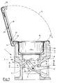
- a dry toilet according to FIGS. 1 to 4 consists of a base 1 designed as a stool, which has the shape of a goblet approximately in section.
- the inside of the base 1 is a cavity 2 accessible from above, in which a support device 3 is installed at about half the height.
- the support device 3 in turn carries a receiving cylinder 4 made of sheet steel, which is closed at the bottom by a steel base 5 and ends at the top in a free edge 6.
- a star-like support 7 is arranged beneath the base 5, which is part of the support device and grips the base 5 from below and can lift it.
- the support 7 ends at the bottom in a bead comb 8 which lies in a groove 9a of a support roller 9 (cf. FIG. 4).
- the support roller 9 is in turn part and end of a toggle lever 10 which is rotatably mounted in a shaft 11.
- the ends of the shaft 11 are supported in recessed shoulders 12a and 12b of the lowermost part 1b of the base.
- the toggle lever 10 can be operated via a pedal 13 and can be pivoted by approximately 30 °.
- the support roller 9 reaches the dashed (upper) position according to FIG. 1 and thus lifts the support 7 and the receiving cylinder 4.
- two coil springs 18, 19 are suspended in the support 7, which are suspended via a bolt 20 or a bore in the toggle lever 10 at the other end and ensure that an upward direction pull is produced which, when the pedal 13 is released, releases the support device 3 with the receiving cylinder 4 and a container 15 pulls down again.
- the container 15 is suspended from plastic film.
- the container 15 has a capacity of about 5 l. It consists of a container body 15a and an upper circumferential collar 16, which is seated on the container body and is firmly connected to it.
- the collar 16 is designed as an everting bead with an upward-facing curvature and has an approximately upside-down shape in cross section "J".
- the everting bead is designated by the reference number 17.
- the collar 16 consists, for example, of an approximately 3-5 mm thick polyethylene torus, while the container body 15a is made of polyethylene film of approximately 1 mm thickness, which is welded to the collar 16.
- the edge 6 of the receiving cylinder 4 lies below the collar 16 and supports it from below.
- the suspended container 15 can also be shifted upwards by a certain amount.
- the base 1 ends at the top in an edge 1a on which a toilet seat 22 is placed.
- the toilet seat 22 has approximately the shape of a circular ring which is open at the bottom and is dimensioned such that the inside bead 17 of the container 15 bears against it. This results in a seat opening modeled on the usual toilet seat for the toilet user.
- the toilet seat 22 is screwed to the base 1 via a locking device 23 and can also be removed from it.
- the locking device 23 engages with a nose in a groove 21 which is formed in the edge 1a.
- a toilet lid 25 is articulated to the left part of the edge 1a in FIG. 1.
- the toilet seat 22 is also designed as a lid holder for a container lid 26.
- the cover 26 also consists of relatively rigid polyethylene and has edge-side slip grooves 27 which are designed as compatible locking elements for the slip bead 17.
- the lid 26 also has a handle that fits snugly in the state shown, so that it cannot be shown in the drawing.
- a snap lock 29 is attached to the front edge of the toilet lid.
- the latch 29, is resiliently mounted on the toilet lid 25, pushed over the outer edge of the locking device 23 and snaps under the nose 23a. It can be swung out again by pushing it out.
- the container lid 26 rests on the container 15 in such a way that the compatible locking and counter elements lie in the immediate contacting neighborhood, but do not snap.
- the container 16, which is filled after a bowel movement, is tightly closed by actuating the pedal 13 when the toilet lid 25 is in place and locked, as a result of which the support device 3 moves upward and presses the everting bead 17 into the corresponding everting groove 27 of the lid 26 from below.
- the lid 26 is a hermetic closure of the container and allows the container to be lifted out of the handle, even if it has become heavy up to 7 kg.
- an inner cover can be used instead of a slip lid, which is equipped in a suitably designed collar, i. H. that this carries, for example, locking lugs as support and locking elements within the container outline.
- the container can be both flexible and relatively stiff and cannot be pressed in. This is primarily a question of cost. Suitable materials are primarily waterproof plastics, but also appropriately coated papers and similar, disposable materials.
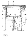
- a lever adjustment device designated by the reference number 40, is provided as the support device, which is connected at one end to a rod 43 mounted in a sleeve guide 42.
- a rod 43 mounted in a sleeve guide 42.
- two disks 44 spaced one above the other and 45 attached concentrically to the rod.
- the upper disc which closes the rod head, has a smaller diameter, while the lower disc 44 has a larger diameter.
- a receiving cylinder 47 made of stainless steel runs down into a flange-like ring rim 48 which surrounds a large opening 49 in the center.
- the diameter of the upper disk 45 is smaller than the clear width of the opening 49, while the diameter of the larger disk 44 is larger than this clear width.
- Inside the cylinder 47 is a cup-shaped, elastic
- Rubber membrane 50 used so that it fills the inside of the pot and covers the opening 49 with its bottom.
- the deformation resistance of the rubber membrane in the area of the opening 49 is so great that when the receiving cylinder 47 is empty or filled (rubber-lined), the opening 49 is tightly spanned, i.e. the rubber membrane is hardly pressed in there.
- the receiving cylinder 47 is carried by the small disk 45.
- the container provided with a rigid lid rim which is a bag in the usual sense, is hung.
- the toilet lid is closed and locked, as has already been described.
- the lever 41 moves and pushes the rod 43 upwards.
- the smaller disk 45 comes into firm contact with the rubber floor 51 in the region of the opening 49 and presses the receiving cylinder 47 upwards until it comes into contact with the toilet lid 26.
- the cover 26 is slipped inside over the small disk 45, to the extent that the large disk 44 comes into contact with the ring edge 48 of the receiving cylinder 47 and thus the relative movement of the rod 43 to the receiving cylinder 47 has an end.
- the edge of the bag is then pressed into the corresponding compatible elements of the lid 26, so that the bag (container 15) and lid 26 snap together.
- This latching operation is accordingly a restriction of the volume of the container 15, since the upper disk 44 can be pushed in through the limited opening 49 while deforming the membrane 50 until the lower disk 45 abuts the ring rim 48 from below.
- the aforementioned solution represents a possibility of reducing the volume of the suspended container 15 before the cover is pressed on.
- This technical variant can also be carried out differently with similar stacking devices.
- the squeezing of the container also has the advantage that, in the case of possible fermentation processes, the resulting gas initially fills the pressed-in volume and does not cause the container 15 to burst.
Landscapes
- Health & Medical Sciences (AREA)
- Public Health (AREA)
- Non-Flushing Toilets (AREA)
- Packages (AREA)
Description
- Die Erfindung betrifft die Verwendung eines verschließbaren Behälters zur Aufnahme von Abfällen als Trockentoilette mit Sitz.
- Aus der Schrift WO 88/03416 ist eine Vorrichtung zur hygienischen Abfallaufnahme bekannt, mit folgenden Elementen:
- einem Behälter, der von einer Haltevorrichtung getragen und mit einem Deckel verschließbar ist, wobei der Deckel auf den Kragen des Behälters, der auf seinem Umfang Rastelemente aufweist, aufgesetzt wird,
- zu den Rastelementen des Kragens kompatible Gegenelemente, mit denen der Deckel verrsehen ist,
- wobei Rast- und Gegenelemente festsitzend zu verbinden sind und nach dem Einrasten des Deckels einen hermetischen Verschluß des Behälters ergeben und ein Herausheben des Behälters unter Ergreifen des Deckels ermöglichen.
- Nach der Erfindung ist die Verwendung des aus der vorgenannten Schrift WO 88/03417 bekannten, verschließbaren Behälters als Trockentoilette mit Sitz vorgesehen. Dabei kommt der bei dem Behälter vorhandene Kragen während des Stuhlgangs im Bereich des Toilettensitzes zu liegen. Der Behälter ist nach dem Stuhlgang aus dem Toilettensitz entnehmbar und verschlossen ablegbar ist. Analog zu dem eingangs beschriebenen Behälter nach dem Stande der Technik besitzt nunmehr die Trockentoilette folgende Elemente:
- Rastelemente auf dem Umfang des Kragens;
- einen Deckel, mit dem der Behälter nach dem Stuhlgang verschließbar ist und der mit zu den Rastelementen des Kragens kompatiblen Gegenelementen versehen ist,
- wobei Rast- und Gegenelemente festsitzend zu verbinden sind und nach dem Einrasten des Deckels einen hermetischen Verschluß des Behälters ergeben und ein Herausheben des Behälters unter Ergreifen des Deckels ermöglichen,
- und die Toilette eine als Schemel gestaltete Basis mit einem von oben zugänglichen Hohlraum besitzt, die vom Toilettensitz wenigstens teilweise umgeben ist und in die der Behälter eingestellt bzw. eingehängt werden kann,
- und mit einer unterhalb des Behälters angeordneten Supportvorrichtung, die den Behälter von unten stutzt und die in vertikaler Richtung verstellbar ist.
- Eine weitere Trockentoilette ist aus der US-PS 3 495 278 bekannt. Der Behälter ist bei dieser bekannten Toilette als flexibler Beutel gestaltet. Der Toilettensitz ist mit einer Drehvorrichtung versehen, die nach dem Stuhlgang gegenüber dem als Umbehälter gestalteten Toilettenschemel verdrehbar ist, so daß sich der mit den Fäkalien gefüllte Beutel verdrillt und damit verschließt. Der verdrillte und verschlossene Beutel kann abgehoben werden und einer Entsorgung zugeführt werden.
- Der Benutzer muß demnach im Bereich des Toilettensitzes Manipulationen durchführen und auch den geschlossenen Beutel im Verdrillungsbereich aufnehmen und entfernen. Dabei ist nachteilig, daß bei einem Einsatz der Toilette im öffentlichen Bereich (Flugzeug, Camping, Bus) nicht sichergestellt ist, daß jeder Benutzer die notwendigen Handgriffe ausführt, und dem nachfolgenden Benutzer eine saubere Toilette hinterläßt. Außerdem ist es unangenehm, in den Sitzbereich hineinzugreifen und den gefüllten Beutel im Drillbereich zu ergreifen.
- Es sei weiterhin verwiesen auf eine "Abort-Vorrichtung" gemäß DE-U-71 03 988. Bei dieser Vorrichtung ist ein Sitz vorhanden, unter dem eine grubenartige Kammer vorgesehen ist, deren Wandung wärmeisoliert und derart mit einem Kühlsystem verbunden ist, daS eine Kühlung der in die Grube fallenden Fäkalien erfolgt, wobei zum Transport ein Beutel vorgesehen ist, der als Verkleidung der Gruben-Wandung eingesetzt wird. Der Beutel mit den tiefgefrorenen, festen Fäkalien wird entnommen und vor dem Auftauen entsorgt. Nachteilig bei dieser Vorrichtung ist, daß der Wärmeinhalt der frischen Fäkalien, die eine Temperatur von 36°C haben, den Kältevorrat rasch verbrauchen werden, so daß ein ständiges Nachkühlen erforderlich ist. Eine Kühlmaschine mit lautem Kompressorgeräusch dürfte aber einmal sehr aufwendig sein, zum anderen auf Camping-Plätzen unerwünscht sein. Das Problem der Entsorgung bleibt weiterhin eine ekelerregende Tätigkeit.
- Die Nachteile des Standes der Technik werden bei der Erfindung vermieden; es ist eine Trockentoilette geschaffen, die einen störungsfreien, hygienischen Betrieb gewährleistet und dem Benutzer und Entsorger möglichst wenige unangenehme Arbeiten zumutet.
- Um das Aufsetzen des Deckels zu erleichtern, wird in der Vertiefung eine Supportvorrichtung angeordnet, die den Behälter von unten stützt und die vorzugsweise in vertikaler Richtung verstellbar ist.
- Vorteilhaft ist weiterhin, daß mit Hilfe der Supportvorrichtung vorzugsweise der Beutel zusammengedrückt werden kann, so daß der Behälter vor dem Aufsetzen des Deckels verkleinerbar ist.
- Wesentlich ist insgesamt die Funktion, daß durch die verstellbare Supportvorrichtung bei aufliegendem Toilettensitz der Deckel gegen den nach oben drückenden Behälterrand aufgedrückt wird, so daß die Rastelemente ineinander dringen und rasten.
- Merkmale weiterer Unteransprüche werden in der nachfolgenden Beschreibung erläutert.
- Die Beschreibung erfolgt anhand einer Zeichnung. Die Figuren der Zeichnung zeigen im einzelnen:
- Figur 1
- eine Seitenansicht einer Trockentoilette in einer ersten Ausführungsform, mit geöffnetem Toilettendeckel;
- Figur 2
- eine Seitenansicht der Trockentoilette gemäß Figur 1, mit geschlossenem Toilettendeckel;
- Figur 3
- einen Schnitt gemäß der Linie A - B der Figur 1;
- Figur 4
- eine Vorderansicht der Trockentoilette gemäß Figur 1 im Schnitt;
- Figuren 5 und 6
- ähnliche Ansichten wie Figuren 1 bzw. 2, jedoch einer anderen Ausführungsform.
- Eine Trockentoilette gemäß den Figuren 1 bis 4 besteht aus einer als Schemel gestalteten Basis 1, die etwa im Schnitt die Form eines Kelches hat. Das Innere der Basis 1 ist ein von oben zugänglicher Hohlraum 2, in den auf etwa halber Höhe eine Supportvorrichtung 3 eingebaut ist. Die Supportvorrichtung 3 wiederum trägt einen Aufnahmezylinder 4 aus Stahlblech, der unten durch einen stählernen Boden 5 geschlossen ist und nach oben in einem freien Rand 6 endet. Unterhalb des Bodens 5 ist eine sternartige Stütze 7 angeordnet, die Teil der Supportvorrichtung ist und den Boden 5 von unten unterfaßt und ihn anheben kann. Die Stütze 7 endet nach unten in einem Wulstkamm 8, der in eine Nut 9a einer Tragrolle 9 liegt (vgl. Fig. 4). Die Tragrolle 9 wiederum ist Teil und Ende eines Kniehebels 10, der in einer Welle 11 drehbar gelagert ist. Die Enden der Welle 11 sind in einspringenden Schultern 12a und 12b des untersten Teils 1b der Basis gelagert.
- Der Kniehebel 10 ist über ein Pedal 13 zu betätigen und um etwa 30° verschwenkbar. Beim Niederdrücken des Pedals 13 gelangt die Tragrolle 9 in die gestrichelte (obere) Stellung gemäß Figur 1 und hebt damit die Stütze 7 und den Aufnahmezylinder 4 an. Weiterhin sind in die Stütze 7 zwei Spiralfedern 18, 19 eingehängt, die über einen Bolzen 20 bzw. eine Bohrung im Kniehebel 10 anderen Endes aufgehängt sind und dafür sorgen, daß ein der Aufwärtsrichtung entgegengesetzter Zug hervorgerufen wird, der bei Loslassen des Pedals 13 die Supportvorrichtung 3 mit dem Aufnahmezylinder 4 und einem Behälter 15 wieder nach unten zieht.
- In den Aufnahmezylinder 4 ist der Behälter 15 aus Kunststoff-Folie eingehängt. Der Behälter 15 besitzt ein Fassungsvermögen von etwa 5 l. Er besteht aus einem Behälterkörper 15a und einem oberen, auf dem Behälterkörper aufsitzenden und mit diesem fest verbundenen, umlaufenden Kragen 16. Der Kragen 16 ist als Stülpwulst mit nach oben zeigender Rundung gestaltet und hat im Querschnitt etwa die Form eines auf dem Kopf stehenden "J". Der Stülpwulst ist hierbei mit der Bezugszahl 17 bezeichnet. Der Kragen 16 besteht beispielsweise aus einem etwa 3 - 5 mm dicken Polyethylen-Torus, während der Behälterkörper 15a aus Polyethylenfolie von etwa 1 mm Dicke gefertigt ist, die mit dem Kragen 16 verschweißt ist. Wie aus der Figur erkennbar ist, liegt der Rand 6 des Aufnahmezylinders 4 unterhalb des Kragens 16 und stützt diesen von unten. Auch ist der eingehängte Behälter 15 um einen gewissen Betrag nach oben verschiebbar.
- Nach oben hin endet die Basis 1 in einem Rand 1a, auf den ein Toilettensitz 22 aufgelegt ist. Der Toilettensitz 22 hat etwa die Form eines nach unten offenen Kreisringes und ist so bemessen, daß an seiner Innenseite der Stülpwulst 17 des Behälters 15 anliegt. Somit ergibt sich eine den üblichen Toilettenbrillen nachempfundene Sitzöffnung für den Toilettenbenutzer. Der Toilettensitz 22 ist über eine Feststellvorrichtung 23 an die Basis 1 angeschraubt und von ihr auch wieder abnehmbar. Die Feststellvorrichtung 23 greift mit einer Nase in eine Nut 21, die in dem Rand 1a ausgebildet ist.
- An den in der Figur 1 linken Teil des Randes 1a ist ein Toilettendeckel 25 angelenkt. Der Toilettensitz 22 ist gleichzeitig als ein Deckelhalter für einen Behälter-Deckel 26 gestaltet. Der Deckel 26 besteht ebenfalls aus relativ steifen Polyethylen und besitzt randseitige Stülpnuten 27, die als kompatible Rastelemente für den Stülpwulst 17 ausgebildet sind. Der Deckel 26 besitzt ferner noch einen Handgriff, der im dargestellten Zustand eng anliegt, so daß er in der Zeichnung nicht darstellbar ist. Am vorderen Rand des Toilettendeckels ist ein Schnappriegel 29 angebracht.
- Beim Herunterschwenken des Toilettendeckels 25 gemäß der gestrichelten Drehlinie D wird der Schnappriegel 29, der federnd am Toilettendeckel 25 gelagert ist, über den äußeren Rand der Feststellvorrichtung 23 geschoben und schnappt unterhalb der Nase 23a ein. Durch Herausdrücken kann er wieder herausgeschwenkt werden. In der SchließStellung des Toilettendeckels 25 liegt demnach der Behälter-Deckel 26 so auf dem Behälter 15 auf, daß die kompatiblen Rast- und Gegenelemente in unmittelbarer kontaktierender Nachbarschaft liegen, aber nicht rasten. Der nach einem Stuhlgang gefüllte Behälter 16 wird fest verschlossen, indem bei aufgelegtem und arretiertem Toilettendeckel 25 das Pedal 13 betätigt wird, wodurch sich die Supportvorrichtung 3 nach oben bewegt und den Stülpwulst 17 von unten in den entsprechenden Stülpnut 27 des Deckels 26 eindrückt. Nach diesem Rastvorgang ist der Deckel 26 ein hermetischer Verschluß des Behälters und erlaubt das Herausheben des Behälters, auch wenn dieser bis zu 7 kg schwer geworden ist, am Handgriff.
- Es wird aus der vorstehenden Beschreibung deutlich, daß anstelle eines Stülpdeckels auch ein Inhendeckel verwendet werden kann, der in einen entsprechend ausgestalteten Kragen ausgerüstet ist, d. h. daß dieser beispielsweise Rastnasen als Auflage- und Rastelemente innerhalb des Behälterumrisses trägt. Der Behälter kann sowohl flexibel sein, als auch relativ steif und nicht eindrüokbar. Dies ist in erster Linie eine Kostenfrage. Als Material eignen sich in erster Linie wasserfeste Kunststoffe, aber auch entsprechend beschichtete Papiere und ähnliche, disposable Materialien.
- In Figuren 5 und 6 ist eine andere Ausführungsform dargestellt. Bei dieser Ausführungsform ist als Supportvorrichtung eine Hebel-Verstellvorrichtung, bezeichnet mit der Bezugszahl 40, vorgesehen, die einen Endes mit einer in einer Hülsenführung 42 gelagerten Stange 43 verbunden ist. Am oberen Ende der Stange 43 sind zwei im Abstand übereinander liegender Scheiben 44 und 45 konzentrisch zur Stange angebracht. Die obere Scheibe, die den Stangenkopf abschließt, hat einen kleineren Durchmesser, während die untere Scheibe 44 einen größeren Durchmesser besitzt. Ein Aufnahmezylinder 47 aus Edelstahl läuft nach unten in einen flanschartigen Ringrand 48 aus, der mittig eine große Öffnung 49 umschließt. Der Durchmesser der oberen Scheibe 45 ist kleiner als die lichte Weite der Öffnung 49, während der Durchmesser der größeren Scheibe 44 größer ist als diese lichte Weite. Im inneren des Zylinders 47 ist eine topfförmige, elastische
- Gummimenbran 50 so eingesetzt, daß sie das Topfinnere ausfüllt und die Öffnung 49 mit ihrem Boden überdeckt. Der Verformungswiderstand der Gummimenbran im Bereich der Öffnung 49 ist so groß, daß bei leerem oder gefülltem (gummigefüttertem) Aufnahmezylinder 47 die Öffnung 49 straff überspannt ist, d.h., die Gummimenbran dort kaum eingedrückt ist.
- In diesem Bereich wird der Aufnahmezylinder 47 von der kleinen Scheibe 45 getragen. In das Innere des gummigefütterten Zylinders wird, wie bereits am ersten Ausführungsbeispiel beschrieben, der mit einem steifen Deckelrand versehene Behälter, der im üblichen Sinne ein Beutel ist, eingehängt.
- Nach dem Stuhlgang wird der Toilettendeckel geschlossen und gerastet, wie dies bereits beschrieben worden ist. Durch Druck auf das Pedal 13 verstellt sich der Hebel 41 und drückt die Stange 43 nach oben. Dabei kommt die kleinere Scheibe 45, falls noch nicht geschehen, fest in Kontakt mit dem Gummiboden 51 im Bereich der Öffnung 49 und drückt über diesen den Aufnahmezylinder 47 nach oben, bis er in Kontakt mit dem Toilettendeckel 26 kommt. Nach dieser Phase wird über die kleine Scheibe 45 der Deckel 26 nach innen gestülpt, und zwar soweit, bis die große Scheibe 44 mit dem Ringrand 48 des Aufnahmezylinders 47 in Kontakt kommt und damit die Relativbewegung der Stange 43 zu dem Aufnahmezylinder 47 ein Ende hat. Mit weiterer Kraft wird dann der Beutelrand in die entsprechenden kompatiblen Elemente des Deckels 26 eingedrückt, so daß Beutel (Behälter 15) und Deckel 26 miteinander rasten. Diesem Rastvorgang vorangehend ist demnach eine Einschränkung des Volumens des Behälters 15, da die obere Scheibe 44 durch die begrenzte Öffnung 49 unter Verformung der Membran 50 einrückbar ist, bis die untere Scheibe 45 von unten gegen den Ringrand 48 stößt.
- Die vorgenannte Lösung stellt eine Möglichkeit dar, das Volumen des eingehängten Behälters 15 vor dem Aufdrücken des Deckels zu verkleinern. Mit ähnlichen Stapelvorrichtungen läßt sich diese technische Variante auch anders ausführen. Das Zusammendrücken des Behälters hat außerdem den Vorteil, daß bei eventuellen Gärvorgängen das entstehende Gas das eingedrückte Volumen zunächst ausfüllt und nicht etwa den Behälter 15 zum Platzen bringt.
Claims (11)
- Verwendung eines verschließbaren Behälters zur Aufnahme von Abfällen als Trockentoilette mit Sitz, wobei der bei dem Behälter vorhandene Kragen während des Stuhlgangs im Bereich des Toilettensitzes zu liegen kommt und der Behälter nach dem Stuhlgang aus dem Toilettensitz entnehmbar und verschlossen ablegbar ist, mit folgenden Elementen:- Rastelementen (17, 27) auf dem Umfang des Kragens (16);- einem Deckel (26), mit dem der Behälter (15) nach dem Stuhlgang verschließbar ist und der mit zu den Rastelementen des Kragens (16) kompatiblen Gegenelementen versehen ist,- wobei Rast- und Gegenelemente (17, 27) festsitzend zu verbinden sind und nach dem Einrasten des Deckels (26) einen hermetischen Verschluß des Behälters (15) ergeben und ein Herausheben des Behälters (15) unter Ergreifen des Deckels (26) ermöglichen,- und die Toilette eine als Schemel gestaltete Basis (1) mit einem von oben zugänglichen Hohlraum (2) besitzt, die vom Toilettensitz (22) wenigstens teilweise umgeben ist und in die der Behälter (15) eingestellt bzw. eingehängt werden kann,- und mit einer unterhalb des Behälters (15) angeordneten Supportvorrichtung (3, 40), die den Behälter (15) von unten stützt und die in vertikaler Richtung verstellbar ist.
- Verwendung eines Behälters als Trockentoilette nach Anspruch 1, dadurch gekennzeichnet, daß die Supportvorrichtung (3, 40) den Behälter unterhalb von dessen Kragen (16) trägt und stützt.
- Verwendung eines Behälters als Trockentoilette nach Anspruch 1 oder 2, dadurch gekennzeichnet, daß ein den Toilettensitz abdeckender, schwenkbarer Deckel [Toilettendeckel (25)] vorgesehen ist, der auf seiner Innenseite den Deckel (26) freigebbar trägt.
- Verwendung eines Behälters als Trockentoilette nach Anspruch 1 bis 2, dadurch gekennzeichnet, daß ein steifer Aufnahmezylinder (4, 47) auf der Supportvorrichtung (3, 40) aufsteht, in den der Behälter (16) eingestellt oder eingehängt ist.
- Verwendung eines Behälters als Trockentoilette nach Anspruch 4, dadurch gekennzeichnet, daß bei vertikaler Verstellung des Behälters (16) und bei herabgeschwenktem Toilettendeckel (25) die Rast- und Gegenelemente von Behälter-Deckel (26) und Behälterrand ineinander stoßen und einrasten.
- Verwendung eines Behälters als Trockentoilette nach Anspruch 5, dadurch gekennzeichnet, daß der Deckel (26) als Stülpdeckel gestaltet ist und daß eine Stülpwulst (17) am Behälterrand (Kragen 16) als Rastelement vorhanden ist.
- Verwendung eines Behälters als Trockentoilette nach Anspruch 5, dadurch gekennzeichnet, daß der Deckel (26) als Innendeckel gestaltet ist, der in den Kragen (16) einlegbar ist, und daß Rastnasen als Auflage- und Rastelemente innerhalb des Behälters angeordnet sind.
- Verwendung eines Behälters als Trockentoilette nach einem der vorhergehenden Ansprüche, dadurch gekennzeichnet, daR der Behälter (15) aus einer flexiblen Kunststoffolie und der Deckel (26) und der Kragen (16) des Behälters (15) aus einem relativ steifen Material bestehen, verglichen mit dem Material des Behälters (15).
- Verwendung eines Behälters als Trockentoilette wenigstens nach Anspruch 8, dadurch gekennzeichnet, daß mit Hilfe der Supportvorrichtung (3, 40) der Behälter (15) zusammendrückbar ist.
- Verwendung eines Behälters als Trockentoilette nach einem der vorhergehenden Ansprüche 4 bis 9, dadurch gekennzeichnet, daR der Aufnahmezylinder (47) nach unten eine durch einen Flanschrand (48) begrenzte Öffnung (49) besitzt, die durch eine gummielastische Membram (50) abdeckbar ist,
und daß die Supportvorrichtung (3) eine obere kleine und eine im Abstand dazu stehende größere untere Scheibe (45 bzw. 44) aufweist,
wobei die obere Scheibe (45) durch die begrenzte Öffnung (49) unter Verformung der Membran (50) einrückbar ist, bis die untere Scheibe (44) von unten gegen den Flanschrand (48) stößt. - Verwendung eines Behälters als Trockentoilette nach nach einem der vorhergehenden Ansprüche 1 bis 10, gekennzeichnet durch ein an der Unterseite der Supportvorrichtung (3) angreifendes Ende (Rolle 9) einer pedalbetätigbaren Hebelvorrichtung (10), die die Vertikalbewegung des Behälters (15) ermöglicht.
Applications Claiming Priority (2)
| Application Number | Priority Date | Filing Date | Title |
|---|---|---|---|
| DE3941939A DE3941939A1 (de) | 1989-12-19 | 1989-12-19 | Trockentoilette mit verschliessbarem behaelter zur aufnahme von faekalien |
| DE3941939 | 1989-12-19 |
Publications (2)
| Publication Number | Publication Date |
|---|---|
| EP0433793A1 EP0433793A1 (de) | 1991-06-26 |
| EP0433793B1 true EP0433793B1 (de) | 1994-11-30 |
Family
ID=6395812
Family Applications (1)
| Application Number | Title | Priority Date | Filing Date |
|---|---|---|---|
| EP90123524A Expired - Lifetime EP0433793B1 (de) | 1989-12-19 | 1990-12-07 | Trockentoilette mit verschliessbarem Behälter zur Aufnahme von Fäkalien |
Country Status (6)
| Country | Link |
|---|---|
| US (1) | US5177819A (de) |
| EP (1) | EP0433793B1 (de) |
| AT (1) | ATE114434T1 (de) |
| DE (2) | DE3941939A1 (de) |
| DK (1) | DK0433793T3 (de) |
| ES (1) | ES2064592T3 (de) |
Families Citing this family (6)
| Publication number | Priority date | Publication date | Assignee | Title |
|---|---|---|---|---|
| AT400663B (de) * | 1992-09-16 | 1996-02-26 | Oesterreichische Raumfahrt Und | Verschliessbarer behälter für eine trockentoilette sowie trockentoilette |
| ES2210357T3 (es) * | 1996-04-24 | 2004-07-01 | Englong He | Retrete sin agua completamente automatico. |
| SE526298C2 (sv) * | 2002-07-23 | 2005-08-16 | Separett Ab | Tredelad urinseparerande torrtoalett |
| ITCT20060005U1 (it) * | 2006-03-09 | 2006-06-08 | Commerciale Sicula Srl | Sedia wc a secco |
| US9144353B2 (en) * | 2009-03-11 | 2015-09-29 | Franklin Irizarry-Lugo | Waterless air suction toilet |
| USD1021019S1 (en) * | 2021-03-04 | 2024-04-02 | Ali Muthyib Doghim Alsubaie | Toilet |
Family Cites Families (22)
| Publication number | Priority date | Publication date | Assignee | Title |
|---|---|---|---|---|
| DE7103988U (de) * | 1972-05-04 | Tebe-Elprod Ab | Abort-Einrichtung | |
| DE7205756U (de) * | 1972-05-04 | Lilie W | Behälter, insbesondere zur Verwendung als chemische Toilette | |
| DE468100C (de) * | 1927-01-22 | 1928-11-06 | Hermann Flamm Dr | Faekaliengefaess fuer Schwerkranke |
| US2376036A (en) * | 1944-05-26 | 1945-05-15 | Cotton Lucy | Collapsible commode |
| DE823923C (de) * | 1948-10-20 | 1951-12-06 | Wilhelm Konejung | Hocker |
| US2866980A (en) * | 1953-10-19 | 1959-01-06 | Lillian J Huntington | Toilet |
| FR1174621A (fr) * | 1957-05-07 | 1959-03-13 | Vase pour bébés et jeunes enfants | |
| US2956851A (en) * | 1957-06-18 | 1960-10-18 | Yale & Towne Mfg Co | Toothbrush holder |
| US3063061A (en) * | 1960-12-19 | 1962-11-13 | Wallace H Bertram | Portable toilet |
| US3430269A (en) * | 1966-11-03 | 1969-03-04 | Sani Jon Of America Inc | Portable toilet |
| US3495278A (en) * | 1967-06-12 | 1970-02-17 | Alfred H Peters | Disposable bag toilet |
| FR2098909A5 (de) * | 1970-07-22 | 1972-03-10 | David Georges | |
| US3881868A (en) * | 1974-03-06 | 1975-05-06 | Edna Mae Duke | Toothbrush holder and sterilizer |
| US4621380A (en) * | 1982-09-27 | 1986-11-11 | Richard G. Kinney | Toilet assemblies |
| DE3246187C2 (de) * | 1982-12-14 | 1986-07-24 | DATA-LÖSCH Gesellschaft für Sicherheitstechniken im Datenschutz mbH, 4420 Coesfeld | Aufnahmegehäuse für Sicherheits-Einwegbehältnisse |
| SE459633B (sv) * | 1984-11-30 | 1989-07-24 | Bo Grenthe | Torrtoalett |
| DK153437C (da) * | 1985-08-12 | 1988-12-12 | Bente Merrild | Hygiejnisk engangsdaekke til toiletsaeder |
| EP0327562A4 (de) * | 1986-10-20 | 1990-04-10 | Ian F Douglas | Tragbare toilette ohne spülung. |
| WO1988003416A1 (fr) * | 1986-11-14 | 1988-05-19 | Loebbert Johannes | Dispositif pour la collecte hygienique des dechets dans les hopitaux, laboratoires et etablissements similaires |
| US4760613A (en) * | 1988-01-04 | 1988-08-02 | Incorema | Hygienic toilet seat assembly |
| US5074500A (en) * | 1989-06-09 | 1991-12-24 | Johannes Loebbert | Bin with a bin collar and lid |
| US4927011A (en) * | 1989-11-06 | 1990-05-22 | Wilkinson William T | Storage device for personal dental hygiene and oral care products |
-
1989
- 1989-12-19 DE DE3941939A patent/DE3941939A1/de active Granted
-
1990
- 1990-12-07 DK DK90123524.2T patent/DK0433793T3/da active
- 1990-12-07 EP EP90123524A patent/EP0433793B1/de not_active Expired - Lifetime
- 1990-12-07 AT AT90123524T patent/ATE114434T1/de not_active IP Right Cessation
- 1990-12-07 ES ES90123524T patent/ES2064592T3/es not_active Expired - Lifetime
- 1990-12-07 DE DE59007852T patent/DE59007852D1/de not_active Expired - Fee Related
- 1990-12-19 US US07/629,878 patent/US5177819A/en not_active Expired - Lifetime
Also Published As
| Publication number | Publication date |
|---|---|
| ATE114434T1 (de) | 1994-12-15 |
| DE59007852D1 (de) | 1995-01-12 |
| DE3941939A1 (de) | 1991-06-20 |
| DE3941939C2 (de) | 1992-07-23 |
| ES2064592T3 (es) | 1995-02-01 |
| DK0433793T3 (da) | 1995-05-08 |
| US5177819A (en) | 1993-01-12 |
| EP0433793A1 (de) | 1991-06-26 |
Similar Documents
| Publication | Publication Date | Title |
|---|---|---|
| EP0290538B1 (de) | Vorrichtung zur hygienischen abfallaufnahme in krankenhäusern, laboratorien und ähnlichen instituten | |
| DE69201237T2 (de) | Filtereinsatz für behälter. | |
| EP2496118A2 (de) | Teebereiter mit verschliessbarer ausgiessöffnung | |
| DE29918687U1 (de) | Abfallsammler | |
| EP0382001B1 (de) | Vorrichtung zum Zubereiten heisser Getränke | |
| DE9015190U1 (de) | Müllbehälter mit durch Pedal bedienbarem Klappdeckel | |
| EP0433793A1 (de) | Trockentoilette mit verschliessbarem Behälter zur Aufnahme von Fäkalien | |
| EP0401494B1 (de) | Sack mit Sackkragen und Deckel | |
| DE2252927C2 (de) | Vorrichtung zum Verschließen von Schalen mit Aluminiumfolie o.dgl | |
| EP0887038B1 (de) | Ausgiessbares Thermosgefäss | |
| DE2658295C3 (de) | Kaffeekanne, insbesondere zur Verwendung in einer elektrischen Kaffeemaschine | |
| DE8527501U1 (de) | Desinfiziergerät für Toilettenbecken | |
| DE3313366C2 (de) | ||
| DE2611604C2 (de) | Vorrichtung zur Begrenzung des Wasserauslaufes aus Wasserbehältern mit einem Bodenauslauf | |
| DE69501738T2 (de) | Sanitäreinheit (topfchen) | |
| DE3347713A1 (de) | Verschlussanordnung fuer ein gefaess | |
| DE7907722U1 (de) | Abfallpresse | |
| DE3508617C1 (de) | Isolierkanne | |
| DE3015952A1 (de) | Arbeitsplatte, beispielsweise spueltischabdeckung | |
| DE1074487B (de) | ||
| DE68911105T2 (de) | Heizgerät für Dental-Abformmassen. | |
| JPH0538666Y2 (de) | ||
| EP3603459B1 (de) | Getränkebehältnis, insbesondere getränkeflasche, getränkekarton oder getränkedose, mit einem trinkhalm, der zur regulierung der zuflussmenge eingerichtet ist | |
| CH342153A (de) | Hermetisch schliessende Dose | |
| DE1909545A1 (de) | Zahnprothesendose |
Legal Events
| Date | Code | Title | Description |
|---|---|---|---|
| PUAI | Public reference made under article 153(3) epc to a published international application that has entered the european phase |
Free format text: ORIGINAL CODE: 0009012 |
|
| AK | Designated contracting states |
Kind code of ref document: A1 Designated state(s): AT BE CH DE DK ES FR GB GR IT LI LU NL SE |
|
| 17P | Request for examination filed |
Effective date: 19911223 |
|
| 17Q | First examination report despatched |
Effective date: 19930513 |
|
| GRAA | (expected) grant |
Free format text: ORIGINAL CODE: 0009210 |
|
| AK | Designated contracting states |
Kind code of ref document: B1 Designated state(s): AT BE CH DE DK ES FR GB GR IT LI LU NL SE |
|
| REF | Corresponds to: |
Ref document number: 114434 Country of ref document: AT Date of ref document: 19941215 Kind code of ref document: T |
|
| PG25 | Lapsed in a contracting state [announced via postgrant information from national office to epo] |
Ref country code: LU Free format text: LAPSE BECAUSE OF NON-PAYMENT OF DUE FEES Effective date: 19941231 |
|
| REF | Corresponds to: |
Ref document number: 59007852 Country of ref document: DE Date of ref document: 19950112 |
|
| ITF | It: translation for a ep patent filed | ||
| EAL | Se: european patent in force in sweden |
Ref document number: 90123524.2 |
|
| REG | Reference to a national code |
Ref country code: ES Ref legal event code: FG2A Ref document number: 2064592 Country of ref document: ES Kind code of ref document: T3 |
|
| GBT | Gb: translation of ep patent filed (gb section 77(6)(a)/1977) |
Effective date: 19950109 |
|
| ET | Fr: translation filed | ||
| REG | Reference to a national code |
Ref country code: GR Ref legal event code: FG4A Free format text: 3014656 |
|
| REG | Reference to a national code |
Ref country code: DK Ref legal event code: T3 |
|
| PLBE | No opposition filed within time limit |
Free format text: ORIGINAL CODE: 0009261 |
|
| STAA | Information on the status of an ep patent application or granted ep patent |
Free format text: STATUS: NO OPPOSITION FILED WITHIN TIME LIMIT |
|
| 26N | No opposition filed | ||
| REG | Reference to a national code |
Ref country code: GB Ref legal event code: 746 Effective date: 19951116 |
|
| REG | Reference to a national code |
Ref country code: GB Ref legal event code: 746 Effective date: 19960214 |
|
| REG | Reference to a national code |
Ref country code: FR Ref legal event code: D6 |
|
| REG | Reference to a national code |
Ref country code: GB Ref legal event code: IF02 |
|
| PGFP | Annual fee paid to national office [announced via postgrant information from national office to epo] |
Ref country code: GB Payment date: 20060428 Year of fee payment: 16 Ref country code: ES Payment date: 20060428 Year of fee payment: 16 |
|
| PGFP | Annual fee paid to national office [announced via postgrant information from national office to epo] |
Ref country code: SE Payment date: 20060512 Year of fee payment: 16 |
|
| PGFP | Annual fee paid to national office [announced via postgrant information from national office to epo] |
Ref country code: CH Payment date: 20060515 Year of fee payment: 16 Ref country code: AT Payment date: 20060515 Year of fee payment: 16 |
|
| PGFP | Annual fee paid to national office [announced via postgrant information from national office to epo] |
Ref country code: DK Payment date: 20060517 Year of fee payment: 16 |
|
| PGFP | Annual fee paid to national office [announced via postgrant information from national office to epo] |
Ref country code: FR Payment date: 20060519 Year of fee payment: 16 |
|
| PGFP | Annual fee paid to national office [announced via postgrant information from national office to epo] |
Ref country code: GR Payment date: 20060530 Year of fee payment: 16 |
|
| PGFP | Annual fee paid to national office [announced via postgrant information from national office to epo] |
Ref country code: BE Payment date: 20060616 Year of fee payment: 16 |
|
| PG25 | Lapsed in a contracting state [announced via postgrant information from national office to epo] |
Ref country code: SE Free format text: LAPSE BECAUSE OF NON-PAYMENT OF DUE FEES Effective date: 20061208 |
|
| PG25 | Lapsed in a contracting state [announced via postgrant information from national office to epo] |
Ref country code: BE Free format text: LAPSE BECAUSE OF NON-PAYMENT OF DUE FEES Effective date: 20061231 Ref country code: LI Free format text: LAPSE BECAUSE OF NON-PAYMENT OF DUE FEES Effective date: 20061231 Ref country code: CH Free format text: LAPSE BECAUSE OF NON-PAYMENT OF DUE FEES Effective date: 20061231 |
|
| REG | Reference to a national code |
Ref country code: DK Ref legal event code: EBP |
|
| REG | Reference to a national code |
Ref country code: CH Ref legal event code: PL |
|
| EUG | Se: european patent has lapsed | ||
| GBPC | Gb: european patent ceased through non-payment of renewal fee |
Effective date: 20061207 |
|
| REG | Reference to a national code |
Ref country code: FR Ref legal event code: ST Effective date: 20070831 |
|
| PG25 | Lapsed in a contracting state [announced via postgrant information from national office to epo] |
Ref country code: GB Free format text: LAPSE BECAUSE OF NON-PAYMENT OF DUE FEES Effective date: 20061207 Ref country code: AT Free format text: LAPSE BECAUSE OF NON-PAYMENT OF DUE FEES Effective date: 20061207 |
|
| BERE | Be: lapsed |
Owner name: *LOBBERT JOHANNES Effective date: 20061231 |
|
| PG25 | Lapsed in a contracting state [announced via postgrant information from national office to epo] |
Ref country code: DK Free format text: LAPSE BECAUSE OF NON-PAYMENT OF DUE FEES Effective date: 20070102 |
|
| REG | Reference to a national code |
Ref country code: ES Ref legal event code: FD2A Effective date: 20061209 |
|
| PG25 | Lapsed in a contracting state [announced via postgrant information from national office to epo] |
Ref country code: ES Free format text: LAPSE BECAUSE OF NON-PAYMENT OF DUE FEES Effective date: 20061209 Ref country code: FR Free format text: LAPSE BECAUSE OF NON-PAYMENT OF DUE FEES Effective date: 20070102 |
|
| PG25 | Lapsed in a contracting state [announced via postgrant information from national office to epo] |
Ref country code: GR Free format text: LAPSE BECAUSE OF NON-PAYMENT OF DUE FEES Effective date: 20070704 |
|
| PGFP | Annual fee paid to national office [announced via postgrant information from national office to epo] |
Ref country code: NL Payment date: 20090427 Year of fee payment: 19 Ref country code: IT Payment date: 20090429 Year of fee payment: 19 Ref country code: DE Payment date: 20090407 Year of fee payment: 19 |
|
| REG | Reference to a national code |
Ref country code: NL Ref legal event code: V1 Effective date: 20100701 |
|
| PG25 | Lapsed in a contracting state [announced via postgrant information from national office to epo] |
Ref country code: NL Free format text: LAPSE BECAUSE OF NON-PAYMENT OF DUE FEES Effective date: 20100701 |
|
| PG25 | Lapsed in a contracting state [announced via postgrant information from national office to epo] |
Ref country code: DE Free format text: LAPSE BECAUSE OF NON-PAYMENT OF DUE FEES Effective date: 20100701 |
|
| PG25 | Lapsed in a contracting state [announced via postgrant information from national office to epo] |
Ref country code: IT Free format text: LAPSE BECAUSE OF NON-PAYMENT OF DUE FEES Effective date: 20091207 |