EP0433802A1 - Connecteur pour courant élevé avec deux fiches hermaphrodites - Google Patents
Connecteur pour courant élevé avec deux fiches hermaphrodites Download PDFInfo
- Publication number
- EP0433802A1 EP0433802A1 EP90123573A EP90123573A EP0433802A1 EP 0433802 A1 EP0433802 A1 EP 0433802A1 EP 90123573 A EP90123573 A EP 90123573A EP 90123573 A EP90123573 A EP 90123573A EP 0433802 A1 EP0433802 A1 EP 0433802A1
- Authority
- EP
- European Patent Office
- Prior art keywords
- hermaphrodite
- profile contacts
- plug
- spring
- connector set
- Prior art date
- Legal status (The legal status is an assumption and is not a legal conclusion. Google has not performed a legal analysis and makes no representation as to the accuracy of the status listed.)
- Granted
Links
- 230000010196 hermaphroditism Effects 0.000 title claims abstract description 54
- RYGMFSIKBFXOCR-UHFFFAOYSA-N Copper Chemical compound [Cu] RYGMFSIKBFXOCR-UHFFFAOYSA-N 0.000 claims description 3
- 229910052802 copper Inorganic materials 0.000 claims description 3
- 239000010949 copper Substances 0.000 claims description 3
- 229910052782 aluminium Inorganic materials 0.000 claims description 2
- XAGFODPZIPBFFR-UHFFFAOYSA-N aluminium Chemical compound [Al] XAGFODPZIPBFFR-UHFFFAOYSA-N 0.000 claims description 2
- 238000010438 heat treatment Methods 0.000 description 3
- 238000001816 cooling Methods 0.000 description 2
- 239000000463 material Substances 0.000 description 2
- 230000007704 transition Effects 0.000 description 2
- 229910001316 Ag alloy Inorganic materials 0.000 description 1
- 241000538562 Banjos Species 0.000 description 1
- 229910000760 Hardened steel Inorganic materials 0.000 description 1
- 238000005452 bending Methods 0.000 description 1
- 239000002131 composite material Substances 0.000 description 1
- 230000007423 decrease Effects 0.000 description 1
- 230000001419 dependent effect Effects 0.000 description 1
- 230000007613 environmental effect Effects 0.000 description 1
- 230000002349 favourable effect Effects 0.000 description 1
- 238000003780 insertion Methods 0.000 description 1
- 230000037431 insertion Effects 0.000 description 1
- 238000004519 manufacturing process Methods 0.000 description 1
- 229910052751 metal Inorganic materials 0.000 description 1
- 239000002184 metal Substances 0.000 description 1
- 238000003825 pressing Methods 0.000 description 1
- 230000000284 resting effect Effects 0.000 description 1
- 238000010396 two-hybrid screening Methods 0.000 description 1
- 238000003466 welding Methods 0.000 description 1
Images


Classifications
-
- H—ELECTRICITY
- H01—ELECTRIC ELEMENTS
- H01R—ELECTRICALLY-CONDUCTIVE CONNECTIONS; STRUCTURAL ASSOCIATIONS OF A PLURALITY OF MUTUALLY-INSULATED ELECTRICAL CONNECTING ELEMENTS; COUPLING DEVICES; CURRENT COLLECTORS
- H01R13/00—Details of coupling devices of the kinds covered by groups H01R12/70 or H01R24/00 - H01R33/00
- H01R13/02—Contact members
- H01R13/28—Contacts for sliding cooperation with identically-shaped contact, e.g. for hermaphroditic coupling devices
-
- H—ELECTRICITY
- H01—ELECTRIC ELEMENTS
- H01R—ELECTRICALLY-CONDUCTIVE CONNECTIONS; STRUCTURAL ASSOCIATIONS OF A PLURALITY OF MUTUALLY-INSULATED ELECTRICAL CONNECTING ELEMENTS; COUPLING DEVICES; CURRENT COLLECTORS
- H01R13/00—Details of coupling devices of the kinds covered by groups H01R12/70 or H01R24/00 - H01R33/00
- H01R13/02—Contact members
- H01R13/03—Contact members characterised by the material, e.g. plating, or coating materials
Definitions
- the invention relates to a high-current connector set with two elongated, under load plug and detachable hermaphrodite plugs, each at one end with a connecting part for a cable and an adjoining plug section in the form of two substantially parallel, fork-shaped from the Connection part projecting and lying in a common fork plane profile contacts are provided, on each of which two, extending in the longitudinal direction of the hermaphroditic plug, approximately at an angle of 45 ° to the fork plane contact surfaces are formed, the planes of which enclose an angle of approximately 90 °.
- Such connector sets are already known in practice.
- Such a hermaphrodite connector is also described, for example, in the article "Hermaphroditic Snap-in Contact for 50 Mil Connectors" by Jerzy R. Sochor in Proceedings 1976 Connector Symposium.
- the profile contacts are punched out of sheet metal, the oblique contact surfaces being formed by stamping.
- the electrical and thermal resistance increases, so that the heat generated can flow away less well.
- the known hermaphrodite plugs are a relatively good one Offer contact transition, they have the disadvantage of relatively large or large size.
- High current is understood here to mean a current of 100 amperes or more, as is the case with so-called charging connectors for charging traction batteries for forklift trucks and the like. is used.
- charging connectors must be able to perform the function of an emergency switch and therefore must be removable and pluggable under load; however, they may only take up relatively little space.
- the contact surfaces of the profile contacts each extend up to approximately the cross-sectional envelope of the profile contacts arranged in a fork shape, and that the free ends of the fork-shaped profile contacts are spring-biased in pairs by a spring attached to the clamped end of the profile contacts.
- a hermaphrodite contact is already known from US-PS 24 41 921, in which the contact surfaces of the fork-shaped profile contacts extend up to approximately the cross-sectional envelope.
- the clamped ends of the profile contacts are also surrounded by sleeves there.
- these sleeves serve to hold the free ends of the profile contacts of the other connector, which can be inserted with its profile contacts up to this sleeve. With these plugs, good contact only comes into play when they are finally plugged in.
- These hermaphrodite contacts are not suitable for frequent plugging and unplugging and voltage, especially not with high current, where otherwise welding would inevitably take place.
- the spring is designed as a spring sleeve which at least partially surrounds the profile contacts.
- This spring sleeve can be easily pushed onto the fork-shaped profile contacts of a hermaphrodite plug and ensures that the profile contacts of a hermaphrodite plug are pressed towards one another, so that when the hermaphrodite plugs are plugged together, the necessary pressure on the abutting contact surfaces results.
- the spring can be designed in a particularly favorable manner in a C-like manner, the two free ends of the spring lying tangentially on the non-contacting outer surfaces of the profile contacts and pressing radially inward.
- the free ends of the C-type spring can be connected to one another by a connecting section which nestles against the facing contact surfaces of the profile contacts and acts as a plug stop for the other hermaphrodite plug.
- Another variant is that the free ends of the C-type spring are connected to one another by a connecting section which bulges outwards in the region of the facing contact surfaces.
- This variant has the advantage that the profile contacts of the other hermaphrodite connector can be pushed under the spring without coming into contact with it. On In this way, the available contact area can be increased when the connector set is plugged in.
- the spring sleeve is formed from a bimetallic material, its spring force acting on the profile contacts increasing when heated. This has the advantage that the contact resistance between the two hermaphrodite plugs is reduced, especially at high currents which lead to a certain degree of contact heating.
- a fastening section is arranged between the connecting part and the plug section of a hermaphrodite plug, which is penetrated by a transverse bore, or has a profile gradation for the contact holder.
- the connecting part of the hermaphrodite plug can advantageously be designed as a crimp connection, in which the cable to be connected is inserted and connected to the hermaphrodite plug by squeezing the crimp connection.
- a connector set which has two hybrid plugs 3 and 4, each arranged in a housing 1 and 2.
- the two hermaphrodite plugs 3 and 4 are constructed essentially identically and fulfill the function of a plug as well as a socket in the same way.
- the hermaphrodite plugs have, in addition to their connecting part 5 provided at one end, a plug-in section 6 which essentially consists of two forked contacts 7 and 8 which are parallel to one another and lie in a common fork plane G.
- the profile cross section of a profile contact remains essentially constant over its entire length, if one disregards the fact that 7, 8 insertion bevels 11 are formed at the free ends of the profile contacts.
- the profile contacts 7, 8 of a hermaphrodite plug 3 or 4 are enclosed by a spring sleeve 13, which exerts a radial pressure on the profile contacts 7, 8 and thus compresses the ends thereof.
- the spring sleeve 13 consists of a sleeve-shaped, heat-sensitive bimetallic strip which tends to reduce the radius of curvature when heated, thereby increasing the radial pressure on the profile contacts 7, 8 when heated.
- the spring sleeve 13 are made of hardened steel. The exact shape of the spring will be explained later.
- the connecting part of the hermaphrodite plug adjoining the plug-in section 6 consists of a sleeve-shaped crimp connection into which the stripped end of a cable 14 is inserted, after which the sleeve 5 is squeezed together, so that the stripped end of the cable 14 is held in place.
- These crimp connections are already known.
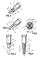
- the contact surfaces 9, 10 lie in contact planes K1, K2 which intersect at an angle of 90 °.
- the cross section of the plugged profile contacts forms a full circle, the contact surfaces 9 and 10 now visible as lines essentially extending from the center to the cross-sectional circumference.
- the transition surface formed in this way which is available for the current transfer, is thus relatively larger than in the pin-socket principle, in which at most linear contact can be achieved without the outer circumference of the hermaphrodite plug being enlarged thereby.
- the hermaphrodite plugs 3 and 4 are made in one piece from copper, and the surface can be silver-plated or provided with a silver alloy for an improved current transfer against environmental influences.
- a fastening section is provided in the hermaphrodite plug 3, 4, which can be penetrated by a transverse bore to fix the hermaphrodite plug in the housing 1 or 2.
- the embodiment is the hermaphrodite plug held in the housing 1 or 2 by a hollow screw 15, which also serves for the cable entry.
- a first variant of a spring sleeve 13 is shown in more detail in FIG. 7.
- the spring sleeve 13 generally has a C shape, with its two free ends 14 of the C shape resting on the non-contacting outer sides of the two profile contacts 7 and 8.
- the free ends 14 are adapted to the contour of the outer circumference of the plug section.
- the free ends 14 are connected to one another by a connecting section 15 which nestles against the facing contact surfaces 10 and 9 of the profile contacts 7 and 8, so that the connecting section has a total of three locations with relatively strong curvatures.
- the connecting section 15 also serves as a stop when two connectors are plugged together.
- FIG. 18 Another variant of the spring is shown in Fig. 18.
- the connecting section 15 'connecting the two free ends 14 of the C-shaped spring 13 is bulged radially outward, so that here too there is a change in curvature between the connecting section 15' and the two free ends 14.
- the profile contacts of the other connector can be pushed under the spring, so that the contact area available when plugged in can be enlarged.
- the banjo bolt 15 is first placed on the cable. Then the cable end is stripped, after which a hermaphrodite plug 3 with its crimp sleeve is pushed onto the stripped end of the cable 14. The crimp sleeve 5 is then squeezed together, after which the housing 1 is pushed over the hermaphrodite plug 3 and is non-positively connected to the hermaphrodite plug 3 by screwing in the hollow screw 15. The same happens with the cable 14 'and the hermaphrodite plug 4. The hermaphrodite plugs 3 and 4 must now be rotated 90 ° relative to one another and can then be plugged together, resulting in a contact cross section as shown in FIG. 6.
- the contact force between the contact surfaces 9 and 10 of the respective profile contacts 7, 8 and 7 ', 8' is applied essentially solely by the spring sleeve 13. This makes it possible to produce the contact surfaces completely flat in the manufacture of the hermaphrodite plug, so that when the connector is plugged in, a full-surface contact of the contact surfaces is achieved.
- the use of a spring sleeve made of a bimetallic strip also has the advantage that the contact force is increased when the connector set is subjected to a high current, which generally results in heating. This in turn has the consequence that the current transfer is improved and thus the contact heating decreases.
Landscapes
- Coupling Device And Connection With Printed Circuit (AREA)
- Connector Housings Or Holding Contact Members (AREA)
Applications Claiming Priority (2)
| Application Number | Priority Date | Filing Date | Title |
|---|---|---|---|
| DE8914923U DE8914923U1 (de) | 1989-12-19 | 1989-12-19 | Steckverbindersatz mit zwei langgestreckten Zwittersteckern |
| DE8914923U | 1989-12-19 |
Publications (2)
| Publication Number | Publication Date |
|---|---|
| EP0433802A1 true EP0433802A1 (fr) | 1991-06-26 |
| EP0433802B1 EP0433802B1 (fr) | 1994-09-28 |
Family
ID=6845625
Family Applications (1)
| Application Number | Title | Priority Date | Filing Date |
|---|---|---|---|
| EP90123573A Expired - Lifetime EP0433802B1 (fr) | 1989-12-19 | 1990-12-07 | Connecteur pour courant élevé avec deux fiches hermaphrodites |
Country Status (3)
| Country | Link |
|---|---|
| EP (1) | EP0433802B1 (fr) |
| BG (1) | BG60040B2 (fr) |
| DE (2) | DE8914923U1 (fr) |
Cited By (2)
| Publication number | Priority date | Publication date | Assignee | Title |
|---|---|---|---|---|
| WO2018024462A1 (fr) * | 2016-08-01 | 2018-02-08 | Phoenix Contact Gmbh & Co. Kg | Élément de contact électrique hermaphrodite |
| GB2580376A (en) * | 2019-01-07 | 2020-07-22 | Harwin Plc | Electrical Connector |
Families Citing this family (1)
| Publication number | Priority date | Publication date | Assignee | Title |
|---|---|---|---|---|
| DE102010008112A1 (de) * | 2010-02-15 | 2011-08-18 | Amphenol-Tuchel Electronics GmbH, 74080 | Hochstromkontaktelement |
Citations (1)
| Publication number | Priority date | Publication date | Assignee | Title |
|---|---|---|---|---|
| US2441921A (en) * | 1943-11-09 | 1948-05-18 | Albert & J M Anderson Mfg Co | Electrical connector |
-
1989
- 1989-12-19 DE DE8914923U patent/DE8914923U1/de not_active Expired - Lifetime
-
1990
- 1990-12-07 EP EP90123573A patent/EP0433802B1/fr not_active Expired - Lifetime
- 1990-12-07 DE DE59007336T patent/DE59007336D1/de not_active Expired - Fee Related
- 1990-12-18 BG BG093480A patent/BG60040B2/bg unknown
Patent Citations (1)
| Publication number | Priority date | Publication date | Assignee | Title |
|---|---|---|---|---|
| US2441921A (en) * | 1943-11-09 | 1948-05-18 | Albert & J M Anderson Mfg Co | Electrical connector |
Non-Patent Citations (1)
| Title |
|---|
| IBM TECHNICAL DISCLOSURE BULLETIN. vol. 17, no. 12, Mai 1975, NEW YORK US Seiten 3658 - 3659; A.C.Birnstill R.T.Evans: "POWER CONNECTOR" * |
Cited By (2)
| Publication number | Priority date | Publication date | Assignee | Title |
|---|---|---|---|---|
| WO2018024462A1 (fr) * | 2016-08-01 | 2018-02-08 | Phoenix Contact Gmbh & Co. Kg | Élément de contact électrique hermaphrodite |
| GB2580376A (en) * | 2019-01-07 | 2020-07-22 | Harwin Plc | Electrical Connector |
Also Published As
| Publication number | Publication date |
|---|---|
| DE8914923U1 (de) | 1991-04-18 |
| EP0433802B1 (fr) | 1994-09-28 |
| DE59007336D1 (de) | 1994-11-03 |
| BG60040B2 (bg) | 1993-07-30 |
Similar Documents
| Publication | Publication Date | Title |
|---|---|---|
| EP2442403B1 (fr) | Borne de connexion sans vis | |
| EP2255412B1 (fr) | Dispositif de connexion électrique | |
| DE69426133T2 (de) | Elektrische Kontaktstruktur mit geringer Einsteckkraft | |
| DE69300865T3 (de) | Elektrischer verbinder mit blech als steckkontaktmaterial. | |
| DE69602096T2 (de) | Abgeschirmtes kabelende für eine elektrische steckvorrichtung | |
| EP3782238B1 (fr) | Système de modules de connecteur enfichable blindés pour connecteurs enfichables industriels modulaires | |
| DE2413174A1 (de) | Elektrischer verbinder | |
| DE4111054C2 (fr) | ||
| EP3000153A1 (fr) | Cavalier enfichable comprenant des éléments en tôle superposés | |
| DE69221428T2 (de) | Elektrische Kontaktbuchse | |
| DE2939474C2 (de) | Elektrischer Steckverbinder | |
| DE3912189A1 (de) | Schutzleiterverbindung | |
| DE19809706B4 (de) | Quetschklemme | |
| DE7837478U1 (de) | AnschluBteU für elektrische Leitungen | |
| DE10347306A1 (de) | Schirmanbindung | |
| EP0968548B1 (fr) | Douille munie de zones de contact a configuration hyperboloidale | |
| EP0433802B1 (fr) | Connecteur pour courant élevé avec deux fiches hermaphrodites | |
| DE3906625C1 (de) | Elektrisches Steckkontaktteil | |
| DE3408006C2 (de) | Leiteranschluß, insbesondere für Hochstromklemmen | |
| EP0319633B1 (fr) | Connecteur cinch | |
| DE102005012441A1 (de) | Elektrischer Steckverbinder sowie Verfahren zur Herstellung eines elektrischen Steckverbinders | |
| EP1302720A2 (fr) | Douille de lampe et bloc optique comprenant douille de lampe et réflecteur | |
| DE19921132C1 (de) | Kabelstecker für elektrische Verbindungen | |
| DE102020133968A1 (de) | Elektrische anschlussanordnung mit vergrössertem kontaktbereich | |
| AT410614B (de) | Kabelstecker mit einem steckergehäuse und elektrischen kontaktelementen |
Legal Events
| Date | Code | Title | Description |
|---|---|---|---|
| PUAI | Public reference made under article 153(3) epc to a published international application that has entered the european phase |
Free format text: ORIGINAL CODE: 0009012 |
|
| 17P | Request for examination filed |
Effective date: 19910429 |
|
| AK | Designated contracting states |
Kind code of ref document: A1 Designated state(s): DE FR GB IT SE |
|
| 17Q | First examination report despatched |
Effective date: 19930507 |
|
| RAP1 | Party data changed (applicant data changed or rights of an application transferred) |
Owner name: SCHALTBAU AKTIENGESELLSCHAFT |
|
| GRAA | (expected) grant |
Free format text: ORIGINAL CODE: 0009210 |
|
| AK | Designated contracting states |
Kind code of ref document: B1 Designated state(s): DE FR GB IT SE |
|
| REF | Corresponds to: |
Ref document number: 59007336 Country of ref document: DE Date of ref document: 19941103 |
|
| ET | Fr: translation filed | ||
| GBT | Gb: translation of ep patent filed (gb section 77(6)(a)/1977) |
Effective date: 19941010 |
|
| ITF | It: translation for a ep patent filed | ||
| EAL | Se: european patent in force in sweden |
Ref document number: 90123573.9 |
|
| PLBE | No opposition filed within time limit |
Free format text: ORIGINAL CODE: 0009261 |
|
| STAA | Information on the status of an ep patent application or granted ep patent |
Free format text: STATUS: NO OPPOSITION FILED WITHIN TIME LIMIT |
|
| 26N | No opposition filed | ||
| PGFP | Annual fee paid to national office [announced via postgrant information from national office to epo] |
Ref country code: GB Payment date: 19961118 Year of fee payment: 7 |
|
| PGFP | Annual fee paid to national office [announced via postgrant information from national office to epo] |
Ref country code: FR Payment date: 19961216 Year of fee payment: 7 |
|
| PGFP | Annual fee paid to national office [announced via postgrant information from national office to epo] |
Ref country code: SE Payment date: 19961220 Year of fee payment: 7 |
|
| PGFP | Annual fee paid to national office [announced via postgrant information from national office to epo] |
Ref country code: DE Payment date: 19970130 Year of fee payment: 7 |
|
| PG25 | Lapsed in a contracting state [announced via postgrant information from national office to epo] |
Ref country code: GB Free format text: LAPSE BECAUSE OF NON-PAYMENT OF DUE FEES Effective date: 19971207 |
|
| PG25 | Lapsed in a contracting state [announced via postgrant information from national office to epo] |
Ref country code: SE Free format text: LAPSE BECAUSE OF NON-PAYMENT OF DUE FEES Effective date: 19971208 |
|
| PG25 | Lapsed in a contracting state [announced via postgrant information from national office to epo] |
Ref country code: FR Free format text: THE PATENT HAS BEEN ANNULLED BY A DECISION OF A NATIONAL AUTHORITY Effective date: 19971231 |
|
| GBPC | Gb: european patent ceased through non-payment of renewal fee |
Effective date: 19971207 |
|
| PG25 | Lapsed in a contracting state [announced via postgrant information from national office to epo] |
Ref country code: DE Free format text: LAPSE BECAUSE OF NON-PAYMENT OF DUE FEES Effective date: 19980901 |
|
| EUG | Se: european patent has lapsed |
Ref document number: 90123573.9 |
|
| REG | Reference to a national code |
Ref country code: FR Ref legal event code: ST |
|
| PG25 | Lapsed in a contracting state [announced via postgrant information from national office to epo] |
Ref country code: IT Free format text: LAPSE BECAUSE OF NON-PAYMENT OF DUE FEES;WARNING: LAPSES OF ITALIAN PATENTS WITH EFFECTIVE DATE BEFORE 2007 MAY HAVE OCCURRED AT ANY TIME BEFORE 2007. THE CORRECT EFFECTIVE DATE MAY BE DIFFERENT FROM THE ONE RECORDED. Effective date: 20051207 |