EP0433843A2 - Arbre creux et procédé pour sa fabrication - Google Patents
Arbre creux et procédé pour sa fabrication Download PDFInfo
- Publication number
- EP0433843A2 EP0433843A2 EP90123766A EP90123766A EP0433843A2 EP 0433843 A2 EP0433843 A2 EP 0433843A2 EP 90123766 A EP90123766 A EP 90123766A EP 90123766 A EP90123766 A EP 90123766A EP 0433843 A2 EP0433843 A2 EP 0433843A2
- Authority
- EP
- European Patent Office
- Prior art keywords
- shaft
- decorative
- synthetic resin
- carrier
- fabric
- Prior art date
- Legal status (The legal status is an assumption and is not a legal conclusion. Google has not performed a legal analysis and makes no representation as to the accuracy of the status listed.)
- Withdrawn
Links
Images


Classifications
-
- B—PERFORMING OPERATIONS; TRANSPORTING
- B29—WORKING OF PLASTICS; WORKING OF SUBSTANCES IN A PLASTIC STATE IN GENERAL
- B29C—SHAPING OR JOINING OF PLASTICS; SHAPING OF MATERIAL IN A PLASTIC STATE, NOT OTHERWISE PROVIDED FOR; AFTER-TREATMENT OF THE SHAPED PRODUCTS, e.g. REPAIRING
- B29C53/00—Shaping by bending, folding, twisting, straightening or flattening; Apparatus therefor
- B29C53/56—Winding and joining, e.g. winding spirally
- B29C53/562—Winding and joining, e.g. winding spirally spirally
-
- A—HUMAN NECESSITIES
- A01—AGRICULTURE; FORESTRY; ANIMAL HUSBANDRY; HUNTING; TRAPPING; FISHING
- A01K—ANIMAL HUSBANDRY; AVICULTURE; APICULTURE; PISCICULTURE; FISHING; REARING OR BREEDING ANIMALS, NOT OTHERWISE PROVIDED FOR; NEW BREEDS OF ANIMALS
- A01K87/00—Fishing rods
-
- B—PERFORMING OPERATIONS; TRANSPORTING
- B29—WORKING OF PLASTICS; WORKING OF SUBSTANCES IN A PLASTIC STATE IN GENERAL
- B29L—INDEXING SCHEME ASSOCIATED WITH SUBCLASS B29C, RELATING TO PARTICULAR ARTICLES
- B29L2031/00—Other particular articles
- B29L2031/70—Agricultural usage or equipment
- B29L2031/7002—Agricultural usage or equipment for fishing
Definitions
- the invention initially relates to a hollow cylindrical or hollow conical shaft in the form of a rod body for or on fishing rods, or as a shaft for or on ski poles, golf clubs and surf poles, the shaft consisting of a multi-layer shaft material made of resin-impregnated material and a decoration provided on the outside (Preamble of claim 1).
- a rod body means both the entire fishing rod and, in the case of fishing rods composed of several parts, the individual parts thereof.
- the present invention thus relates both to fishing rods which consist of only one rod body and to fishing rods which are composed of a plurality of rod bodies which are plugged into one another or telescopically or in some other way connected.
- the material of this rod body consists of a stronger fabric, e.g. B.
- This film is crystal clear, so that the viewer not only sees the representations on the uppermost winding layer, but also on the winding layers of the film underneath.
- This overlapping of the representations of the wrapping layers of the film means that only a more or less diffuse decor can be achieved.
- Shafts according to the preamble of claim 1 are connected in the case of golf clubs with striking part and handle, in the case of ski poles with the pole tip, snow plate and handle, and in the case of surf masts with the necessary fastening parts for the sail and the assembly of the mast on Provide surfboard.
- the material of these shafts consists of a roll of a stronger fabric, for example a corresponding glass fiber or carbon fiber fabric, which is impregnated with synthetic resin (so-called prepreg).
- the winding impregnated with synthetic resin is heated, whereby the plastic material (eg polyester, phenol or epoxy resin impregnation) hardens as a result of the heating.
- the winding itself has previously been wrapped around a mandrel which is pulled out after hardening.
- the winding material and the plastic material penetrating this form a very strong, stable shaft after heating and curing.
- Such stems are used on their Provide the outer surface with a printed decor, which decor can also consist of text references and / or the trademark of the manufacturer and the like.
- the above printing is usually done by screen printing.
- the object of the invention is first of all to design a shaft in accordance with the preamble of claim 1 specified at the outset in such a way that it can have a decor on its entire outer surface with relatively little production effort, this decor should be clearly and clearly visible.
- the cut of the decor carrier results in a rectangle or a trapezoid. Claim 2 or 3.
- the features of claim 6 include either straight-line overlaps or, if a corresponding, so-called optical resolution is desired, jagged, wavy or similar edges of the overlap. In the latter case, the overlapping edges are not as visible as in the first case.
- this glass fiber layer is crystal clear, i.e. allows an unobstructed view of the decor.
- the invention further relates to a method for producing a hollow, cylindrical or conical shaft in the form of a rod body for or on fishing rods, or as a shaft for ski poles, golf clubs and surf masts, initially around a core of a single layer impregnated with synthetic resin or the like, made of one fabric existing shaft material is wrapped (prepreg), then a holder, preferably in spiral form a cellophane tape, is applied around the shaft material, then a heat treatment is carried out which melts the resin impregnation of the prepreg and then the holder and the core are removed (preamble of claim 9) .
- the rod bodies already described in relation to the prior art were provided with bands of unidirectional carbon fiber band which were wound in a spiral form on the rod body material.
- These tapes were wrapped with the holder, e.g. B. surrounded cellophane tapes. Thereafter, the entire rod body, including tapes and holder, was heated, whereupon the impregnation of synthetic resin or the like of the z. B. from two to seven winding layers of rod body material became liquid and - as far as possible - also soaked these tapes.
- the holder, z. B. said cellophane coating removed, and the core pulled out.
- the synthetic resin impregnation liquefied, the cellophane tapes had formed small gradations on the outer surface of the rod body material or the tapes, which were removed by grinding.
- the method features according to claim 10 deal with the attachment of a glass fiber layer and its impregnation during the heating process by the liquefied plastic material of the so-called prepreg.
- the glass fiber layer soaked is crystal clear (see above). It is of advantage in terms of manufacturing technology that their impregnation and that of the decor carrier are carried out in one operation by the liquefied plastic material of the prepreg.
- each rod body only has to be wrapped once around the shaft material with such a decorative support and possibly a glass fiber layer.
- an image, writing or the like extending over the entire length of the shaft can thus be provided on the decor carrier.
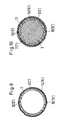
- a conical hollow shaft 1 or a cylindrical hollow shaft 1 ' is formed according to FIG. 8 or 10 so that a multi-layer winding 3 is wound from a material soaked with synthetic resin around a correspondingly shaped core 2.
- the aforementioned material can be a suitably strong textile or plastic fabric or a glass fiber or carbon fiber fabric. The cut of this material is trapezoidal for the production of a conical shaft according to number 3 in FIG. 2 (or rectangular for the production of a cylindrical shaft according to number 3 '(FIG. 5)).
- the length l1 or l2 of the narrow edges of the trapezoid are chosen so that the desired number of winding layers can be applied.
- the difference l1, l2 and thus the inclination of one long side 4 to the other long side 5 are adapted to the taper of the shaft 1 such that after wrapping the core 2, the longitudinal edges 4, 5 run parallel to the central longitudinal axis 6 of the shaft.
- Only the lengths of the narrow sides 8, 9 are selected so that after only one winding of the shaft material formed by the winding 3, the long sides 10, 11 either abut one another or according to a preferred one Embodiment of the invention overlap somewhat according to number 12 in FIGS. 7, 8.
- the length of the overlap 12 can be 1 mm.
- the decorative support 7 consists of a nonwoven fabric or a fabric, for example a tulle, which is relatively thin and is capable of absorbing the liquefied synthetic resin of the fabric 3 during the heating to be explained in more detail below.
- a holder which is only shown schematically in FIG. 8, is then applied in the form of a spirally wound celluloid band 13, the individual windings of this spiral overlapping somewhat.
- the shaft with core 2 and holder 13 is then heated to such an extent that the synthetic resin impregnation of the windings (prepreg) 3 or 3 'becomes liquid and also soak the nonwoven fabric or the fabric of the decor carrier 7 or 7'.
- the thinness of the fabric or nonwoven and the amount of synthetic resin impregnation of the windings 3, 3 'which is released during the above heating process and which is liquid during the heating are matched to one another in such a way that the synthetic resin excess from the prepreg is sufficient to completely soak the nonwoven fabric or the fabric.
- nonwoven fabric has proven particularly suitable proven because the threads forming the nonwoven are disordered, ie not straight, and the nonwoven thus has a particularly strong absorbency for the liquid synthetic resin.
- a non-woven fabric with a thickness of 0.3 mm is used. This information is given only as an example, ie the invention is not limited to this number.
- the total length of the parts 3, 7 or 3 ', 7' is equal to the total length of the associated shaft 1 or 1 '.
- the winding direction of the parts 3, 7 or 3 ', 7' is in the circumferential direction U or U ', preferably with the formation of the overlap 12 or 12' already explained, which is shown in FIGS. 3 and 6 by a dashed line Line is indicated.
- the overlapping long sides of the decorative supports can either be straight according to numbers 10, 11 in FIG. 3 or jagged according to numbers 10 ', 11' in FIG. 6, or they may also be corrugated. In the latter case, there is better optical resolution, i.e. the overlapped edges cannot be seen as clearly as in the exemplary embodiment in FIG. 3.
- the end product is a shaft, in which the decorative support and the shaft material are absolutely firmly connected to each other by the resin impregnation, the shaft material and decorative carrier being pressed together during heating due to the use of the holder in the form of a cellophane tape.
- the shaft shown in FIG. 7 is in one piece in cross-section, the decor of the carrier being clearly recognizable from the outside and the desired one Effect there.
- the decor carrier surrounds the entire outer surface of the shaft with the decor.
- FIGS. 9 and 10 show a further embodiment of the invention with a glass fiber layer 14 or 14 ', which surrounds the respective decorative support 7 or 7' and is also impregnated with the liquid synthetic resin of the prepreg in the heating process explained.
- this glass fiber layer is provided, care must be taken to ensure that the liquid quantity of synthetic resin released is sufficient to impregnate the glass fiber layer in addition to the decorative support.
- a glass fiber layer so saturated is crystal clear. The decor is perfectly visible through it.
- the glass fiber layer 14 or 14 ' protects the decor carrier from dirt and / or damage.
- the procedure is preferably such that the glass fiber layer 14 or 14 'has the same cut as the associated decorative support 7 or 7' (see FIGS. 3 and 6).
- the corresponding glass fiber layer is wound on the decor carrier, it preferably also having a corresponding overlap 15 or 15' on its longitudinal edges. Then the holder 13 is applied and the method explained above is carried out.
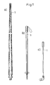
- the above exemplary embodiments relate both to the production of rod bodies on or for fishing rods, these rod bodies being able to have either a conical outer shape according to FIG. 1 or a cylindrical outer shape according to FIG. 4.
- Shafts for surf masts, ski poles or golf clubs can also be produced in accordance with the above exemplary embodiments, which shafts are then provided or connected with the associated parts of the surf mast or the surfboard, the ski pole and the golf club, which can be done, for example, by gluing.
- Fig. 11a using the shaft 1 of a surf pole Fig. 11b using the shaft 1 of a ski pole
- Fig. 11c using the shaft 1 of a golf club, such as in each case a socket for attachment to the surfboard, or ski tip and handle , or golf club and handle are attached.
Landscapes
- Life Sciences & Earth Sciences (AREA)
- Environmental Sciences (AREA)
- Engineering & Computer Science (AREA)
- Mechanical Engineering (AREA)
- Marine Sciences & Fisheries (AREA)
- Animal Husbandry (AREA)
- Biodiversity & Conservation Biology (AREA)
- Golf Clubs (AREA)
- Laminated Bodies (AREA)
- Fishing Rods (AREA)
Applications Claiming Priority (4)
| Application Number | Priority Date | Filing Date | Title |
|---|---|---|---|
| DE3941954 | 1989-12-20 | ||
| DE19893941954 DE3941954C1 (en) | 1989-12-20 | 1989-12-20 | Hollow cylindrical rod member for fishing rod - comprises multilayered material soaked in synthetic resin |
| DE4015513 | 1990-05-15 | ||
| DE19904015513 DE4015513C2 (de) | 1989-12-20 | 1990-05-15 | Hohler Schaft für oder an Skistöcken, Golfschlägern und Surfmasten sowie Verfahren zu seiner Herstellung |
Publications (2)
| Publication Number | Publication Date |
|---|---|
| EP0433843A2 true EP0433843A2 (fr) | 1991-06-26 |
| EP0433843A3 EP0433843A3 (en) | 1992-01-22 |
Family
ID=25888181
Family Applications (1)
| Application Number | Title | Priority Date | Filing Date |
|---|---|---|---|
| EP19900123766 Withdrawn EP0433843A3 (en) | 1989-12-20 | 1990-12-11 | Hollow shaft and method for its manufacture |
Country Status (2)
| Country | Link |
|---|---|
| EP (1) | EP0433843A3 (fr) |
| DE (1) | DE4015513C2 (fr) |
Cited By (4)
| Publication number | Priority date | Publication date | Assignee | Title |
|---|---|---|---|---|
| US5964056A (en) * | 1997-04-24 | 1999-10-12 | Berkley Inc. | Graphite fiber fishing rod blank incorporating a non-woven non-unidirectional material |
| GB2343353A (en) * | 1998-11-03 | 2000-05-10 | You Chin San | Fishing rod. |
| US8128994B1 (en) | 2008-09-30 | 2012-03-06 | Taylor Made Golf Company, Inc. | Method of applying decorative layers to a steel shaft |
| WO2016042506A1 (fr) * | 2014-09-19 | 2016-03-24 | Faps S.R.L. | Procédé pour la fabrication de cannes à pêche et canne à pêche fabriquée à l'aide de ce procédé |
Families Citing this family (1)
| Publication number | Priority date | Publication date | Assignee | Title |
|---|---|---|---|---|
| DE4236433C2 (de) * | 1992-10-28 | 1996-09-12 | Klaus Lenhart | Ski- oder Wanderstock |
Family Cites Families (11)
| Publication number | Priority date | Publication date | Assignee | Title |
|---|---|---|---|---|
| US2768921A (en) * | 1954-05-20 | 1956-10-30 | Robert F Pigg | Method of molding tapered rods |
| US2809144A (en) * | 1955-01-27 | 1957-10-08 | Narmco Sporting Goods Company | Method of making a composite golf shaft for a golf club |
| DE1901052A1 (de) * | 1966-04-15 | 1970-08-13 | J Stroemer Schomers Fa | Verfahren zur Herstellung von mit Schriftzuegen oder Abbildungen versehenen transparenten Platten |
| FR1590084A (fr) * | 1968-01-24 | 1970-04-13 | ||
| CA963372A (en) * | 1970-06-12 | 1975-02-25 | Westvaco Corporation | Laminated materials and manufacture thereof |
| FR2230491A1 (en) * | 1973-05-24 | 1974-12-20 | Basso Robert | Tubular structures with offset fibre reinforcement - made by rolling panes cut oblique to a stock reinforced prepregnated |
| JPS5398289A (en) * | 1977-02-03 | 1978-08-28 | Dainippon Ink & Chemicals | Method for producing angling rods |
| US4304620A (en) * | 1979-11-05 | 1981-12-08 | Abu Garcia, Inc. | Method of applying decorative windings to fishing rods |
| DE3129438A1 (de) * | 1981-07-25 | 1983-09-22 | Strasmann & Zimmermann, 5630 Remscheid | Verfahren zum anbringen von beschriftungen od.dgl. an aus kunststoff bestehenden teilen |
| US4555113A (en) * | 1983-04-06 | 1985-11-26 | Komei Shibata | Shaft and a method for producing the same |
| US4757997A (en) * | 1986-06-06 | 1988-07-19 | Fiber-Speed International, Inc. | Golf club shaft and method of manufacture |
-
1990
- 1990-05-15 DE DE19904015513 patent/DE4015513C2/de not_active Expired - Fee Related
- 1990-12-11 EP EP19900123766 patent/EP0433843A3/de not_active Withdrawn
Cited By (6)
| Publication number | Priority date | Publication date | Assignee | Title |
|---|---|---|---|---|
| US5964056A (en) * | 1997-04-24 | 1999-10-12 | Berkley Inc. | Graphite fiber fishing rod blank incorporating a non-woven non-unidirectional material |
| GB2343353A (en) * | 1998-11-03 | 2000-05-10 | You Chin San | Fishing rod. |
| GB2343353B (en) * | 1998-11-03 | 2002-12-31 | Chin-San You | Fishing rod |
| US8128994B1 (en) | 2008-09-30 | 2012-03-06 | Taylor Made Golf Company, Inc. | Method of applying decorative layers to a steel shaft |
| US8556744B1 (en) | 2008-09-30 | 2013-10-15 | Taylor Made Golf Company, Inc. | Method of applying decorative layers to a steel shaft |
| WO2016042506A1 (fr) * | 2014-09-19 | 2016-03-24 | Faps S.R.L. | Procédé pour la fabrication de cannes à pêche et canne à pêche fabriquée à l'aide de ce procédé |
Also Published As
| Publication number | Publication date |
|---|---|
| DE4015513C2 (de) | 1994-03-31 |
| DE4015513A1 (de) | 1991-11-21 |
| EP0433843A3 (en) | 1992-01-22 |
Similar Documents
| Publication | Publication Date | Title |
|---|---|---|
| DE4335221C1 (de) | Rotorblatt für Windkraftanlagen | |
| EP3245265B1 (fr) | Bande adhésive, notamment une bande enveloppante | |
| DE1961491C3 (de) | Verfahren und Vorrichtung zur Herstellung von Tennisschlägerrahmen | |
| DE69207650T2 (de) | Rute und Methode zur Herstellung derselben | |
| DE1775881C3 (de) | Verfahren zum Herstellen einer Drahtwendel für einen flexiblen Schlauch | |
| DE3639136A1 (de) | Flansch aus faserverstaerktem thermohaertendem kunstharz und verfahren zu seiner herstellung | |
| EP1108830A1 (fr) | Coffrage tubulaire et méthode de coffrage et de décoffrage d'éléments de construction | |
| DE2348011C3 (de) | Verfahren zum Herstellen eines rohrförmigen Körpers aus übereinanderliegenden Schichten aus mit warmhärtendem Kunststoff imprägnierten Kohlenstoff-Fasern | |
| DE3243357A1 (de) | Langgestreckte bauelemente | |
| EP0433843A2 (fr) | Arbre creux et procédé pour sa fabrication | |
| DE69906601T2 (de) | Verfahren und Vorrichtung zur simultanen Aufwicklung von mehreren vorimprägnierten Fasersträngen auf einen Kern und so hergestellte Verbundwerkstoffstrukturen | |
| DE19736575A1 (de) | Walze | |
| DE3941954C1 (en) | Hollow cylindrical rod member for fishing rod - comprises multilayered material soaked in synthetic resin | |
| DE69932882T2 (de) | Griff sowie Verfahren zu seiner Herstellung | |
| DE3780225T2 (de) | Verfahren zur herstellung von stoffmustern. | |
| DE3245061A1 (de) | Angelrute mit verbesserten wurfeigenschaften und kern zur herstellung derselben | |
| DE3841228C2 (fr) | ||
| DE69718287T2 (de) | Mähfaden für busch- und kantentrimmer | |
| DE102016007464A1 (de) | Verstärkungsstreifen für ein rohrförmiges bauteil aus verbundmaterial | |
| EP0161265B1 (fr) | Procede et appareil pour la fabrication d'une bande helicoidale de jupe et d'un isolateurde ligne aerienne | |
| DE2830848A1 (de) | Verfahren und vorrichtung fuer die herstellung eines glasfaserbuendels zur verwendung in optischen kommunikationsanlagen | |
| DE1153607B (de) | Garntraegerhuelse und Verfahren zu deren Herstellung | |
| DE19511303C2 (de) | Hilfmittel zum Schutz der Kopfhaut bei der Formung von Dauerwellen | |
| DE3932185C1 (en) | Paint roller applying paint to printing wheels etc. - has colour storage unit surrounding core consisting of open pored pref. polyurethane foam with non-porous outer mantle around storage unit | |
| DE19737979C2 (de) | Köderelement, Verfahren zu dessen Herstellung sowie Vorrichtung zur Durchführung des Verfahrens |
Legal Events
| Date | Code | Title | Description |
|---|---|---|---|
| PUAI | Public reference made under article 153(3) epc to a published international application that has entered the european phase |
Free format text: ORIGINAL CODE: 0009012 |
|
| AK | Designated contracting states |
Kind code of ref document: A2 Designated state(s): BE DE FR GB IT NL |
|
| PUAL | Search report despatched |
Free format text: ORIGINAL CODE: 0009013 |
|
| AK | Designated contracting states |
Kind code of ref document: A3 Designated state(s): BE DE FR GB IT NL |
|
| 17P | Request for examination filed |
Effective date: 19920711 |
|
| 17Q | First examination report despatched |
Effective date: 19930707 |
|
| STAA | Information on the status of an ep patent application or granted ep patent |
Free format text: STATUS: THE APPLICATION IS DEEMED TO BE WITHDRAWN |
|
| 18D | Application deemed to be withdrawn |
Effective date: 19941220 |