EP0433916A1 - Lampe fluorescente avec lumière de couleur bleue émettant du phosphore non déteriorant - Google Patents
Lampe fluorescente avec lumière de couleur bleue émettant du phosphore non déteriorant Download PDFInfo
- Publication number
- EP0433916A1 EP0433916A1 EP90124259A EP90124259A EP0433916A1 EP 0433916 A1 EP0433916 A1 EP 0433916A1 EP 90124259 A EP90124259 A EP 90124259A EP 90124259 A EP90124259 A EP 90124259A EP 0433916 A1 EP0433916 A1 EP 0433916A1
- Authority
- EP
- European Patent Office
- Prior art keywords
- fluorescent lamp
- envelope
- lamp according
- phosphor
- light
- Prior art date
- Legal status (The legal status is an assumption and is not a legal conclusion. Google has not performed a legal analysis and makes no representation as to the accuracy of the status listed.)
- Withdrawn
Links
Images




Classifications
-
- H—ELECTRICITY
- H01—ELECTRIC ELEMENTS
- H01J—ELECTRIC DISCHARGE TUBES OR DISCHARGE LAMPS
- H01J61/00—Gas-discharge or vapour-discharge lamps
- H01J61/02—Details
- H01J61/38—Devices for influencing the colour or wavelength of the light
- H01J61/42—Devices for influencing the colour or wavelength of the light by transforming the wavelength of the light by luminescence
-
- C—CHEMISTRY; METALLURGY
- C09—DYES; PAINTS; POLISHES; NATURAL RESINS; ADHESIVES; COMPOSITIONS NOT OTHERWISE PROVIDED FOR; APPLICATIONS OF MATERIALS NOT OTHERWISE PROVIDED FOR
- C09K—MATERIALS FOR MISCELLANEOUS APPLICATIONS, NOT PROVIDED FOR ELSEWHERE
- C09K11/00—Luminescent materials, e.g. electroluminescent or chemiluminescent
- C09K11/08—Luminescent materials, e.g. electroluminescent or chemiluminescent containing inorganic luminescent materials
- C09K11/67—Luminescent materials, e.g. electroluminescent or chemiluminescent containing inorganic luminescent materials containing refractory metals
- C09K11/671—Chalcogenides
- C09K11/673—Chalcogenides with alkaline earth metals
-
- C—CHEMISTRY; METALLURGY
- C09—DYES; PAINTS; POLISHES; NATURAL RESINS; ADHESIVES; COMPOSITIONS NOT OTHERWISE PROVIDED FOR; APPLICATIONS OF MATERIALS NOT OTHERWISE PROVIDED FOR
- C09K—MATERIALS FOR MISCELLANEOUS APPLICATIONS, NOT PROVIDED FOR ELSEWHERE
- C09K11/00—Luminescent materials, e.g. electroluminescent or chemiluminescent
- C09K11/08—Luminescent materials, e.g. electroluminescent or chemiluminescent containing inorganic luminescent materials
- C09K11/70—Luminescent materials, e.g. electroluminescent or chemiluminescent containing inorganic luminescent materials containing phosphorus
- C09K11/701—Chalcogenides
-
- H—ELECTRICITY
- H01—ELECTRIC ELEMENTS
- H01J—ELECTRIC DISCHARGE TUBES OR DISCHARGE LAMPS
- H01J61/00—Gas-discharge or vapour-discharge lamps
- H01J61/02—Details
- H01J61/38—Devices for influencing the colour or wavelength of the light
- H01J61/42—Devices for influencing the colour or wavelength of the light by transforming the wavelength of the light by luminescence
- H01J61/44—Devices characterised by the luminescent material
Definitions
- the present invention relates to a fluorescent lamp in which xenon or a rare gas containing mainly xenon is sealed in a bulb having electrodes, and phosphor is excited by the discharge of the xenon to radiate light.
- a light emitting tube-shaped bulb is composed, for example, of an extremely thin hollow glass tube having an inner diameter of approx. 2 - 3 mm.
- This bulb is used as a display needle of an instrument.
- One end of the discharge lamp is attached to the rotational shaft of a meter. When this rotational shaft is rotated, the discharge lamp is integrally moved through an arc. Thus, the discharge lamp performs the function of the display needle.
- the discharge lamp When the discharge lamp is ignited, the lamp has such advantages that the lamp itself emits a light and also illuminates the display scale so that special illumination is not required.
- the xenon discharge lamp used as the display needle of an instrument as described above has an inner electrode provided at one end of a tube-shaped bulb formed with a slender discharge space, a strip-like outer electrode provided along its axial direction on the outer surface of the bulb, and a phosphor film made of phosphors emitting three primary colors of light (hereinafter referred to as three primary color phosphors) on the inner surface of the discharge space.
- a cold cathode having an excellent lifetime characteristic is employed as the inner electrode, and xenon (Xe) or a mixture gas of mainly xenon and another gas such as neon, krypton, or argon, etc. is sealed in the discharge space.
- xenon (Xe) or a mixture gas of mainly xenon and another gas such as neon, krypton, or argon, etc.
- a high frequency voltage is applied between the inner electrode and the outer electrode to generate a discharge of rare gas, containing mainly xenon, in the discharge space.
- a shielding film made of synthetic resin is formed on the outer surface of the bulb and a slender light transmitting strip extending axially along the bulb is formed by removing a corresponding portion from the shielding film, and light is emitted only from the light transmitting strip. Therefore, a discharge lamp of this type is formed as an aperture type lamp. Thus, a light emitting unit as a display needle is formed in an extremely slim needle shape.
- the sealed discharge lamp containing xenon radiates ultraviolet rays within a spectrum of a short wavelength, by means of the discharge between the inner and outer electrodes, the short wavelength light ray excites the phosphor, and the phosphor radiates visible light.
- Red is formed of Y2O3:Eu
- green is formed of (La,Ce,Tb)2O3, 0.2SiO2, 0.9P2O5
- blue is formed of (Ba, Mg) 0.8Al2O3:Eu.
- blue color of light refers to radiations exhibiting blue emission substantially located in the wavelength range of from 430 nm to 485 nm.
- green color of light is in the wavelength range of from 515 nm to 570 nm
- red color of light is in the wavelength range of from 588 nm to 630 nm.
- a fluorescent lamp comprising:
- Fig. 1 is an exploded perspective view of a cold cathode fluorescent lamp and lamp holder according to a first embodiment of the present invention
- Fig. 2 is a plan view of Fig. 1;
- Fig. 3 is a sectional view taken along the line III-III of Fig. 2;
- Fig. 4 is a sectional view taken along the line IV-IV of Fig. 2;
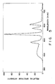
- Fig. 5 is a spectral distribution characteristic diagram
- Fig. 6 is a characteristic diagram showing the transition of chromaticity in the first and second embodiments
- Fig. 7 is an exploded perspective view of a cold cathode fluorescent lamp and lamp holder according to a second embodiment of the present invention.
- Fig. 8 is a plan view of the cold cathode fluorescent lamp shown in Fig. 7;
- Fig. 9 is a side view of the cold cathode fluorescent lamp shown in Fig. 7;
- Fig. 10 is a bottom view of the cold cathode fluorescent lamp shown in Fig. 7;
- Fig. 11 is a view of the outer electrode of the cold cathode fluorescent lamp shown in Fig. 7;
- Fig. 12 is a sectional view taken along the line VI-VI of Fig. 7;
- Fig. 13 is a characteristic diagram showing luminance distribution
- Fig. 14 is a sectional view showing one end of a cold cathode fluorescent lamp according to a third embodiment of the present invention.
- Fig. 15 is a characteristic diagram showing luminance maintainability
- Figs. 16, 17, 18 and 19 are views showing modified embodiments of a cold cathode fluorescent lamp.
- a xenon cold cathode fluorescent lamp 1 used as a display needle comprises a hollow rod-shaped glass bulb 2 formed with a slender discharge space 30 (shown in Fig. 3) therein.
- the glass bulb 2 has, for example, an outer diameter of 2.5 mm, a total length of approx. 60 mm, and is formed in a needle shape.
- An inner electrode (cold cathode) 3 is sealed in one end portion of the bulb 2, and the cold cathode 3 is connected to a lead wire 4 hermetically passed through the sealing end of the bulb 2.
- a phosphor film 5 is formed on the inner surface around the discharge space 30 of the bulb 3.
- the phosphor film 5 of this embodiment is formed of three primary color phosphors.
- Y2O3:Eu is employed similarly to the prior art as a red phosphor
- (La, Ce, Tb)2O3, 0.2SiO2, 0.9P2O5 is employed similarly to the prior art as a green phosphor.
- CaWO4 is employed as a blue phosphor.
- These phosphors of the three wavelengths are suitably adjusted and mixed.
- Xenon gas 40 (Fig. 3) is sealed at between 5 - 90 Torr, or preferably approx. 50 Torr, in the bulb 2.
- An outer electrode 6 having a strip shape is provided, as shown in Fig. 2, along the axial direction of the bulb 2 on the outer surface thereof.
- the outer electrode 6 is composed by coating, in a strip shape, the corresponding portion of the bulb 2 in a predetermined length from the end portion of the bulb 2 with paste such as carbon phenol or silver epoxy, baking it, and forming it in a film shape.
- a first receptacle terminal 10 is attached to the outer surface of the sealed end portion of the inner electrode 3 of the bulb 2.
- the first receptacle terminal 10 is formed, in a cap shape, of a conductive metal plate made of phosphorus bronze, etc., and covers the end portion of the bulb 2.
- the first receptacle terminal 10 is pushed into contact with the lead wire 4, hermetically passed through the end portion of the bulb 2, so as to be connected thereto.
- the following is a method of attaching the end portion of the inner electrode 3 to the first receptacle terminal 10.
- a hole can be opened in the first receptacle terminal 10 to be soldered later, or the end portion is coated with paste, covered with the first receptacle terminal 10, and then baked, or the end portion is coated with paste, baked and then covered with the first receptacle terminal 10.
- a second receptacle terminal 11 is provided at a position isolated axially with respect to the first receptacle terminal 10 on the outer surface of the bulb 2.
- the second receptacle terminal 11 is formed by bending a conductive metal piece made of phosphorus bronze in a ring shape around the bulb 2.
- the second receptacle terminal 11 is attached by elastic force to the bulb 2, and connected to the outer electrode 6, made of paste and formed on the outer surface of the bulb 2.
- the second receptacle terminal 11 surrounds the bulb 2 except for the slit portion 8 of the shielding film 7 to be described later.
- the shielding film 7 formed on the outer surface of the bulb 2 contains components of carbon, epoxy resin and adhesive.
- the shielding film 7 is formed to cover the outer electrode 6 on the surface of the bulb 2, and the light transmitting slit portion 8 not covered by the shielding film 7 extends axially along the surface opposed to the surface formed with the outer electrode 6.
- the outer electrode 6 is formed, as shown in the sectional view of Fig. 3, on one portion of the outer surface of the bulb 2, and the light transmitting slit portion 8 is not covered by the shielding film 7 and is formed on the surface of the fluorescent lamp 1 opposite (180 degrees from) the outer electrode 6. Accordingly, the light in the bulb 2 is externally radiated only through the light transmitting slit portion 8.
- the fluorescent lamp 1 is formed as an aperture type.
- the shielding film 7 is formed on the entire surface of the bulb 2 except the first and second receptacle terminals 10 and 11, in addition to the light transmitting slit portion 8, and the first and second receptacle terminals 10 and 11 are directly exposed on the outer surface of the lamp 1.
- the xenon discharge lamp 1 constructed as described above is attached to a lamp holder 20.
- the lamp holder 20 is formed, in a square U-shaped section, of an electrically insulating material, and first and second power supply terminal tongue pieces 21 and 22 are so fixed as to be isolated along the axial direction.
- These power supply terminal tongue pieces 21 and 22 are formed by bending conductive leaf springs made of phosphorus bronze, etc. in a U shape, to hold the bulb 2 by means of holding pieces 23a and 23b opposed to each other as shown by broken lines in Fig. 3.
- the lamp holder 20 is fixed to the display rotational shaft 25 of an instrument. When the rotational shaft 25 is rotated, the lamp holder 20 is correspondingly pivoted.
- the rotational shaft 25 of this embodiment is composed of a hollow shaft, not shown.
- Two coated cords (not shown) are inserted into the hollow display shaft 25, the ends of the coated cords are respectively connected to the first and second power supply terminal tongue pieces 21 and 22, and connected at their other ends to a high frequency power source.
- the lamp 1 is attached at the end portion thereof so as to connect the inner electrode 3 to the lamp holder 20.
- the first and second receptacle terminals 10 and 11 formed on the outer surface of the bulb 2 in corresponding positions to the first and second power supply terminal tongue pieces 21 and 22 of the lamp holder 20.
- the holding pieces 23a and 23b of the first and second power supply terminal tongue pieces 21 and 22 respectively hold the portions of the first and second receptacle terminals 10 and 11 so as to mechanically hold the bulb 2. Accordingly, the discharge lamp 1 is fixed to the lamp holder 20.
- the inner and outer electrodes 3 and 6 are connected to the high frequency power source.
- the cold cathode discharge lamp 1 is supported at the end portion side for sealing the inner electrode 3 to the lamp holder 20 and held, in this case, by the first and second power supply terminal tongue pieces 21 and 22 disposed at two positions isolated axially from each other, the supporting strength of the lamp is enhanced even if the lamp is supported only at its end portion.
- This discharge excites xenon gas sealed in the discharge space 30 to irradiate an ultraviolet ray having a spectrum peculiar to the xenon gas.
- This short wavelength ray excites the phosphor film 5, emitting visible light from the phosphor film 5.
- the lamp 1 is adapted to indicate the display scale as a display needle.
- the lamp holder 20 Since the lamp holder 20 is fixed to the rotational shaft 25 and the lamp holder 20 is, when the rotational shaft 25 is rotated, correspondingly pivoted, the lamp 1 attached to the lamp holder 20 is correspondingly moved through an arc to indicate the display scale.
- the three primary color phosphors are employed as the phosphor film 5. Accordingly, the lamp 1 irradiates a white light to enhance its luminance.
- Fig. 5 shows the measured spectral distribution of the xenon discharge lamp 1 formed with the phosphor film 5 of the three primary color phosphors of the embodiment described above.
- Fig. 5 there are the spectral distributions of the blue, green and red ranges. Accordingly, it is understood that white light is emitted.
- the spectral intensity of the green color is slightly high, and thus the luminance of the green color is enhanced, and adapted for a display needle.
- the solid line of Fig. 6 shows a characteristic curve showing the transition of chromaticity when three primary color phosphors are employed, in which Y2O3:Eu is employed similarly to the prior art as a red phosphor, (La, Ce, Tb)2O3, 0.2SiO2 and 0.9P2O5 are employed similarly to the prior art as a green phosphor, and CaWO4 is employed as a blue phosphor.
- Y2O3:Eu is employed similarly to the prior art as a red phosphor
- (La, Ce, Tb)2O3, 0.2SiO2 and 0.9P2O5 are employed similarly to the prior art as a green phosphor
- CaWO4 is employed as a blue phosphor.
- the CaWO4 is employed as the blue phosphor, deterioration for the short wavelength light by the discharge of the xenon is reduced, and luminance maintainability is improved.
- the first and second receptacle terminals 10 and 11 are formed of metal caps and rings made of phosphorus bronze to cover the bulb 2 in contact with the inner and outer electrodes 3 and 6. Accordingly, when the lamp 1 is attached to or detached from the lamp holder 20, even if the first and second receptacle terminals 10 and 11 interfere with the first and second power supply terminal tongue pieces 21 and 22, they don't put off. Therefore, an electric connection can be positively maintained.
- the conductive portion to be connected with the second receptacle terminal 11 formed of the metal ring is not limited to the outer electrode 6.
- the conductive portion may be formed of an element functioning as a proximity conductor or a lead wire in contact with another conductive portion.
- other conductive portions can be used as long as they are made of a film formed by baking conductive paste and connected to an external power supply terminal.
- a phosphor film 5 shown in Fig. 7 is formed similarly to that in the first embodiment, of three primary color phosphors -- Y2O3:Eu is employed similarly to the prior art as a red phosphor, (La, Ce, Tb)2O3, 0.2SiO2 and 0.9P2O5 are employed similarly to the prior art as a red phosphor, but unlike in the first embodiment, Sr2P2O7:Sn is employed as a blue phosphor.
- an inner electrode (cold cathode) 3 is sealed in the end portion of a bulb 2 to form a recess portion.
- a first power source connecting portion 36 made of conductive paste such as silver epoxy is formed in a film shape on the surface of the end portion side from the recess portion of the bulb 2.
- the first power source connecting portion 36 is connected to the cold cathode 3 through a lead wire 4.
- an outer electrode 6 is formed on the outer surface of the bulb 2.
- the outer electrode 6 has a wide portion W1 at the end side of the bulb 2 as shown in Fig. 11, and also has a relatively wide portion W2 at the base end side near the recess portion, and has a relatively narrow and long portion W3 between the end wide portion W2 and the base end wide portion W2.
- a second power source connecting portion 38 connected to the outer electrode 6 is formed in the bulb 2.
- the second power source connecting portion 38 corresponds to the present invention. As shown by the broken line in Fig. 11, the second power source connecting portion 38 is isolated axially with respect to the first power source connecting portion 36, but formed at a position near the base end side of the outer electrode 6.
- the second power source connecting portion 38 is also formed of conductive paste such as silver epoxy, and has a greater width W4 than the base end wide portion W2 of the outer electrode 6, extending circumferentially.
- the second power source connecting portion 38 is electrically insulated at the wide portion W4, represented by the one-dotted broken line in Fig. 11, from the outer surface of the bulb 2 by means of a shielding film 7 in this embodiment.
- the shielding film 7 is formed on the outer surface of the bulb 2.
- the shielding film 7 has as dyes components of carbon, epoxy resin and adhesive having electrically insulating performance.
- the film 7 is formed on the surface provided with the outer electrode 6 of the bulb 2 so as to cover the entire outer electrode 6.
- An opening 12 (Figs. 10 and 11), which is opposite to the second power source connecting portion 38, is formed in the shielding film 7 and part of the outer electrode 6 is exposed through the opening 12.
- the second power source connecting portion 38 shown by the broken line in Fig. 11 is formed with the width W4 on the outer surface of the shielding film 7.
- the outer electrode 6 made of paste such as carbon phenol or silver epoxy, etc.
- the shielding film 7, made of carbon, epoxy resin, etc. for shielding light and electrically insulating is formed on the outer surface
- the second power source connecting portion 38 made of paste such as carbon phenol or silver epoxy, etc., is formed additionally to insulate the second power source connecting portion 38 from the outer surface of the bulb 2 by the shielding film 7, but to electrically connect it to the outer electrode 6 exposed through the opening 12.
- power supply terminals 21 and 22 are respectively connected to the first and second power source connecting portions 36 and 38.
- the first and second power source connecting portions 36 and 38 formed on the outer surface of the bulb 2 are held by the first and second power supply terminals 21 and 22 of the lamp holder 20, and hence the lamp 1 is mechanically supported by the lamp holder 20 and electrically connected thereto.
- Fig. 13 shows the relationship between the width of the outer electrode 6 and and the luminance, wherein a characteristic shown by a solid line A represents this embodiment, and a broken line B represents prior art.
- the second power source connecting portion 38 is formed to directly coat the outer surface of the bulb 2 continuously to the outer electrode 6 and the second power source connecting portion 38 is exposed from the shielding film 7, the second power source connecting portion 38 substantially broadens the width of the outer electrode 6, and hence the luminance is enhanced as shown by the broken line B at the position corresponding to the wide second power source connecting portion 38.
- Such a luminance distribution is not preferable as a needle.
- the wide second power source connecting portion 38 is formed on the outer surface of the shielding film 7 having an insulating action, i.e., since an insulating layer is formed between the second power source connecting portion 38 and the outer surface of the bulb 2, the wide second power source connecting portion 38 does not act as the outer electrode, and hence since this position is in contact with the outer surface of the bulb 2 in narrow width W3 of the outer electrode 6, its luminance can be reduced as shown by the solid line A at this position.
- the second power source connecting portion 38 can obtain a large width, its area is large, and as understood by the contacting state shown in Fig. 12, the contact area with the second power supply terminal 22 can be large, thus stabilizing its electric insulation.
- the dotted line of Fig. 14 is a characteristic curve showing the transition of the chromaticity in the case where three primary color phosphors, Y2O3:Eu being employed similarly to the prior art as a red phosphor, (La, Ce, Tb)2O3, 0.2SiO2 and 0.9P2O5 being employed similarly to the prior art as a green phosphor, and Sr2P2O7:Sn being employed as a blue phosphor, are used.
- the transition of the chromaticity upon lapse of the igniting time is reduced.
- the electrically insulating film between the power source connecting portion 38 and the bulb 2 may have other functions other than a light shielding action.
- a third embodiment in which a mixture of CaWO4 and Sr2P2O7:Sn is employed as a blue phosphor, TiO2 fine particles are mixed by 4 % as a UV absorber for preventing deterioration, and Al2O3 fine particles are mixed by 4 % as a UV reflection agent, will be described, wherein the same reference numerals as those in the first embodiment denote the same or equivalent components.
- a phosphor film 5 shown in Fig. 14 is made of three primary color phosphors similarly to those in the first and second embodiments, Y2O3:Eu is employed similarly to the prior art as a red phosphor, (La, Ce, Tb)2O3, 0.2SiO2 and 0.9P2O7 are employed similarly to the prior art as a green phosphor, but CaWO4 and Sr2P2O7:Sn are employed as a blue phosphor.
- a protective layer 50 having a protective substance including one of TiO2 and Al2O3 can be formed between the phosphor coating 5 and the inner surface of the envelope 2 so as to protect the envelope 2 from a decrease in light transmissibility.
- a cold cathode 3 is sealed in one end of a bulb 2.
- the cold cathode 3 is composed by bonding a lead wire 4 made of a dumet wire hermetically passed through the sealing end of the bulb 2 to a cylindrical electrode head 4a made of nickel or the like.
- the electrode head 4a is filled with an electron emitting substance 4b, represented by the rare earth element lanthanide, such as lanthanum boride, etc.
- the phosphor film 5 is formed on the inner surface opposed to a discharge space 30.
- the phosphor film 5 is heretofore formed on the entire inner surface of the bulb 2, but in this embodiment, a non-phosphor-coating region 31 is formed near the cold cathode 3.
- the non-phosphor-coating region 31 is formed at the end portion, for sealing the cold electrode 3 of the bulb 2 over a slightly longer region than the height of the electrode head 4a of the cold cathode 3, and formed by a method having a step of not coating initially with phosphor, or removing a phosphor film coated once.
- a shielding film 7 is formed on the whole surface of the bulb 2 except first and second receptacle terminals 10 and 11 in addition to a light transmitting slit portion 8, and the first and second receptacle terminals 10 and 11 are exposed on the outer surface of the lamp 1, but the non-phosphor-coating region 31 is covered with the shielding film 7.
- the adherence of the electrode substance is generated near the cold cathode 3.
- the non-phosphor-coating region 31 is formed in the vicinity of the cold electrode 3, i.e., the end portion for sealing the cold electrode 3 of the bulb 2 over the region slightly longer than the height of the electrode head 4a of the cold electrode 3, the scattered electrode substance is adhered directly to the inner surface of the bulb 2 to be deposited on the glass.
- the adhered electrode substance When its igniting time is increased, the deposited amount of the electrode substance is increased, but since it is adhered directly to the glass surrounding the cold electrode 3, the adhered electrode substance does not readily peel away from the glass.
- the electrode substance were to adher to the surface of the phosphor film 5 and gradually be deposited, part of the phosphor film 5 would peel off, and the phosphor film and electrode substance would detach from the inner surface of the bulb 2 together.
- the phosphor film 5 coating the inner surface with the wall of the bulb 2 is reduced, hence its binding force is decreased.
- the phosphor is relatively easily peeled.
- the distance between the cold cathode 3 and the wall of the bulb 2 is near, the phosphor film is readily peeled by the collision impact of the scattered electrode substance.
- the scattered electrode substance adheres directly to the inner surface of the bulb 2, and accordingly the phosphor is not peeled away therefrom.
- the electrode composing metal and the phosphor dropped by peeling are vibrated, and hence are not moved along the inner surface of the bulb 2, so that the disadvantage of aiding the peeling of the phosphor film by the friction of the dropped substances with the phosphor film is prevented.
- the adherence of the phosphor peeled from the inner surface of the bulb to the surface of the cold cathode 3 is also prevented and the phosphor does not coat the surface of the electrode head 4a, a large surface area is obtained for increasing emitting electron amount. Accordingly, the current value during igniting is enhanced. As a result, the brightness of the lamp can be reliably maintained.
- the phosphor film does not exist on the non-phosphor-coating region 31, there is the problem that the cold cathode 3 is transparently observed from the exterior, but in the embodiment described above, since the shielding film 7 is formed on the outer surface of the bulb 2, the transparent portion of the cold cathode 3 is concealed by the shielding film 7 in consideration of external appearance.
- the samples which can maintain 75% or more luminance maintainability after 50 hours include the cases of the sample (1) in which CaWO4 is employed and the sample (2) in which Sr2P2O7:Eu is employed.
- the blue phosphors to be applied in the present invention are understood to be CaWO4 or Sr2P2O7:Eu.
- the CaWO4 has excellent luminance maintainability.
- the present invention is not limited to the combination.
- the Sr2P2O7:Sn may be employed in the first embodiment, and the CaWO4 may be employed in the second embodiment.
- the phosphors are not limited to the three primary color phosphor mixture as a 3 wavelength fluorescent lamp.
- the mixture of blue phosphor with continuously emitting phosphor such as calcium halophosphate phosphor, etc., or only a blue phosphor may be employed.
- the CaWO4 or/and the Sr2P2O7:Sn may be employed in the discharge of the xenon by using the blue phosphor.
- the fluorescent lamp of the present invention is not limited to the use as a display needle of an instrument.
- the fluorescent lamp of the present invention may be used for the backlight of a liquid crystal display device, an for image reading in a copying machine, etc.
- the inner electrodes may be provided at both ends of the bulb. As shown in Fig. 17, both electrodes may be disposed on the outside of the bulb. As shown in Fig. 18, two outer electrodes may be switched by a switching control circuit. Two or more discharges may be generated by using a fluorescent lamp as shown in Fig. 19.
- the electrode is not limited to the cold cathode type, but may also be a hot-cathode type, and at least one of xenon, krypton, neon, argon, etc. or mercury may be sealed therein.
- the bulb is not limited to a linear shape, but may also be a curved shape.
- the outer electrode 6 is not limited to the strip shape formed of paste such as carbon phenol or silver epoxy along the tubular axial direction.
- a conductive wire may be spirally wound on the outer surface of the bulb as an outer electrode.
Landscapes
- Chemical & Material Sciences (AREA)
- Inorganic Chemistry (AREA)
- Engineering & Computer Science (AREA)
- Materials Engineering (AREA)
- Organic Chemistry (AREA)
- Vessels And Coating Films For Discharge Lamps (AREA)
- Luminescent Compositions (AREA)
Applications Claiming Priority (2)
| Application Number | Priority Date | Filing Date | Title |
|---|---|---|---|
| JP330280/89 | 1989-12-20 | ||
| JP1330280A JPH0711949B2 (ja) | 1989-12-20 | 1989-12-20 | けい光ランプおよびこれを用いたランプ装置 |
Publications (1)
| Publication Number | Publication Date |
|---|---|
| EP0433916A1 true EP0433916A1 (fr) | 1991-06-26 |
Family
ID=18230886
Family Applications (1)
| Application Number | Title | Priority Date | Filing Date |
|---|---|---|---|
| EP90124259A Withdrawn EP0433916A1 (fr) | 1989-12-20 | 1990-12-14 | Lampe fluorescente avec lumière de couleur bleue émettant du phosphore non déteriorant |
Country Status (3)
| Country | Link |
|---|---|
| EP (1) | EP0433916A1 (fr) |
| JP (1) | JPH0711949B2 (fr) |
| KR (1) | KR910013424A (fr) |
Cited By (5)
| Publication number | Priority date | Publication date | Assignee | Title |
|---|---|---|---|---|
| WO2000062330A1 (fr) * | 1999-04-14 | 2000-10-19 | Patent-Treuhand-Gesellschaft für elektrische Glühlampen mbH | Lampe a decharge comportant un culot |
| WO2002027762A1 (fr) * | 2000-09-27 | 2002-04-04 | Patent-Treuhand-Gesellschaft für elektrische Glühlampen mbH | Lampe a decharge a barriere dielectrique |
| US6940216B2 (en) | 2001-06-22 | 2005-09-06 | Koninklijke Philips Electronics N.V. | Gas discharge lamp for dielectrically impeded discharges comprising a blue phosphor |
| US7411349B2 (en) * | 2003-08-06 | 2008-08-12 | Patent-Treuhand-Gesellschaft Fuer Elektrische Gluehlampen Mbh | UV radiator having a tubular discharge vessel |
| WO2009068099A1 (fr) * | 2007-11-29 | 2009-06-04 | Osram Gesellschaft mit beschränkter Haftung | Lampe à décharge et procédé de fabrication d'une lampe à décharge |
Families Citing this family (2)
| Publication number | Priority date | Publication date | Assignee | Title |
|---|---|---|---|---|
| KR100315106B1 (ko) * | 1994-07-26 | 2002-02-19 | 김순택 | 표시소자 |
| DE19718395C1 (de) * | 1997-04-30 | 1998-10-29 | Patent Treuhand Ges Fuer Elektrische Gluehlampen Mbh | Leuchtstofflampe und Verfahren zu ihrem Betrieb |
Citations (4)
| Publication number | Priority date | Publication date | Assignee | Title |
|---|---|---|---|---|
| US3995192A (en) * | 1975-12-05 | 1976-11-30 | General Electric Company | Reprographic fluorescent lamp with improved reflector layer |
| US4559480A (en) * | 1982-11-15 | 1985-12-17 | Omega Sa | Color matrix display with discharge tube light emitting elements |
| US4797594A (en) * | 1985-04-03 | 1989-01-10 | Gte Laboratories Incorporated | Reprographic aperture lamps having improved maintenance |
| DE3916997A1 (de) * | 1988-06-16 | 1989-12-21 | Tetsuhiro Kano | Beleuchtungsvorrichtung |
-
1989
- 1989-12-20 JP JP1330280A patent/JPH0711949B2/ja not_active Expired - Fee Related
-
1990
- 1990-10-23 KR KR1019900017051A patent/KR910013424A/ko not_active Ceased
- 1990-12-14 EP EP90124259A patent/EP0433916A1/fr not_active Withdrawn
Patent Citations (4)
| Publication number | Priority date | Publication date | Assignee | Title |
|---|---|---|---|---|
| US3995192A (en) * | 1975-12-05 | 1976-11-30 | General Electric Company | Reprographic fluorescent lamp with improved reflector layer |
| US4559480A (en) * | 1982-11-15 | 1985-12-17 | Omega Sa | Color matrix display with discharge tube light emitting elements |
| US4797594A (en) * | 1985-04-03 | 1989-01-10 | Gte Laboratories Incorporated | Reprographic aperture lamps having improved maintenance |
| DE3916997A1 (de) * | 1988-06-16 | 1989-12-21 | Tetsuhiro Kano | Beleuchtungsvorrichtung |
Non-Patent Citations (2)
| Title |
|---|
| PATENT ABSTRACTS OF JAPAN, unexamined applications, E field, vol. 11, no. 346, November 12, 1987; THE PATENT OFFICE JAPANESE GOVERNMENT, page 62 E 556 & JP-A-62 126 542 (TOSHIBA) * |
| PATENT ABSTRACTS OF JAPAN, unexamined applications, E field, vol. 6, no. 32, February 26, 1982; THE PATENT OFFICE JAPANESE GOVERNMENT, page 60 E 96 & JP-A-56 152 152 (MATSUSHITA DENKO) * |
Cited By (10)
| Publication number | Priority date | Publication date | Assignee | Title |
|---|---|---|---|---|
| WO2000062330A1 (fr) * | 1999-04-14 | 2000-10-19 | Patent-Treuhand-Gesellschaft für elektrische Glühlampen mbH | Lampe a decharge comportant un culot |
| US6686681B1 (en) | 1999-04-14 | 2004-02-03 | Patent-Treuhand-Gesellschaft Fuer Elektrische Gluelampen Mbh | Discharge lamp with base |
| KR100451453B1 (ko) * | 1999-04-14 | 2004-10-06 | 파텐트-트로이한트-게젤샤프트 퓌어 엘렉트리쉐 글뤼람펜 엠베하 | 베이스를 구비하는 방전 램프 |
| WO2002027762A1 (fr) * | 2000-09-27 | 2002-04-04 | Patent-Treuhand-Gesellschaft für elektrische Glühlampen mbH | Lampe a decharge a barriere dielectrique |
| US6847157B2 (en) | 2000-09-27 | 2005-01-25 | Patent-Treuhand-Gesellschaft Fuer Elektrische Gluehlampen Mbh | Dielectric barrier discharge lamp having contact springs |
| KR100834186B1 (ko) | 2000-09-27 | 2008-05-30 | 파텐트-트로이한트-게젤샤프트 퓌어 엘렉트리쉐 글뤼람펜 엠베하 | 유전체 장벽 방전 램프 |
| US6940216B2 (en) | 2001-06-22 | 2005-09-06 | Koninklijke Philips Electronics N.V. | Gas discharge lamp for dielectrically impeded discharges comprising a blue phosphor |
| US7411349B2 (en) * | 2003-08-06 | 2008-08-12 | Patent-Treuhand-Gesellschaft Fuer Elektrische Gluehlampen Mbh | UV radiator having a tubular discharge vessel |
| CN100423176C (zh) * | 2003-08-06 | 2008-10-01 | 电灯专利信托有限公司 | 带管形放电器的紫外线辐射器 |
| WO2009068099A1 (fr) * | 2007-11-29 | 2009-06-04 | Osram Gesellschaft mit beschränkter Haftung | Lampe à décharge et procédé de fabrication d'une lampe à décharge |
Also Published As
| Publication number | Publication date |
|---|---|
| JPH0711949B2 (ja) | 1995-02-08 |
| KR910013424A (ko) | 1991-08-08 |
| JPH03190051A (ja) | 1991-08-20 |
Similar Documents
| Publication | Publication Date | Title |
|---|---|---|
| US6515433B1 (en) | Gas discharge fluorescent device | |
| US5325024A (en) | Light source including parallel driven low pressure RF fluorescent lamps | |
| KR100375616B1 (ko) | 형광램프 | |
| EP1498931B1 (fr) | Source lumineuse a luminescence cathodique | |
| CA1264063A (fr) | Lampe fluorescente a double cathode et ballast capacitif | |
| EP0433916A1 (fr) | Lampe fluorescente avec lumière de couleur bleue émettant du phosphore non déteriorant | |
| EP0317179B1 (fr) | Assemblage d'une lampe à décharge à cathode froide | |
| US5266866A (en) | Low pressure gas discharge lamp | |
| JP3400489B2 (ja) | 複合放電ランプ | |
| EP0378338B1 (fr) | Tube à décharge | |
| JP4132474B2 (ja) | 希ガス放電ランプおよび照明装置 | |
| JP2521823B2 (ja) | 冷陰極けい光ランプおよびこれを用いた表示装置 | |
| JP4165721B2 (ja) | 蛍光ランプおよび照明装置 | |
| JPH04284348A (ja) | 無電極形低圧放電灯 | |
| EP0466138B1 (fr) | Lampe de décharge à cathode froide | |
| JPH056758A (ja) | 高周波点灯式放電ランプおよび放電ランプの高周波点灯装置 | |
| CN101452809B (zh) | 双重管型惰性气体荧光灯 | |
| JPH0414748A (ja) | 低圧放電灯およびこれを用いた表示装置 | |
| JP2526141B2 (ja) | 希ガス放電灯およびこれを用いた表示装置 | |
| JP3697019B2 (ja) | 蛍光ランプ用電極、蛍光ランプおよび照明装置 | |
| JP3383079B2 (ja) | 偏平型放電ランプ | |
| JP2002367561A (ja) | 冷陰極蛍光ランプ | |
| JPH11339730A (ja) | 放電ランプおよび照明装置 | |
| JPH03245452A (ja) | 表示用けい光ランプ | |
| JPH11288697A (ja) | 蛍光ランプ |
Legal Events
| Date | Code | Title | Description |
|---|---|---|---|
| PUAI | Public reference made under article 153(3) epc to a published international application that has entered the european phase |
Free format text: ORIGINAL CODE: 0009012 |
|
| 17P | Request for examination filed |
Effective date: 19901214 |
|
| AK | Designated contracting states |
Kind code of ref document: A1 Designated state(s): DE GB |
|
| 17Q | First examination report despatched |
Effective date: 19931019 |
|
| STAA | Information on the status of an ep patent application or granted ep patent |
Free format text: STATUS: THE APPLICATION IS DEEMED TO BE WITHDRAWN |
|
| 18D | Application deemed to be withdrawn |
Effective date: 19940430 |