EP0433925B1 - Dispositif de serrage hydraulique - Google Patents
Dispositif de serrage hydraulique Download PDFInfo
- Publication number
- EP0433925B1 EP0433925B1 EP90124298A EP90124298A EP0433925B1 EP 0433925 B1 EP0433925 B1 EP 0433925B1 EP 90124298 A EP90124298 A EP 90124298A EP 90124298 A EP90124298 A EP 90124298A EP 0433925 B1 EP0433925 B1 EP 0433925B1
- Authority
- EP
- European Patent Office
- Prior art keywords
- clamping device
- flange
- ring
- tool
- resilient
- Prior art date
- Legal status (The legal status is an assumption and is not a legal conclusion. Google has not performed a legal analysis and makes no representation as to the accuracy of the status listed.)
- Expired - Lifetime
Links
- 238000006073 displacement reaction Methods 0.000 claims description 4
- 238000003801 milling Methods 0.000 description 7
- 230000000694 effects Effects 0.000 description 2
- 230000005540 biological transmission Effects 0.000 description 1
- 238000012937 correction Methods 0.000 description 1
- 239000012530 fluid Substances 0.000 description 1
- 238000003754 machining Methods 0.000 description 1
- 239000000463 material Substances 0.000 description 1
- 238000013508 migration Methods 0.000 description 1
- 230000005012 migration Effects 0.000 description 1
Images


Classifications
-
- F—MECHANICAL ENGINEERING; LIGHTING; HEATING; WEAPONS; BLASTING
- F16—ENGINEERING ELEMENTS AND UNITS; GENERAL MEASURES FOR PRODUCING AND MAINTAINING EFFECTIVE FUNCTIONING OF MACHINES OR INSTALLATIONS; THERMAL INSULATION IN GENERAL
- F16D—COUPLINGS FOR TRANSMITTING ROTATION; CLUTCHES; BRAKES
- F16D25/00—Fluid-actuated clutches
- F16D25/06—Fluid-actuated clutches in which the fluid actuates a piston incorporated in, i.e. rotating with the clutch
- F16D25/062—Fluid-actuated clutches in which the fluid actuates a piston incorporated in, i.e. rotating with the clutch the clutch having friction surfaces
- F16D25/063—Fluid-actuated clutches in which the fluid actuates a piston incorporated in, i.e. rotating with the clutch the clutch having friction surfaces with clutch members exclusively moving axially
- F16D25/0635—Fluid-actuated clutches in which the fluid actuates a piston incorporated in, i.e. rotating with the clutch the clutch having friction surfaces with clutch members exclusively moving axially with flat friction surfaces, e.g. discs
-
- B—PERFORMING OPERATIONS; TRANSPORTING
- B23—MACHINE TOOLS; METAL-WORKING NOT OTHERWISE PROVIDED FOR
- B23B—TURNING; BORING
- B23B31/00—Chucks; Expansion mandrels; Adaptations thereof for remote control
- B23B31/02—Chucks
- B23B31/24—Chucks characterised by features relating primarily to remote control of the gripping means
- B23B31/30—Chucks characterised by features relating primarily to remote control of the gripping means using fluid-pressure means in the chuck
- B23B31/302—Hydraulic equipment, e.g. pistons, valves, rotary joints
-
- Y—GENERAL TAGGING OF NEW TECHNOLOGICAL DEVELOPMENTS; GENERAL TAGGING OF CROSS-SECTIONAL TECHNOLOGIES SPANNING OVER SEVERAL SECTIONS OF THE IPC; TECHNICAL SUBJECTS COVERED BY FORMER USPC CROSS-REFERENCE ART COLLECTIONS [XRACs] AND DIGESTS
- Y10—TECHNICAL SUBJECTS COVERED BY FORMER USPC
- Y10T—TECHNICAL SUBJECTS COVERED BY FORMER US CLASSIFICATION
- Y10T279/00—Chucks or sockets
- Y10T279/12—Chucks or sockets with fluid-pressure actuator
-
- Y—GENERAL TAGGING OF NEW TECHNOLOGICAL DEVELOPMENTS; GENERAL TAGGING OF CROSS-SECTIONAL TECHNOLOGIES SPANNING OVER SEVERAL SECTIONS OF THE IPC; TECHNICAL SUBJECTS COVERED BY FORMER USPC CROSS-REFERENCE ART COLLECTIONS [XRACs] AND DIGESTS
- Y10—TECHNICAL SUBJECTS COVERED BY FORMER USPC
- Y10T—TECHNICAL SUBJECTS COVERED BY FORMER US CLASSIFICATION
- Y10T403/00—Joints and connections
- Y10T403/16—Joints and connections with adjunctive protector, broken parts retainer, repair, assembly or disassembly feature
- Y10T403/1633—Utilizing fluid pressure
-
- Y—GENERAL TAGGING OF NEW TECHNOLOGICAL DEVELOPMENTS; GENERAL TAGGING OF CROSS-SECTIONAL TECHNOLOGIES SPANNING OVER SEVERAL SECTIONS OF THE IPC; TECHNICAL SUBJECTS COVERED BY FORMER USPC CROSS-REFERENCE ART COLLECTIONS [XRACs] AND DIGESTS
- Y10—TECHNICAL SUBJECTS COVERED BY FORMER USPC
- Y10T—TECHNICAL SUBJECTS COVERED BY FORMER US CLASSIFICATION
- Y10T403/00—Joints and connections
- Y10T403/22—Joints and connections with fluid pressure responsive component
-
- Y—GENERAL TAGGING OF NEW TECHNOLOGICAL DEVELOPMENTS; GENERAL TAGGING OF CROSS-SECTIONAL TECHNOLOGIES SPANNING OVER SEVERAL SECTIONS OF THE IPC; TECHNICAL SUBJECTS COVERED BY FORMER USPC CROSS-REFERENCE ART COLLECTIONS [XRACs] AND DIGESTS
- Y10—TECHNICAL SUBJECTS COVERED BY FORMER USPC
- Y10T—TECHNICAL SUBJECTS COVERED BY FORMER US CLASSIFICATION
- Y10T409/00—Gear cutting, milling, or planing
- Y10T409/30—Milling
- Y10T409/30952—Milling with cutter holder
Definitions
- the invention relates to a hydraulic clamping element for the axial clamping of rotary bodies, for example disk-shaped or roller-shaped workpieces or tools, in particular milling cutters, on a rotatable mandrel, with a base body fixed on the mandrel and a ring piston floating in the base body, which has a self-contained piston Hydraulic system by means of pressure elements, for example pressure screws, is axially extendable relative to the base body and clamps the workpiece or tool axially firmly.
- rotary bodies for example disk-shaped or roller-shaped workpieces or tools, in particular milling cutters
- Such hydraulic clamping nuts represent a further development of the mechanical clamping nuts in that the hydraulics provide a multiple of clamping force. Such high axial clamping forces are required, for example, to keep a rotating tool in its position with perfect concentricity even under very high cutting loads during the machining of a workpiece.
- the hydraulic clamping element is usually screwed onto the free end of a mandrel carrying the tool, for example a milling cutter, until it has a firm stop on the milling cutter.
- a mandrel carrying the tool for example a milling cutter
- an annular piston floating in the base body of the tensioning element is pressed axially outwards.
- the force transmission in the hydraulic system achieves a much greater axial clamping force.
- the ring piston Since the ring piston is floating, an uneven internal pressure distribution and uneven friction conditions can lead to uneven extension, which can lead to a radial displacement of the tool or to an axial deflection, a so-called kinking, of the free mandrel end. In some cases, the ring piston floating on a hydraulic cushion cannot counter the large cutting force loads with sufficient force, so that this also causes radial runout of the tools.
- the invention is therefore based on the object of improving the axial rigidity of the hydraulic tensioning element, of enabling targeted and rapid adjustment of concentricity errors during set-up and of ensuring radial freedom from play in the operating state.
- the essence of the invention is to provide an intermediate element in the form of a sleeve or the like.
- a resilient radial element preferably in the form of a resilient radial flange.
- This sleeve is applied with its resilient radial flange to the free mandrel end, for example by screwing on, a hydraulic clamping nut being screwed or pushed onto this sleeve.
- the ring piston no longer presses against the rotary tool, but the resilient radial flange fixes the tool. This means that tool relocations are only possible if the cutting forces are greater than the frictional forces acting on the flat side of the radial flange.
- Axial deflection (kinking) of the free mandrel end is also prevented, since the ring piston no longer loads the tool directly by interposing the resilient radial flange, which is also referred to below as the plate flange. Uneven extension of the annular piston is thus compensated for by the resilient flange in the configuration according to the invention.
- a further mechanical nut is screwed onto the base body of the adjusting nut and can be brought into contact with the plate flange so that the radial tension is maintained remains, even if the hydraulic ring piston is relieved.
- a pressure ring can be arranged between the additional mechanical nut, which is designed as a union nut, and the plate flange, which has a comparatively large radial play.
- the pressure ring has a conical or wedge-shaped profile, so that the flange can be loaded on one side when the pressure ring is adjusted radially.
- This pressure ring can be adjusted by means of radial pressure screws which are arranged in the union nut.
- a bent end of the mandrel can be aligned again and runout errors can be minimized. Concentricity corrections can be made in this way in a targeted manner so that the system comprising the mandrel, rotating body or tool and clamping element can be aligned easily and quickly.
- Another advantage of the solution according to the invention is that the resilient plate flange pushes the ring piston back into its starting position as soon as the clamping element is released. This return to the starting position must be carried out in the known hydraulic clamping elements in a separate step, for example by clamping between jaws.
- a rotary body for example a hob 12
- the cutter rests on the other end of the mandrel against a radial collar or similar stop and is thereby fixed in its position.
- a thread 7 is provided in the region 14, onto which a sleeve 16 with a resilient plate flange 18 is screwed.
- the base body 20 of a hydraulic clamping nut 6 is in turn screwed onto the sleeve 16.
- Hydraulic channels 22 are provided in the base body 20 and are correspondingly sealed off from the outside by seals 3.
- This internal hydraulic system is tensioned by means of several radially arranged pressure screws 23.
- the screws are usually designed as Allen screws.
- the hydraulic fluid presses an annular piston 24 against the resilient flange 18, which in turn clamps the cutter 12 firmly.
- radially directed adjustment forces such as those which arise in particular from the cutting force load during milling, can no longer be applied to the ring piston 24 act, whereby the risk of axial displacement of the floating ring piston is avoided, which, because of its floating mounting, cannot oppose such radial forces.
- these forces are absorbed by the resilient, plate-like flange 18.
- the flange 18 can be coated in the contact area with the milling cutter 12 with a material which increases the coefficient of friction, so that the radial fixing of the milling cutter 12 is further improved.
- FIG. 2 An improved embodiment of the invention is shown schematically in FIG. 2, the components which are also shown in the embodiment according to FIG. 1 being provided with the same reference numbers.
- a sleeve 16 with a resilient plate flange 18 is in turn screwed onto the end of the mandrel 14.
- the sleeve 16 carries the base body 20 of a hydraulic clamping nut 6 which, by means of the screws 23 and the hydraulic system consisting of hydraulic channels 22 and seal 3, presses the annular piston 24 against the resilient plate flange 18.
- a threaded ring 26 which is designed in the form of a union nut and which can be displaced in the direction of the plate flange 18 by screws, is arranged on an outer circumference of the base body 20 with a diameter. Between the threaded ring 26 and the plate flange 18 is a Cone pressure ring 28 is arranged, which has a wedge-shaped cross section in cross section and which sits with a relatively large radial play s over the annular piston 24 or an axial extension 25 of the annular piston 24.
- an elastic ring Arranged between the annular piston 24 and the conical pressure ring 28 is an elastic ring, preferably a rubber ring 30, which in the relaxed state ensures that the conical pressure ring 28 is centered, but only provides slight resistance to radial adjustment of the conical pressure ring 28.
- radial pressure screws 32 which act on the cone pressure ring 28 and which enable a targeted radial displacement of the cone pressure ring 28. For example, screwing in the upper pressure screw 32 in FIG. 2 and loosening the lower pressure screw in FIG. 2 has the effect that the conical pressure ring 28 is displaced downward.
- the annular piston 24 can be relieved, the plate flange 18 is held in its adjusted position by the conical pressure ring 28 and threaded ring 26. Even high cutting force loads do not lead to a runout deviation of the tool 12.
- the system rigidity corresponds to that which can be achieved when using conventional mechanical collar nuts, but which is not the case with Invention allows a targeted radial adjustment of the tool or even makes it possible that a kinked mandrel end is axially aligned again.
- the pressure cone ring 28 can also be omitted for certain applications.
- the threaded ring 26 is designed such that it acts uniformly on the plate flange 18, so that relief of the hydraulic annular piston 24 is made possible.
- an elastic O-ring made of rubber can also be provided as the elastic ring.
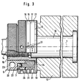
- the elastic flange 18 only acts on the tool 12 in an annular region a, the outer boundary 8 of which is approximately the outer circumference of the flange 18 and the inner boundary 9 a predetermined radial distance from the sleeve 16 has.
- a pair of adjusting disks 19, 21, which can also be configured as adjusting rings, are arranged between the threaded ring 26 and the resilient flange 18.
- the mutually facing plane surfaces 15, 17 of these adjusting disks 19, 21 have a precisely predetermined, ie predetermined, non-parallelism in that these surfaces run obliquely to one another.
- a desired non-parallelism of the plane surfaces facing away from one another can be precisely set by mutually rotating these disks 19, 21. Since the non-parallelism is only a few thousandths of a millimeter - that is, in the »range - it could not be shown in the drawings.
- the adjusting disks 19, 21 shows a marked zero position, shown schematically in the drawing, in which the two disks together have the same thickness at each point and in which the receiving openings 31 on the outer circumference of the two disks are parallel to one another.
- the disks can be rotated in the direction of the arrows, so that the disks can be adjusted with the aid of a scale 13, which can be attached to the radial flange 18, to align the concentricity of the tool 12 in the exactly correct position.
Landscapes
- Engineering & Computer Science (AREA)
- Mechanical Engineering (AREA)
- General Engineering & Computer Science (AREA)
- Gripping On Spindles (AREA)
- Gear Processing (AREA)
Claims (12)
- Dispositif de serrage hydraulique pour le serrage axial de solides de révolution (12), de pièces, outils, ou autres, en forme de disques ou de cylindres, par exemple, sur une broche rotative (10), avec un corps de base (20) fixé sur la broche, et avec un piston annulaire (24) flottant dans le corps de base, ce piston pouvant être déplacé dans le sens axial par rapport au corps de base, par l'intermédiaire d'un système hydraulique fermé en soi, au moyen d'éléments de pression, de vis de pression (23) par exemple, et serrant fermement la pièce ou l'outil (12) dans le sens axial, caractérisé par un élément élastique (18), assemblé avec le corps de base (20), sollicité par le piston annulaire flottant (24), d'une part, et pouvant s'appliquer contre l'outil (12), d'autre part.
- Dispositif de serrage suivant la revendication 1, caractérisé en ce que l'élément élastique est réalisé sous forme de bride élastique (18).
- Dispositif de serrage suivant l'une des revendications 1 et 2, caractérisé en ce que la bride élastique (18) est prévue sur une douille (16), serrée avec la broche (10).
- Dispositif de serrage suivant l'une quelconque des revendications 1 à 3, caractérisé en ce qu'une bague filetée (26), qui exerce une pression axiale contre la bride élastique (18), est vissée sur le corps de base (20), de sorte que la force axiale, exercée sur l'outil (12), reste maintenue même après le soulagement du piston annulaire hydraulique (24) (figure 2).
- Dispositif de serrage suivant la revendication 4, caractérisé en ce qu'une bague de pression conique (28) est prévue entre la bague filetée (26) et la bride élastique (18), cette bague présentant un jeu radial (s) et son côté, tourné vers la bride (18), ayant une réalisation cunéiforme et/ou conique, de sorte que la section transversale forme une clavette orientée en direction de l'axe médian (1), et en ce que des moyens de réglage (32) sont prévus pour déplacer la bague de pression (28) dans le sens radial, un déplacement correspondant de la bride (18) pouvant être de ce fait obtenu.
- Dispositif de serrage suivant la revendication 5, caractérisé en ce que la bague filetée (26) enserre la bague de pression conique (28) par une collerette (27), et en ce qu'une vis de pression, au moins, plusieurs vis de pression (32) de préférence, qui agissent sur la bague de pression conique (28), dont elles permettent le déplacement radial, sont prévues dans cette collerette (27).
- Dispositif de serrage suivant l'une des revendications 5 et 6, caractérisé en ce que la bague de pression conique (28) est centrée par rapport au piston annulaire (24) par une bague élastique (30), un joint torique de préférence.
- Dispositif de serrage suivant l'une quelconque ou plusieurs des revendications 1 à 7, caractérisé en ce que la bride élastique (18) ne sollicite l'outil (12) que dans une zone (a) en forme d'anneau de cercle, dont la délimitation externe (8) correspond à peu près au pourtour externe de la bride (18), et dont la délimitation interne (9) présente une distance radiale par rapport à la douille (16).
- Dispositif de serrage suivant l'une quelconque ou plusieurs des revendications 1 à 8, caractérisé en ce qu'une paire de disques de réglage (19, 21), pouvant être tournés l'un par rapport à l'autre, est prévue entre la bague filetée (26) et la bride élastique (18), les surfaces planes (15, 17) de ces disques présentant un défaut de parallélisme mutuel, d'une valeur prédéfinie, de sorte qu'une rotation mutuelle des disques de réglage (19, 21) permet de régler un défaut de parallèlisme défini des surfaces planes, opposées l'une à l'autre, pour un réglage précis des erreurs de fauxronds.
- Dispositif de serrage suivant la revendication 9, caractérisé en ce que les disques de réglage (19, 21) présentent un repère de réglage, prévu de préférence sur la bride (18).
- Dispositif de serrage suivant l'une des revendications 9 et 10, caractérisé en ce que les disques de réglage (19, 21) présentent sur leur pourtour externe des ouvertures de réception (31) pour un outil de torsion insérable.
- Dispositif de serrage suivant l'une quelconque des revendications 1 à 3, caractérisé en ce que la douille (16) est vissée sur le corps de base (20).
Applications Claiming Priority (2)
| Application Number | Priority Date | Filing Date | Title |
|---|---|---|---|
| DE3941765 | 1989-12-18 | ||
| DE3941765A DE3941765A1 (de) | 1989-12-18 | 1989-12-18 | Hydraulisches spannelement |
Publications (3)
| Publication Number | Publication Date |
|---|---|
| EP0433925A2 EP0433925A2 (fr) | 1991-06-26 |
| EP0433925A3 EP0433925A3 (en) | 1992-07-29 |
| EP0433925B1 true EP0433925B1 (fr) | 1994-06-08 |
Family
ID=6395707
Family Applications (1)
| Application Number | Title | Priority Date | Filing Date |
|---|---|---|---|
| EP90124298A Expired - Lifetime EP0433925B1 (fr) | 1989-12-18 | 1990-12-15 | Dispositif de serrage hydraulique |
Country Status (4)
| Country | Link |
|---|---|
| US (1) | US5125776A (fr) |
| EP (1) | EP0433925B1 (fr) |
| JP (1) | JP3154499B2 (fr) |
| DE (2) | DE3941765A1 (fr) |
Cited By (1)
| Publication number | Priority date | Publication date | Assignee | Title |
|---|---|---|---|---|
| CN111360714A (zh) * | 2018-12-25 | 2020-07-03 | 河南铁福来装备制造股份有限公司 | 一种液压抱紧装置 |
Families Citing this family (25)
| Publication number | Priority date | Publication date | Assignee | Title |
|---|---|---|---|---|
| US5336727A (en) * | 1990-07-16 | 1994-08-09 | Tosoh Corporation | Maleic anhydride copolymer |
| DE4201394C2 (de) * | 1992-01-21 | 1994-02-10 | Manfred Baur | Hydraulisches Spannelement |
| DE4214000C1 (en) * | 1992-04-29 | 1993-07-22 | Man Gutehoffnungshuette Ag, 4200 Oberhausen, De | Reusable releasable connection device - used e.g. on heated vessels and components in smelting works |
| DE4317502A1 (de) * | 1993-05-26 | 1994-12-01 | Schrem Werkzeugfab Albert | Hydraulisches Spannelement |
| DE4328025A1 (de) * | 1993-08-20 | 1995-02-23 | Manfred Baur | Spannvorrichtung zum Einspannen eines Werkzeuges |
| IT1268861B1 (it) * | 1994-12-20 | 1997-03-13 | Femas Srl | Ghiera di bloccaggio per alberi rotanti |
| US6299179B1 (en) | 1995-03-22 | 2001-10-09 | R. S. R. Adtec Ltd. | Fluid actuated chuck |
| US6390723B1 (en) * | 1996-10-05 | 2002-05-21 | Schaefer Erhard | Changing device for shaft/hub connections |
| DE29711184U1 (de) * | 1997-06-26 | 1997-08-21 | Gebr. Leitz GmbH & Co, 73447 Oberkochen | Hydro-Spannelement |
| US5954346A (en) * | 1997-09-29 | 1999-09-21 | Boart Longyear Inc. | Hydraulic chuck |
| US6286584B1 (en) | 1998-07-15 | 2001-09-11 | James A. Frields | Quick-change mechanism for a tie bar |
| DE19860403B4 (de) * | 1998-12-28 | 2004-03-25 | Wilhelm Fette Gmbh | Anordnung aus Wälzfräskörper und Aufnahmedorn |
| DE19937436A1 (de) * | 1999-08-07 | 2001-02-08 | Schaeffler Waelzlager Ohg | Spanneinrichtung zum lösbaren Befestigen eines Teils auf einer Welle |
| CN100344407C (zh) * | 2000-04-10 | 2007-10-24 | 帕斯卡工程株式会社 | 工具夹 |
| US6719303B2 (en) | 2001-10-26 | 2004-04-13 | Boart Longyear International Holdings, Inc. | Drill string chuck |
| DE102004018736B4 (de) * | 2004-04-17 | 2006-03-16 | Airbus Deutschland Gmbh | Verbindungselement |
| JP4576357B2 (ja) * | 2006-06-02 | 2010-11-04 | 有限会社信立 | ワークのかさ上げ治具 |
| US7341017B2 (en) * | 2006-06-07 | 2008-03-11 | J&J Machine & Tool, Inc. | Hydraulically locked boat accessory mounting device |
| DE102008034233B3 (de) * | 2008-07-23 | 2009-10-22 | Metabowerke Gmbh | Handwerkzeuggerät mit einem rotierend antreibbaren, flächenhaften Werkzeug und einer Spannmutter |
| DE102010008371A1 (de) * | 2010-02-17 | 2011-08-18 | Wolf, Michael, 89518 | Hydraulisches Spannelement |
| DE102010040784A1 (de) * | 2010-09-15 | 2012-03-15 | Aktiebolaget Skf | Spannvorrichtung |
| CN103990995A (zh) * | 2014-05-22 | 2014-08-20 | 昆明水泵厂 | 用于加工is泵泵盖的可调高效工装法兰及其加工方法 |
| DE102018113747B4 (de) * | 2018-06-08 | 2023-05-11 | Schöning Gmbh | Unterwasser-Bearbeitungsmaschine mit einem Werkzeughalter mit einer Wechselnabe für die Aufnahme von Rotationswerkzeugen |
| DE102019215695B4 (de) * | 2019-10-11 | 2025-07-24 | Kennametal Inc. | Dichtkolben für eine hydraulische Werkzeughalterung und hydraulische Werkzeughalterung |
| US12063926B2 (en) | 2021-02-05 | 2024-08-20 | Fourth Arrow, LLC | Mounting brackets and utility mount |
Family Cites Families (7)
| Publication number | Priority date | Publication date | Assignee | Title |
|---|---|---|---|---|
| US3033597A (en) * | 1960-08-08 | 1962-05-08 | Frederick L B Miller | Means for mounting and dismounting gears and the like on shafting |
| CH412526A (de) * | 1963-02-12 | 1966-04-30 | Albert Schrem Fa | Hydraulisches Spannelement |
| DE2544498C3 (de) * | 1975-10-04 | 1981-05-21 | Spieth-Maschinenelemente Gmbh & Co Kg, 7300 Esslingen | Gewindering |
| DE3038549A1 (de) * | 1980-10-11 | 1982-05-19 | Albert Schrem Werkzeugfabrik GmbH, 7928 Giengen | Ausgleichscheibe |
| DE3422000A1 (de) * | 1984-06-14 | 1985-12-19 | Albert Schrem Werkzeugfabrik GmbH, 7928 Giengen | Druckmittelbetaetigte spannvorrichtung zum spannen von werkzeugen oder werkstuecken |
| US4953877A (en) * | 1988-09-23 | 1990-09-04 | Gene Slachta | Fluid actuated chuck |
| WO2013046508A1 (fr) | 2011-09-27 | 2013-04-04 | テルモ株式会社 | Système d'évaluation de fonction motrice, dispositif de traitement d'informations et procédé de traitement d'informations |
-
1989
- 1989-12-18 DE DE3941765A patent/DE3941765A1/de not_active Withdrawn
-
1990
- 1990-12-15 EP EP90124298A patent/EP0433925B1/fr not_active Expired - Lifetime
- 1990-12-15 DE DE59006042T patent/DE59006042D1/de not_active Expired - Fee Related
- 1990-12-17 JP JP40272290A patent/JP3154499B2/ja not_active Expired - Fee Related
- 1990-12-18 US US07/631,007 patent/US5125776A/en not_active Expired - Lifetime
Cited By (1)
| Publication number | Priority date | Publication date | Assignee | Title |
|---|---|---|---|---|
| CN111360714A (zh) * | 2018-12-25 | 2020-07-03 | 河南铁福来装备制造股份有限公司 | 一种液压抱紧装置 |
Also Published As
| Publication number | Publication date |
|---|---|
| EP0433925A2 (fr) | 1991-06-26 |
| EP0433925A3 (en) | 1992-07-29 |
| DE59006042D1 (de) | 1994-07-14 |
| JPH04111737A (ja) | 1992-04-13 |
| US5125776A (en) | 1992-06-30 |
| DE3941765A1 (de) | 1991-06-20 |
| JP3154499B2 (ja) | 2001-04-09 |
Similar Documents
| Publication | Publication Date | Title |
|---|---|---|
| EP0433925A2 (fr) | Dispositif de serrage hydraulique | |
| EP0111092B1 (fr) | Dispositif d'accouplement | |
| DE69800037T2 (de) | Spannfutter | |
| EP0182290A2 (fr) | Tête de fraisage | |
| DE4315839C2 (de) | Werkstückspannvorrichtung für Mehrseitenbearbeitung | |
| EP0451360A2 (fr) | Dispositif de serrage pour la fixation d'un outil dans un porte-outil | |
| DE2744410A1 (de) | 4-backen-spannfutter fuer ein werkstueck | |
| DE69712972T2 (de) | Schmiedewerkzeug für den Einbau von Lagern | |
| DE3422000A1 (de) | Druckmittelbetaetigte spannvorrichtung zum spannen von werkzeugen oder werkstuecken | |
| EP0164582A1 (fr) | Mandrin pour le montage centré de pièces en rotation | |
| EP0630721B1 (fr) | Dispositif de serrage hydraulique | |
| EP0943384B1 (fr) | Dispositif de serrage | |
| DE19917146A1 (de) | Nullpunktspannsystem | |
| DE10163365B4 (de) | Spannfutter zum Festspannen dünner, scheibenförmiger Werkstücke | |
| DE2434859C3 (de) | Spannvorrichtung zum Spannen eines Werkstückes | |
| DE4339755C1 (de) | Vorrichtung zum Einbringen von Bohrungen in eine Schüssel bzw. einer Felge eines Rades eines Kraftfahrzeuges | |
| EP0355305B1 (fr) | Fraise disque | |
| EP3623088B1 (fr) | Dispositif de serrage des pièces à usiner | |
| EP2219811A2 (fr) | Dispositif pour serrer un porte-outil sur un mandrin de serrage pouvant être fixé sur une machine d'usinage | |
| EP0366105A2 (fr) | Dispositif de fixation pour outil, en particulier pour meules de rectification | |
| DE4041683A1 (de) | Hydraulisches spannelement | |
| EP0153560A2 (fr) | Dispositif de serrage | |
| DE69112116T2 (de) | Unterstützungsvorrichtung für eine Trommel. | |
| EP0275911B1 (fr) | Dispositif d'accouplement de deux pièces à rotation symétrique par exemple une tête d'outil et un porte-outil dans des machines-outils | |
| EP0173862A2 (fr) | Appareil pour faire des cannelures dans des pièces, de préférence dans des pièces cylindriques |
Legal Events
| Date | Code | Title | Description |
|---|---|---|---|
| PUAI | Public reference made under article 153(3) epc to a published international application that has entered the european phase |
Free format text: ORIGINAL CODE: 0009012 |
|
| AK | Designated contracting states |
Kind code of ref document: A2 Designated state(s): DE FR GB IT |
|
| PUAL | Search report despatched |
Free format text: ORIGINAL CODE: 0009013 |
|
| AK | Designated contracting states |
Kind code of ref document: A3 Designated state(s): DE FR GB IT |
|
| 17P | Request for examination filed |
Effective date: 19921014 |
|
| 17Q | First examination report despatched |
Effective date: 19930831 |
|
| GRAA | (expected) grant |
Free format text: ORIGINAL CODE: 0009210 |
|
| AK | Designated contracting states |
Kind code of ref document: B1 Designated state(s): DE FR GB IT |
|
| REF | Corresponds to: |
Ref document number: 59006042 Country of ref document: DE Date of ref document: 19940714 |
|
| ET | Fr: translation filed | ||
| ITF | It: translation for a ep patent filed | ||
| GBT | Gb: translation of ep patent filed (gb section 77(6)(a)/1977) |
Effective date: 19940914 |
|
| PLBE | No opposition filed within time limit |
Free format text: ORIGINAL CODE: 0009261 |
|
| STAA | Information on the status of an ep patent application or granted ep patent |
Free format text: STATUS: NO OPPOSITION FILED WITHIN TIME LIMIT |
|
| 26N | No opposition filed | ||
| REG | Reference to a national code |
Ref country code: GB Ref legal event code: IF02 |
|
| PGFP | Annual fee paid to national office [announced via postgrant information from national office to epo] |
Ref country code: IT Payment date: 20081223 Year of fee payment: 19 |
|
| PGFP | Annual fee paid to national office [announced via postgrant information from national office to epo] |
Ref country code: FR Payment date: 20081212 Year of fee payment: 19 |
|
| PGFP | Annual fee paid to national office [announced via postgrant information from national office to epo] |
Ref country code: DE Payment date: 20081219 Year of fee payment: 19 |
|
| PGFP | Annual fee paid to national office [announced via postgrant information from national office to epo] |
Ref country code: GB Payment date: 20081216 Year of fee payment: 19 |
|
| GBPC | Gb: european patent ceased through non-payment of renewal fee |
Effective date: 20091215 |
|
| REG | Reference to a national code |
Ref country code: FR Ref legal event code: ST Effective date: 20100831 |
|
| PG25 | Lapsed in a contracting state [announced via postgrant information from national office to epo] |
Ref country code: FR Free format text: LAPSE BECAUSE OF NON-PAYMENT OF DUE FEES Effective date: 20091231 |
|
| PG25 | Lapsed in a contracting state [announced via postgrant information from national office to epo] |
Ref country code: DE Free format text: LAPSE BECAUSE OF NON-PAYMENT OF DUE FEES Effective date: 20100701 |
|
| PG25 | Lapsed in a contracting state [announced via postgrant information from national office to epo] |
Ref country code: GB Free format text: LAPSE BECAUSE OF NON-PAYMENT OF DUE FEES Effective date: 20091215 |
|
| PG25 | Lapsed in a contracting state [announced via postgrant information from national office to epo] |
Ref country code: IT Free format text: LAPSE BECAUSE OF NON-PAYMENT OF DUE FEES Effective date: 20091215 |