EP0434002A2 - Circuit pour installation d'alimentations électriques sans interruption - Google Patents
Circuit pour installation d'alimentations électriques sans interruption Download PDFInfo
- Publication number
- EP0434002A2 EP0434002A2 EP19900124624 EP90124624A EP0434002A2 EP 0434002 A2 EP0434002 A2 EP 0434002A2 EP 19900124624 EP19900124624 EP 19900124624 EP 90124624 A EP90124624 A EP 90124624A EP 0434002 A2 EP0434002 A2 EP 0434002A2
- Authority
- EP
- European Patent Office
- Prior art keywords
- windings
- transformer
- mains
- power supply
- circuit arrangement
- Prior art date
- Legal status (The legal status is an assumption and is not a legal conclusion. Google has not performed a legal analysis and makes no representation as to the accuracy of the status listed.)
- Granted
Links
Images
Classifications
-
- H—ELECTRICITY
- H02—GENERATION; CONVERSION OR DISTRIBUTION OF ELECTRIC POWER
- H02J—ELECTRIC POWER NETWORKS; CIRCUIT ARRANGEMENTS OR SYSTEMS FOR SUPPLYING OR DISTRIBUTING ELECTRIC POWER; SYSTEMS FOR STORING ELECTRIC ENERGY
- H02J9/00—Circuit arrangements for emergency or stand-by power supply, e.g. for emergency lighting
- H02J9/04—Circuit arrangements for emergency or stand-by power supply, e.g. for emergency lighting in which the distribution system is disconnected from the normal source and connected to a standby source
- H02J9/06—Circuit arrangements for emergency or stand-by power supply, e.g. for emergency lighting in which the distribution system is disconnected from the normal source and connected to a standby source with automatic change-over, e.g. UPS systems
- H02J9/062—Circuit arrangements for emergency or stand-by power supply, e.g. for emergency lighting in which the distribution system is disconnected from the normal source and connected to a standby source with automatic change-over, e.g. UPS systems for AC powered loads
-
- Y—GENERAL TAGGING OF NEW TECHNOLOGICAL DEVELOPMENTS; GENERAL TAGGING OF CROSS-SECTIONAL TECHNOLOGIES SPANNING OVER SEVERAL SECTIONS OF THE IPC; TECHNICAL SUBJECTS COVERED BY FORMER USPC CROSS-REFERENCE ART COLLECTIONS [XRACs] AND DIGESTS
- Y02—TECHNOLOGIES OR APPLICATIONS FOR MITIGATION OR ADAPTATION AGAINST CLIMATE CHANGE
- Y02B—CLIMATE CHANGE MITIGATION TECHNOLOGIES RELATED TO BUILDINGS, e.g. HOUSING, HOUSE APPLIANCES OR RELATED END-USER APPLICATIONS
- Y02B70/00—Technologies for an efficient end-user side electric power management and consumption
- Y02B70/30—Systems integrating technologies related to power network operation and communication or information technologies for improving the carbon footprint of the management of residential or tertiary loads, i.e. smart grids as climate change mitigation technology in the buildings sector, including also the last stages of power distribution and the control, monitoring or operating management systems at local level
-
- Y—GENERAL TAGGING OF NEW TECHNOLOGICAL DEVELOPMENTS; GENERAL TAGGING OF CROSS-SECTIONAL TECHNOLOGIES SPANNING OVER SEVERAL SECTIONS OF THE IPC; TECHNICAL SUBJECTS COVERED BY FORMER USPC CROSS-REFERENCE ART COLLECTIONS [XRACs] AND DIGESTS
- Y04—INFORMATION OR COMMUNICATION TECHNOLOGIES HAVING AN IMPACT ON OTHER TECHNOLOGY AREAS
- Y04S—SYSTEMS INTEGRATING TECHNOLOGIES RELATED TO POWER NETWORK OPERATION, COMMUNICATION OR INFORMATION TECHNOLOGIES FOR IMPROVING THE ELECTRICAL POWER GENERATION, TRANSMISSION, DISTRIBUTION, MANAGEMENT OR USAGE, i.e. SMART GRIDS
- Y04S20/00—Management or operation of end-user stationary applications or the last stages of power distribution; Controlling, monitoring or operating thereof
- Y04S20/20—End-user application control systems
Definitions
- the invention relates to a circuit arrangement for the construction of uninterruptible power supply units with the features of the preamble of claim 1.
- the structure of a current-fed push-pull converter is known.
- the current-fed push-pull converter has a mains transformer with two primary windings and a choke coil connected in series with the mains transformer with a freewheeling diode. Only two diodes and a smoothing capacitor are required for the output circuits.
- the output circuits are each connected to partial windings of a symmetrically constructed secondary winding of the mains transformer.
- the object of the invention is to provide a circuit arrangement for the construction of uninterruptible power supply units, by means of which the effort for the formation of uninterruptible power supply units becomes less than the effort required to form power supply units constructed according to the principles described at the beginning.
- the basis for the circuit arrangement is a current-fed push-pull converter.
- the input circuit is simulated a second time on the basis of the rectified AC mains voltage, there being two options for connection to the mains transformer.
- the first option is to connect the second input circuit via second primary windings.
- the second possibility which is an advantageous further development of the invention, is to connect the second input circuit via corresponding secondary windings from those already present for the output circuits. With the second connection option, the second primary windings are omitted.
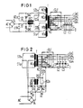
- FIG. 1 shows a power supply unit which is based on a switching power supply which operates on the principle of a current-fed push-pull converter.
- An AC line voltage AG is fed to the switching power supply on the input side, which is converted into the DC input voltage U1 via a rectifier GL.
- the input DC voltage U1 is applied to the center tap of two further controlled switches S1a and S1b, which in turn are connected in parallel, via a series-connected controlled switch S1 and a series choke coil DS1 two primary windings N1a and N1b of a network transformer T connected in series with one another are arranged.
- the center tap of the two primary windings N1a and N1b connected in series with one another is connected directly to the other side of the rectifier GL.
- a diode DA1 is connected in such a way that, when switch S1 is closed, it is poled in the reverse direction and parallel to the input DC voltage U1.
- the mains transformer T has on its secondary side a secondary winding N3 constructed symmetrically to a center tap, with several partial taps belonging together in pairs, each for an output voltage. In each case the two ends of a partial winding which are symmetrical with respect to the center tap are connected together via a diode and each lead to one of four outputs of the circuit arrangement according to the exemplary embodiment.
- the diodes in question are combined in the rectifier field GLF.
- One of four output capacitors C1 to C4 is connected between the respective output of the switching power supply and the center tap of the secondary winding N3.
- the DC output voltages Ua1 to Ua4 can be tapped at the outputs of the switching
- the network transformer T serves, inter alia, as a network disconnection device.
- the mains transformer T has two further primary windings N2a and N2b, which are connected to a DC voltage source U2 via controlled switches S2, S2a and S2b and an upstream choke coil DS2.
- the connection is such that in normal operation of the power supply unit, that is to say in the presence of the regular AC mains voltage, the effect from the primary to the secondary side of the mains transformer T in the fault mode, i.e. in the event of failure of the regular AC mains voltage, the other primary windings N2a and N2b start.
- the activation of the switches S2a and S2b corresponds to that of the controlled switches S1a and S1b with respect to the regular primary circuit.
- the regular primary circuit is simulated by the additional components starting from the DC input voltage U1, which is provided by the DC voltage source U2 in the fault mode. Therefore, an additional diode DA2 is provided, which performs the same function as the diode DA1 in the regular primary circuit. If the AC mains voltage AG fails, the regular primary circuit is replaced by the second primary circuit, as a result of which the DC output voltages Ua1 to Ua4 are maintained.
- the power supply unit according to FIG 2 corresponds to that of FIG 1, with the difference that instead of additional primary windings, the secondary windings already present on the secondary side of the mains transformer T for the output circuits are used for feeding in a correspondingly prepared alternative energy.
- the substitute energy must be fed into those secondary windings which, due to their physical nature, are suitable for transferring the energy required by the other secondary windings.
- the battery current flowing through the choke coil DS2 is fed directly into corresponding partial windings of the secondary winding N3 via the push-pull switches S2a and S2b. According to FIG 2, this happens over the second partial windings, ie over those partial windings which are responsible for generating the second output voltage, namely Ua2.
- the DC output voltages Ua1 to Ua4 are generated inductively via the mains transformer T in the correct division ratio of the individual secondary windings to one another.
- the polarity of the direct voltage source U2 and the diode DA2 could also be chosen in reverse.
Landscapes
- Business, Economics & Management (AREA)
- Emergency Management (AREA)
- Engineering & Computer Science (AREA)
- Power Engineering (AREA)
- Stand-By Power Supply Arrangements (AREA)
- Dc-Dc Converters (AREA)
- Selective Calling Equipment (AREA)
- Direct Current Feeding And Distribution (AREA)
- Emergency Protection Circuit Devices (AREA)
- Supply And Distribution Of Alternating Current (AREA)
Applications Claiming Priority (2)
| Application Number | Priority Date | Filing Date | Title |
|---|---|---|---|
| DE3942427A DE3942427A1 (de) | 1989-12-21 | 1989-12-21 | Schaltungsanordnung zum aufbau unterbrechungsfreier stromversorgungseinheiten |
| DE3942427 | 1989-12-21 |
Publications (3)
| Publication Number | Publication Date |
|---|---|
| EP0434002A2 true EP0434002A2 (fr) | 1991-06-26 |
| EP0434002A3 EP0434002A3 (en) | 1992-10-07 |
| EP0434002B1 EP0434002B1 (fr) | 1995-03-08 |
Family
ID=6396102
Family Applications (1)
| Application Number | Title | Priority Date | Filing Date |
|---|---|---|---|
| EP90124624A Expired - Lifetime EP0434002B1 (fr) | 1989-12-21 | 1990-12-18 | Circuit pour installation d'alimentations électriques sans interruption |
Country Status (4)
| Country | Link |
|---|---|
| EP (1) | EP0434002B1 (fr) |
| AT (1) | ATE119720T1 (fr) |
| DE (2) | DE3942427A1 (fr) |
| ES (1) | ES2068984T3 (fr) |
Cited By (1)
| Publication number | Priority date | Publication date | Assignee | Title |
|---|---|---|---|---|
| CN103595120A (zh) * | 2013-11-21 | 2014-02-19 | 长园深瑞继保自动化有限公司 | 多进线备用电源自动投入方法 |
Families Citing this family (3)
| Publication number | Priority date | Publication date | Assignee | Title |
|---|---|---|---|---|
| CH684510A5 (de) * | 1992-12-18 | 1994-09-30 | Frako Kondensator Apparate | Durch eine Batterie unterbruchfrei gestütztes Schaltnetzteil. |
| DE4319508A1 (de) * | 1993-06-12 | 1994-12-15 | Theo Benning Elektrotechnik Gm | Schutzschaltung |
| DE19613831C1 (de) * | 1996-04-06 | 1997-11-27 | Aeg Stromversorgungs Syst Gmbh | Anlage zur unterbrechungsfreien Stromversorgung |
Family Cites Families (9)
| Publication number | Priority date | Publication date | Assignee | Title |
|---|---|---|---|---|
| GB1127909A (en) * | 1965-12-30 | 1968-09-18 | Trw Inc | Improvements in or relating to electricity stand-by generating systems |
| DE2462290C3 (de) * | 1974-10-10 | 1979-07-26 | Siemens Ag, 1000 Berlin Und 8000 Muenchen | Schaltungsanordnung zur unterbrechungsfreien Stromversorgung eines Verbrauchers |
| US4038559A (en) * | 1976-01-23 | 1977-07-26 | Bell Telephone Laboratories, Incorporated | Regulated uninterruptible power supply |
| DE3118909C2 (de) * | 1981-05-13 | 1983-02-10 | Deutsche Automobilgesellschaft Mbh, 3000 Hannover | Unterbrechungsfreie Stromversorgung für Gleichstromverbraucher |
| DE3246930C2 (de) * | 1982-12-15 | 1987-02-19 | Licentia Patent-Verwaltungs-Gmbh, 6000 Frankfurt | Verfahren und Anordnung zum Umschalten eines Verbrauchers von einem elektrischen Netz auf ein Stromversorgungsaggregat |
| DE3410684A1 (de) * | 1984-03-23 | 1985-10-03 | Dieter Gräßlin Feinwerktechnik, 7742 St Georgen | Elektronisch gesteuerter induktiver spannungswandler |
| DE3419792A1 (de) * | 1984-05-26 | 1985-11-28 | Grundig E.M.V. Elektro-Mechanische Versuchsanstalt Max Grundig holländ. Stiftung & Co KG, 8510 Fürth | Schaltnetzteil nach dem sperrwandlerprinzip fuer den wahlweisen betrieb an netz- oder einer batteriespannung |
| DE3636346A1 (de) * | 1986-10-25 | 1988-04-28 | Philips Patentverwaltung | Schaltungsanordnung zur energieversorgung einer last |
| DE3736372C1 (de) * | 1987-10-27 | 1989-01-05 | Nixdorf Computer Ag | Schaltnetzteil |
-
1989
- 1989-12-21 DE DE3942427A patent/DE3942427A1/de active Granted
-
1990
- 1990-12-18 DE DE59008641T patent/DE59008641D1/de not_active Expired - Fee Related
- 1990-12-18 AT AT90124624T patent/ATE119720T1/de not_active IP Right Cessation
- 1990-12-18 ES ES90124624T patent/ES2068984T3/es not_active Expired - Lifetime
- 1990-12-18 EP EP90124624A patent/EP0434002B1/fr not_active Expired - Lifetime
Cited By (2)
| Publication number | Priority date | Publication date | Assignee | Title |
|---|---|---|---|---|
| CN103595120A (zh) * | 2013-11-21 | 2014-02-19 | 长园深瑞继保自动化有限公司 | 多进线备用电源自动投入方法 |
| CN103595120B (zh) * | 2013-11-21 | 2015-11-18 | 长园深瑞继保自动化有限公司 | 多进线备用电源自动投入方法 |
Also Published As
| Publication number | Publication date |
|---|---|
| ES2068984T3 (es) | 1995-05-01 |
| DE3942427C2 (fr) | 1993-01-21 |
| EP0434002B1 (fr) | 1995-03-08 |
| DE59008641D1 (de) | 1995-04-13 |
| EP0434002A3 (en) | 1992-10-07 |
| ATE119720T1 (de) | 1995-03-15 |
| DE3942427A1 (de) | 1991-06-27 |
Similar Documents
| Publication | Publication Date | Title |
|---|---|---|
| DE102007028077B4 (de) | Vorrichtung zur Einspeisung elektrischer Energie in ein Energieversorgungsnetz und Gleichspannungswandler für eine solche Vorrichtung | |
| EP2030299B1 (fr) | Onduleur destiné à injecter de l'énergie électrique dans un réseau de distribution d'énergie | |
| DE69818298T2 (de) | Frequenzwandler und unterbrechungsfreie stromversorgung damit | |
| DE102007038960A1 (de) | Wechselrichter | |
| DE102010060508B4 (de) | Spannungswandler mit einer Speicherdrossel mit einer Wicklung und einer Speicherdrossel mit zwei Wicklungen | |
| EP0521901A1 (fr) | Dispositif d'alimentation ininterrompue en courant electrique. | |
| DE4342327C2 (de) | Durch eine Batterie unterbruchfrei gestütztes Schaltnetzteil | |
| DE102010013138A1 (de) | Schaltungsanordnung und Verfahren zur Erzeugung einer Wechselspannung aus einer Mehrzahl von Spannungsquellen mit zeitlich variabler Ausgangsgleichspannung | |
| EP2339730A1 (fr) | Convertisseur CC/CC pouvant être relié à la terre | |
| EP0434002B1 (fr) | Circuit pour installation d'alimentations électriques sans interruption | |
| EP1085646A1 (fr) | Convertisseur DC/DC | |
| DE102018200874A1 (de) | Bidirektionaler Gleichspannungswandler sowie Verfahren zum Betreiben eines bidirektionalen Gleichspannungswandlers | |
| EP0455062B1 (fr) | Convertisseur push-pull alimenté en courant | |
| AT399432B (de) | Sperrwandler | |
| EP1754305B1 (fr) | Procede pour faire fonctionner un onduleur a commande electronique et dispositif pour realiser ce procede | |
| DE102018209139A1 (de) | Wechselspannungs-Ladevorrichtung | |
| DE10138751B4 (de) | Wechselrichter mit schnellschaltenden ansteuerbaren elektronischen Schaltern, insbesondere IGBT-Schaltern, sowie Verfahren zur Ansteuerung eines derartigen Wechselrichters | |
| WO2013064318A2 (fr) | Convertisseur de tension comportant un premier circuit parallèle | |
| EP4238210B1 (fr) | Convertisseur continu-continu pour la symétrisation d'un circuit intermédiaire | |
| DE19646626A1 (de) | Anordnung zur Stromversorgung einer Last sowie Verwendung | |
| WO2000045185A2 (fr) | Regulateur de tension continue bidirectionnel | |
| WO1999063651A1 (fr) | Dispositif de symetrie | |
| DE102015113071B4 (de) | Potentialverschiebende Halbbrücke, Polwender und blindleistungsfähiger Wechselrichter sowie Polwendeverfahren | |
| AT511299B1 (de) | Zweiquadrantenstellglied und transformatorloser koppelkonverter für stark unterschiedliche gleichspannungen | |
| EP0429016A1 (fr) | Alimentation |
Legal Events
| Date | Code | Title | Description |
|---|---|---|---|
| PUAI | Public reference made under article 153(3) epc to a published international application that has entered the european phase |
Free format text: ORIGINAL CODE: 0009012 |
|
| 17P | Request for examination filed |
Effective date: 19901218 |
|
| AK | Designated contracting states |
Kind code of ref document: A2 Designated state(s): AT BE CH DE ES FR GB IT LI NL SE |
|
| PUAL | Search report despatched |
Free format text: ORIGINAL CODE: 0009013 |
|
| AK | Designated contracting states |
Kind code of ref document: A3 Designated state(s): AT BE CH DE ES FR GB IT LI NL SE |
|
| RAP3 | Party data changed (applicant data changed or rights of an application transferred) |
Owner name: SIEMENS NIXDORF INFORMATIONSSYSTEME AG |
|
| 17Q | First examination report despatched |
Effective date: 19931115 |
|
| GRAA | (expected) grant |
Free format text: ORIGINAL CODE: 0009210 |
|
| AK | Designated contracting states |
Kind code of ref document: B1 Designated state(s): AT BE CH DE ES FR GB IT LI NL SE |
|
| REF | Corresponds to: |
Ref document number: 119720 Country of ref document: AT Date of ref document: 19950315 Kind code of ref document: T |
|
| REF | Corresponds to: |
Ref document number: 59008641 Country of ref document: DE Date of ref document: 19950413 |
|
| REG | Reference to a national code |
Ref country code: ES Ref legal event code: FG2A Ref document number: 2068984 Country of ref document: ES Kind code of ref document: T3 |
|
| ITF | It: translation for a ep patent filed | ||
| GBT | Gb: translation of ep patent filed (gb section 77(6)(a)/1977) |
Effective date: 19950517 |
|
| ET | Fr: translation filed | ||
| PG25 | Lapsed in a contracting state [announced via postgrant information from national office to epo] |
Ref country code: GB Effective date: 19951218 Ref country code: AT Effective date: 19951218 |
|
| PG25 | Lapsed in a contracting state [announced via postgrant information from national office to epo] |
Ref country code: SE Effective date: 19951219 |
|
| PG25 | Lapsed in a contracting state [announced via postgrant information from national office to epo] |
Ref country code: LI Effective date: 19951231 Ref country code: CH Effective date: 19951231 Ref country code: BE Effective date: 19951231 |
|
| PLBE | No opposition filed within time limit |
Free format text: ORIGINAL CODE: 0009261 |
|
| STAA | Information on the status of an ep patent application or granted ep patent |
Free format text: STATUS: NO OPPOSITION FILED WITHIN TIME LIMIT |
|
| 26N | No opposition filed | ||
| BERE | Be: lapsed |
Owner name: SIEMENS NIXDORF INFORMATIONSSYSTEME A.G. Effective date: 19951231 |
|
| PG25 | Lapsed in a contracting state [announced via postgrant information from national office to epo] |
Ref country code: NL Effective date: 19960701 |
|
| GBPC | Gb: european patent ceased through non-payment of renewal fee |
Effective date: 19951218 |
|
| REG | Reference to a national code |
Ref country code: CH Ref legal event code: PL |
|
| PG25 | Lapsed in a contracting state [announced via postgrant information from national office to epo] |
Ref country code: FR Effective date: 19960830 |
|
| NLV4 | Nl: lapsed or anulled due to non-payment of the annual fee |
Effective date: 19960701 |
|
| PG25 | Lapsed in a contracting state [announced via postgrant information from national office to epo] |
Ref country code: DE Effective date: 19960903 |
|
| REG | Reference to a national code |
Ref country code: FR Ref legal event code: ST |
|
| PG25 | Lapsed in a contracting state [announced via postgrant information from national office to epo] |
Ref country code: ES Free format text: LAPSE BECAUSE OF NON-PAYMENT OF DUE FEES Effective date: 19961219 |
|
| REG | Reference to a national code |
Ref country code: ES Ref legal event code: FD2A Effective date: 19970113 |
|
| PG25 | Lapsed in a contracting state [announced via postgrant information from national office to epo] |
Ref country code: IT Free format text: LAPSE BECAUSE OF NON-PAYMENT OF DUE FEES;WARNING: LAPSES OF ITALIAN PATENTS WITH EFFECTIVE DATE BEFORE 2007 MAY HAVE OCCURRED AT ANY TIME BEFORE 2007. THE CORRECT EFFECTIVE DATE MAY BE DIFFERENT FROM THE ONE RECORDED. Effective date: 20051218 |