EP0434005B1 - Image data compression method using a run prediction technique - Google Patents
Image data compression method using a run prediction technique Download PDFInfo
- Publication number
- EP0434005B1 EP0434005B1 EP90124644A EP90124644A EP0434005B1 EP 0434005 B1 EP0434005 B1 EP 0434005B1 EP 90124644 A EP90124644 A EP 90124644A EP 90124644 A EP90124644 A EP 90124644A EP 0434005 B1 EP0434005 B1 EP 0434005B1
- Authority
- EP
- European Patent Office
- Prior art keywords
- run
- value
- predicted
- type
- image data
- Prior art date
- Legal status (The legal status is an assumption and is not a legal conclusion. Google has not performed a legal analysis and makes no representation as to the accuracy of the status listed.)
- Expired - Lifetime
Links
Images


Classifications
-
- H—ELECTRICITY
- H04—ELECTRIC COMMUNICATION TECHNIQUE
- H04N—PICTORIAL COMMUNICATION, e.g. TELEVISION
- H04N19/00—Methods or arrangements for coding, decoding, compressing or decompressing digital video signals
- H04N19/90—Methods or arrangements for coding, decoding, compressing or decompressing digital video signals using coding techniques not provided for in groups H04N19/10-H04N19/85, e.g. fractals
- H04N19/93—Run-length coding
-
- G—PHYSICS
- G06—COMPUTING OR CALCULATING; COUNTING
- G06T—IMAGE DATA PROCESSING OR GENERATION, IN GENERAL
- G06T9/00—Image coding
- G06T9/005—Statistical coding, e.g. Huffman, run length coding
Definitions
- the present invention generally relates to an image data compression method to be applied to image coding devices for reversibly coding n-bit images including characters, graphic patterns or the like (referred to as character images hereinbelow) with high efficiency.
- a character image usually has character portions, white background and edge portions which are in the boundary between the character portions and the white background.
- pixels of the image are assigned respective values such as, for example, 0 for the character portions, (2 n -1) for the white background, 1 to (2 n -2) for the edge portions, wherein n ⁇ 2.
- Such n-bit image data are then coded.
- Such pixel values are obtained by preprocessing image data read through a scanner, a camera, or the like.
- Fig. 10 shows a prior art image data compression method employed in coding pixel values.
- the prior art method divides the n-bit image data into n bit planes and codes each bit plane by a run length coding method.
- a run length coding method a long run can be compressed such that, instead of repeating the same data of the run, a code indicating the run length and a code indicating the type or value of the repeated data are inserted such that data compression is effected.
- the binary data at the pixel positions representing a character portion are zeros (0) for all the bit planes
- the binary data at the pixel positions representing white background are ones (1) for all the bit planes. That is, every bit on the bit planes carries same binary data at pixel positions for image portions other than the edge portions.
- the edge portions occupies a very limited area in the image, the bit planes will have a pattern similar to each other. Therefore, it is inefficient to code these bit planes separately using the run length coding because too much redundancy is required.
- An object of the present invention is to provide a data compression methods by which redundancy inherent in the above prior art data compression method is eliminated and an efficient coding can be effected.
- an image data compression method to be employed in coding digital image data whose pixels are represented by n bits and which include 2 n different types of runs while a run length of a current run is counted, a value representing a run type of the current run is predicted, said prediction is repeated till a predicted value coincides with an actual value of the run type of said current run; when a predicted value does not coincide with the actual value of the run type of said current run, a run length for an imaginary run having the predicted value is regarded as zero and said run length of the imaginary run is entropy coded; on the other hand, when a predicted value coincides with an actual value, the actual run length of the current run is entropy coded.
- n-bit information representing run types are obtained through prediction, it is not necessary to add n-bit information representing run types to respective run length data, unlike an usual run length coding. Therefore, if the prediction is effected with high precision, a total data amount can be reduced. In addition, even if there are many wrongly predicted values (this means that there are many run length data having the value zero), because those values are entropy coded (this means that if there are many run lengths of the value 0, a code of a short length is assigned to such run length data), a total data amount can be reduced in this case as well.
- Fig. 1A shows a block diagram of a coder for transforming n-bit image data to compressed data
- Fig. 1B shows a block diagram of a decoder for restoring the compressed data back to the n-bit image data.
- the coder generally indicated by a reference numeral 10 has a run length counter circuit 11, a run predicting circuit 12 for predicting the type of runs, an entropy coding circuit 13 for entropy coding run length data, and a control circuit 14.
- the decoder 20 has a decoding circuit 21 for reading coded data, a run predicting circuit 22, an image restoring circuit 23 and a control circuit 24.
- Fig. 2 shows an example of pixel value data contained in one line of an original two-bit character image. The following description will be made in reference with data of Fig. 2.
- the two-bit character image is sequentially scanned in a horizontal direction from a top, left corner.
- Image data obtained through the scanning are inputted into a run length counter circuit 11, where run lengths of runs of four different types are counted.
- the types of runs are classified in accordance with values of the runs as follows: 0, 1, 2 and 3.
- Line data are coded in the following manner.
- the type and length of a headmost run in each line are stored.
- the type of each of runs following the headmost run in each line is predicted until a predicted value coincides with an actual value of the type.
- the predicted value is treated as if there were an imaginary run which is of the type having the predicted value but whose run length is zero. Therefore, the run length data "0" is recorded for the predicted value which does not coincide with the actual value.
- Such predicting process is repeated till a predicted value coincides with the actual value.
- actual run length data of the run detected by the run length counter circuit 11 is recorded. Then, prediction of a next run will start. For example, as shown in Figs.
- a character image has a construction wherein there is an edge portion in the boundary of a character and a white background. Therefore, it can be considered that when a character image is scanned, pixels for the white background will be followed by pixels for the edge portion, and then by pixels for the character portion, and then by pixels for the edge portion again, and then by pixels for the white background, and so on.
- the four types of runs are predicted to appear in the order of 3, 2, 1, 0, 1, 2, ...., in each line.
- the first predicted value varies in accordance with a headmost run of each line, as shown in Fig. 3.
- Fig. 3 shows cases wherein a predicted value coincides with an actual value of a run with a single prediction. If more than two predictions must be performed to a same run, a same predicted value should not be repeated and a predicted value should be different from the value of an immediately previous run. For example, in the case of line data as shown in Fig. 2, predicted values and run length data to be coded are as shown in Fig. 4.
- the run length data are entropy coded using a Hoffman codes, for example.
- an entropy coding with universal codes will be available.
- a format of coded data will be as shown in Fig. 5, wherein a symbol "A" represents two bits indicating the type of a headmost run, and a symbol "H" represents entropy codes obtained by coding run lengths.
- Fig. 7 is a flow chart for decoding the coded run length data.
- (i,j) represents coordinates of a pixel position
- I ij represents a value of a pixel at the position (i,j)
- dx represents the number of pixels in one line
- l represents a run length
- r represents the type of a run being processed
- rr represents a type of the immediately preceding run
- pr represents a predicted value to a run
- ppr represents the first predicted value for a run.
- Fig. 8 shows contents of a step named "Run prediction" in Figs. 6 and 7.
- k 0, 1, 2, 3, 4 and 5
- pr can be sequentially obtained in the order as shown in Fig. 3 in the step of "Run prediction".
- step S7 the first predicted value "pr” will be 2 as shown in Fig. 3.
- step S11 for obtaining "pr" 1 is set as a predicted value as shown in Fig. 3.
- steps S14, S15 and S4 are repeated till "j" becomes “a+b” and "l” becomes “b” at step S14.
- a predicted value "pr” will be 0 this time as shown in Fig. 3. Therefore, the program will proceed to step S14 via step S8.
- the value 0 is stored as the run length at step S10.
- step S11 The program returns to step S11 again, wherein the value 2 is presented as "pr".
- a predicted value "pr” is set at 0.
- Steps S14, S15 and S4 are again repeated till "j" becomes (a+b+c+d+e) and "l " becomes “e”.
- Steps S13, S14 and S15 are steps for expanding coded run lengths. Pixels the number of which is "a” are first restored at those steps S13-S15. Thereafter the program proceeds to step S16.
- step S7 the program proceeds to step S7 via step S6.
- the run length "b" which is not zero is obtained at step S10.
- a discrimination result at step S9 is NO and therefore the program returns to step S8 for the run prediction.
- 1 is obtained as a predicted value "pr" at step S8.
- a discrimination result at step S11 is NO and the program proceeds to step S15 via steps S12-S14.
- the e pixels are restored through the processing at step S12-S15.
- the program proceeds to step S16.
- the run type is not necessarily changed in the order 3, 2, 1, 0, 1, 2, ...
- little changes such as "3, 2", "1, 0", or "1, 2" will occur more frequently than comparatively big changes such as "3, 0", "2, 0" or "3, 1". Accordingly, the run prediction will be carried out in accordance with a prediction rule as shown in Fig. 9 for the above cases.
- three values closest to a value representing the preceding run type are nominated as the first, second and third predicted values.
- the preceding run type is 0, the value 1 is first nominated as the first predicted value. The values 2 and 3 follow the value 1 in this increasing order.
- the preceding run type is 3, the value 2 is first nominated as the first predicted value. The values 1 and 0 follow the value 3 in this decreasing order.
- the preceding run type "rr" is 1 or 2
- the preceding run type "rr" is 1, the closest values are 2 and 0. In this case, priority is decided in consideration of the run type before the preceding run type.
- the two other values are provided one by one in accordance with priority as the second and third predicted values.
Landscapes
- Engineering & Computer Science (AREA)
- Multimedia (AREA)
- Physics & Mathematics (AREA)
- General Physics & Mathematics (AREA)
- Theoretical Computer Science (AREA)
- Signal Processing (AREA)
- Image Processing (AREA)
- Compression, Expansion, Code Conversion, And Decoders (AREA)
- Compression Of Band Width Or Redundancy In Fax (AREA)
Description
- The present invention generally relates to an image data compression method to be applied to image coding devices for reversibly coding n-bit images including characters, graphic patterns or the like (referred to as character images hereinbelow) with high efficiency.
- Generally, in order to obtain a good character image with a comparatively low resolution, it is necessary to represent pixels of the image with multiple gray levels. A character image usually has character portions, white background and edge portions which are in the boundary between the character portions and the white background. In order to represent pixels of a character image with multiple gray level, pixels of the image are assigned respective values such as, for example, 0 for the character portions, (2n-1) for the white background, 1 to (2n-2) for the edge portions, wherein n≧2. Such n-bit image data are then coded.
- Such pixel values are obtained by preprocessing image data read through a scanner, a camera, or the like.
- Fig. 10 shows a prior art image data compression method employed in coding pixel values. The prior art method divides the n-bit image data into n bit planes and codes each bit plane by a run length coding method. According to the run length coding method, a long run can be compressed such that, instead of repeating the same data of the run, a code indicating the run length and a code indicating the type or value of the repeated data are inserted such that data compression is effected.
- According to the prior data compression method using the bit plane dividing method as shown in Fig. 10, the binary data at the pixel positions representing a character portion are zeros (0) for all the bit planes, the binary data at the pixel positions representing white background are ones (1) for all the bit planes. That is, every bit on the bit planes carries same binary data at pixel positions for image portions other than the edge portions. However, because the edge portions occupies a very limited area in the image, the bit planes will have a pattern similar to each other. Therefore, it is inefficient to code these bit planes separately using the run length coding because too much redundancy is required.
- An object of the present invention is to provide a data compression methods by which redundancy inherent in the above prior art data compression method is eliminated and an efficient coding can be effected.
- According to the present invention, in an image data compression method to be employed in coding digital image data whose pixels are represented by n bits and which include 2n different types of runs, while a run length of a current run is counted, a value representing a run type of the current run is predicted, said prediction is repeated till a predicted value coincides with an actual value of the run type of said current run; when a predicted value does not coincide with the actual value of the run type of said current run, a run length for an imaginary run having the predicted value is regarded as zero and said run length of the imaginary run is entropy coded; on the other hand, when a predicted value coincides with an actual value, the actual run length of the current run is entropy coded.
- According to the method of the present invention, because values representing run types are obtained through prediction, it is not necessary to add n-bit information representing run types to respective run length data, unlike an usual run length coding. Therefore, if the prediction is effected with high precision, a total data amount can be reduced. In addition, even if there are many wrongly predicted values (this means that there are many run length data having the value zero), because those values are entropy coded (this means that if there are many run lengths of the
value 0, a code of a short length is assigned to such run length data), a total data amount can be reduced in this case as well. - The present invention will become more fully understood from the detailed description given hereinbelow and the accompanying drawings which are given by way of illustration only, and thus are not limitative of the present invention, and wherein:
- Fig. 1A is a block diagram showing a coder adopting an image data compression method of the present invention;
- Fig. 1B is a block diagram showing a decoder adopting an image data compression method of the present invention;
- Fig. 2 is an example of run data included in one line of an original image;
- Fig. 3 is a diagram showing a method for predicting run types;
- Fig. 4 is a diagram showing a relationship between the run length data and predicted values;
- Fig. 5 is a format of compressed data;
- Fig. 6 is a flow chart for coding the one-line data according to an embodiment of the present invention;
- Fig. 7 is a flow chart for decoding the one-line data according to an embodiment of the present invention;
- Fig. 8 is a flow chart showing processing in the steps named "run prediction" of Figs. 6 and 7;
- Fig. 9 is a diagram showing a method for predicting run types; and
- Fig. 10 is a prior art coding system wherein n-bit image data are divided into n bit planes.
- Fig. 1A shows a block diagram of a coder for transforming n-bit image data to compressed data and Fig. 1B shows a block diagram of a decoder for restoring the compressed data back to the n-bit image data. The coder generally indicated by a
reference numeral 10 has a run length counter circuit 11, arun predicting circuit 12 for predicting the type of runs, anentropy coding circuit 13 for entropy coding run length data, and acontrol circuit 14. Thedecoder 20 has adecoding circuit 21 for reading coded data, arun predicting circuit 22, animage restoring circuit 23 and acontrol circuit 24. - Fig. 2 shows an example of pixel value data contained in one line of an original two-bit character image. The following description will be made in reference with data of Fig. 2.
- The two-bit character image is sequentially scanned in a horizontal direction from a top, left corner. Image data obtained through the scanning are inputted into a run length counter circuit 11, where run lengths of runs of four different types are counted. The types of runs are classified in accordance with values of the runs as follows: 0, 1, 2 and 3.
- Line data are coded in the following manner.
- The type and length of a headmost run in each line are stored. The type of each of runs following the headmost run in each line is predicted until a predicted value coincides with an actual value of the type. When the predicted value is different from the actual value of a run type, the predicted value is treated as if there were an imaginary run which is of the type having the predicted value but whose run length is zero. Therefore, the run length data "0" is recorded for the predicted value which does not coincide with the actual value. Such predicting process is repeated till a predicted value coincides with the actual value. When a predicted value coincides with the type of a run, actual run length data of the run detected by the run length counter circuit 11 is recorded. Then, prediction of a next run will start. For example, as shown in Figs. 2 and 4, when a predicted value is 2 for the second run whose actual value is 1, the
value 0 is recorded or stored as the run length for therun type 2. However, because a next predictedvalue 1 coincides with theactual value 1, the run length "b" of the instant run is counted and recorded. In the present case there are four different types of runs, as described above. Accordingly, the number of predictions is three or less. - The following describes a method for predicting the types of runs in detail in reference with Figs. 3 and 4.
- Generally, a character image has a construction wherein there is an edge portion in the boundary of a character and a white background. Therefore, it can be considered that when a character image is scanned, pixels for the white background will be followed by pixels for the edge portion, and then by pixels for the character portion, and then by pixels for the edge portion again, and then by pixels for the white background, and so on. Utilizing such a characteristic of a character image, the four types of runs are predicted to appear in the order of 3, 2, 1, 0, 1, 2, ...., in each line. However, the first predicted value varies in accordance with a headmost run of each line, as shown in Fig. 3.
- It is to be noted that Fig. 3 shows cases wherein a predicted value coincides with an actual value of a run with a single prediction. If more than two predictions must be performed to a same run, a same predicted value should not be repeated and a predicted value should be different from the value of an immediately previous run. For example, in the case of line data as shown in Fig. 2, predicted values and run length data to be coded are as shown in Fig. 4.
- In Fig. 4, predicted values appear in the order of 1, 2, 3, 0, not in the order of 1, 2, 3, 2, 1, 0 between "d" and "e" both inclusive. This is because of the aforementioned prediction rules that the same value, 2 in this case, should not be predicted twice and that a value identical with that of an immediately previous existing run, 1 in this case, is not used as a predicted value.
- The run length data are entropy coded using a Hoffman codes, for example. When the entropy coding is carried out, use may be made of a code table preliminarily prepared based on sample data of character images or a code table which is considered as the most suitable to an image being processed of all code tables which have been prepared for different types of images by collecting the statistics of run lengths for each image. In addition, an entropy coding with universal codes will be available. A format of coded data will be as shown in Fig. 5, wherein a symbol "A" represents two bits indicating the type of a headmost run, and a symbol "H" represents entropy codes obtained by coding run lengths.
- The above entropy coding of run lengths for one-line data of an image will be now described more in detail in reference with a flow chart in Fig. 6. Fig. 7 is a flow chart for decoding the coded run length data.
- In the flow charts of Figs. 6 and 7, (i,j) represents coordinates of a pixel position, Iij represents a value of a pixel at the position (i,j), "dx" represents the number of pixels in one line, "ℓ" represents a run length, "r" represents the type of a run being processed, "rr" represents a type of the immediately preceding run, "pr" represents a predicted value to a run, and "ppr" represents the first predicted value for a run.
- Fig. 8 shows contents of a step named "Run prediction" in Figs. 6 and 7. In Fig. 8, p[k] (k=0, 1, 2, 3, 4, 5) is an arrangement of predicted values wherein there are six elements as follows: 0, 1, 2, 3, 2, and 1. The six elements are represented by their respective element numbers k (k=0, 1, 2, 3, 4 and 5). As will be readily understood, if a value indicating the type of a headmost run of a line is substituted into "k" first, "pr" can be sequentially obtained in the order as shown in Fig. 3 in the step of "Run prediction".
- The flow charts of Figs. 6 and 7 will now be described taking the data shown in Fig. 2 as example. In this case, i=0 and

- Referring first to Fig. 6, "j" and "ℓ" are set to be


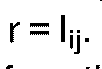


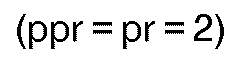
- At step S7 the first predicted value "pr" will be 2 as shown in Fig. 3. In this case, because pr=2 and r=1 at step S8, the program proceeds to step S9 and "ppr" (the first predicted value of a run) is set at two (
value 0 is stored as the run length at step S10. Next, at step S11 for obtaining "pr", 1 is set as a predicted value as shown in Fig. 3. In this case, because pr=1, ppr=2 and rr=3, it is discriminated at step S12 that pr ≠ ppr and pr ≠ rr, so that the program proceeds to step S13. Because pr=1 and r=1, "pr" is discriminated to be equal to "r" at step S13 and the program proceeds to step S14. - Now, steps S14, S15 and S4 are repeated till "j" becomes "a+b" and "ℓ" becomes "b" at step S14. When


- Steps S14, S15 and S4 are again repeated till "j" becomes (a+b+c) and "ℓ" becomes c (
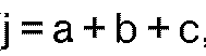


run type 0. Then, at step S6, "rr", "r" and "ℓ" are respectively set at zero, one and zero (rr=0, r=1, ℓ=0). Because pr=1 is obtained this time as shown in Fig. 3 at step S7, the program proceeds to S14 via S8. - Steps S14, S15 and S4 are again repeated till "j" becomes (a+b+c+d) and ℓ becomes d (


run type 1. Then, at step S6, "rr", "r" and "ℓ" are respectively set at one, zero and zero (rr=1, r=0, ℓ=0). Because a value predicted at step S7 at this time is two (pr=2), the program proceeds to step S8. Because pr=2 and r=0 in this case, "pr" is discriminated not to be equal to "r" at step S8, and the program proceeds to step S9. After "pr" (pr=2) is substituted into "ppr" (
value 0 is stored as the run length at step S10. - The program returns to step S11 again, wherein the
value 2 is presented as "pr". However because pr=2, ppr=2 and rr=1, and therefore
value 1 is obtained. However, because pr=1, ppr=2 and rr=1, and therefore
- Steps S14, S15 and S4 are again repeated till "j" becomes (a+b+c+d+e) and "ℓ " becomes "e". When


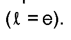
- Referring next to Fig. 7, after "j" is set at zero (


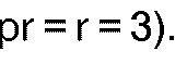


value 2 of "pr" is used for "ppr" (
value 1 is obtained as "pr" (pr=1) at step S8, the program proceeds to step S10 via step S9 because pr=1, ppr=2, rr=3 and therefore pr≠ppr and pr≠rr. The run length "b" which is not zero is obtained at step S10. Because "ℓ" is not zero (ℓ≠0), the program proceeds to step S12, at which "rr" is replaced with pr to be one (
- pr=0 is obtained this time at step S4. In this case,

value 0 of "pr" (
- Similarly, the program proceeds to step S4 and 1 is obtained as a predicted value (pr=1) at this step. In this case, the run length ℓ obtained at step S5 is "d" which is not zero (

value 1 of "pr" (
- The program again returns to step S4 via step S16. At this time a predicted value obtained at step S4 is two (pr=2) and the run length ℓ obtained at step S5 is zero (ℓ=0). Therefore the program proceeds from step S6 to step S7, at which the
value 2 of "pr" is set as the value of "ppr" (
value 0 is set as the run length ℓ of therun type 3. The next prediction result at step S8 is two (pr=2). In this case, however, because


- An example of the present invention has been described above in reference with Fig. 6 and Fig. 7. In the above description, only one method has been presented as a method for predicting the run types. However, other methods will be available.
- For example, in the case that an appropriate preprocessing is not applied to a character image, so that a character portion and/or a white background contains pixels having values identical to those of pixels contained in an edge portion, or in the case that not only character images but also natural images are desired to be treated, the run type is not necessarily changed in the
order - As will be understood from Fig. 9, according to the prediction rule, three values closest to a value representing the preceding run type are nominated as the first, second and third predicted values. For example, when the preceding run type is 0, the
value 1 is first nominated as the first predicted value. Thevalues value 1 in this increasing order. When the preceding run type is 3, thevalue 2 is first nominated as the first predicted value. Thevalues value 3 in this decreasing order. When the preceding run type "rr" is 1 or 2, there are two possible values as the closest one. For example, when the preceding run type "rr" is 1, the closest values are 2 and 0. In this case, priority is decided in consideration of the run type before the preceding run type. If the run type before the preceding run type "rrr" is 0, priority is given to thevalue 2 over thevalue 0, considering that values of run types being processed may be increasing. On the other hand, if the run type "rrr" before the precedingrun type 1 is 3 or 2, priority is given to thevalue 0 over thevalue 2, considering that values of run types being processed may be decreasing. - In any case, when the first predicted value does not coincide with an actual run type, the two other values are provided one by one in accordance with priority as the second and third predicted values.
- The above description has been made in reference with a two-bit character image. The present invention, however, can be applied to a reversible coding for any n-bit images. In this case, the number of run types to be predicted will be 2n.
Claims (7)
- An image data compression method to be employed in coding digital image data whose pixels are represented by n bits and which include 2n different types of runs, wherein while a run length (ℓ) of a current run is counted, a value representing a run type of the current run is predicted, said prediction is repeated till a predicted value (pr) coincides with an actual value (r) of the run type of said current run; when a predicted value (pr) does not coincide with the actual value (r) of the run type of said current run, a run length for an imaginary run having the predicted value (pr) is regarded as zero and said run length of the imaginary run is entropy coded; on the other hand, when a predicted value (pr) coincides with an actual value (r), the actual run length of the current run is entropy coded.
- The method as claimed in Claim 1, wherein a run type of only a headmost run in each of lines of the image data is obtained without being predicted and n-bit data representing the run type of each headmost run are added to the run length data entropy coded of runs following the headmost run.
- The method as claimed in Claim 2, wherein a specific formula is prepared in advance so that predicted values are obtained in a predetermined order in consideration of a run type of each headmost run.
- The method as claimed in Claim 3, wherein in the case that two or more predictions are done to a current run, a same predicted value is not repeatedly obtained and a value representing an actual type of an immediately previous run is not used as a predicted value for said current run.
- The method as claimed in Claim 3, wherein when the digital image data are two-bit image data, the predicted values are obtained in the order of 1, 2, 3, 2, 1, 0, although an initial predicted value for runs in each line of the image data is decided based on a run type of a headmost run of each line.
- The method as claimed in Claim 1, wherein predicted values for a current run are tabulated relative to a preceding run and a run before the preceding run.
- The method as claimed in Claim 6, wherein a specific number of values which are closest to a value representing a run type of a preceding run are selected as predicted values.
Applications Claiming Priority (2)
| Application Number | Priority Date | Filing Date | Title |
|---|---|---|---|
| JP329316/89 | 1989-12-19 | ||
| JP1329316A JP2511158B2 (en) | 1989-12-19 | 1989-12-19 | Image compression device |
Publications (2)
| Publication Number | Publication Date |
|---|---|
| EP0434005A1 EP0434005A1 (en) | 1991-06-26 |
| EP0434005B1 true EP0434005B1 (en) | 1994-06-08 |
Family
ID=18220103
Family Applications (1)
| Application Number | Title | Priority Date | Filing Date |
|---|---|---|---|
| EP90124644A Expired - Lifetime EP0434005B1 (en) | 1989-12-19 | 1990-12-18 | Image data compression method using a run prediction technique |
Country Status (4)
| Country | Link |
|---|---|
| US (1) | US5091977A (en) |
| EP (1) | EP0434005B1 (en) |
| JP (1) | JP2511158B2 (en) |
| DE (1) | DE69009713T2 (en) |
Families Citing this family (9)
| Publication number | Priority date | Publication date | Assignee | Title |
|---|---|---|---|---|
| JP3327650B2 (en) * | 1993-04-15 | 2002-09-24 | キヤノン株式会社 | Recording device |
| JP3106021B2 (en) * | 1992-11-30 | 2000-11-06 | キヤノン株式会社 | Pattern data compression method and apparatus and output method and apparatus |
| AU695626B2 (en) * | 1995-02-03 | 1998-08-20 | Koninklijke Philips Electronics N.V. | Video image colour encoding |
| JP3364074B2 (en) * | 1995-06-05 | 2003-01-08 | 株式会社リコー | Bit plane coding device |
| US6055273A (en) * | 1996-09-02 | 2000-04-25 | Seiko Epson Corporation | Data encoding and decoding method and device of a multiple-valued information source |
| US6094453A (en) * | 1996-10-11 | 2000-07-25 | Digital Accelerator Corporation | Digital data compression with quad-tree coding of header file |
| US7212677B2 (en) * | 2000-01-11 | 2007-05-01 | Minolta Co., Ltd. | Coder, coding method, program, and image forming apparatus for improving image data compression ratio |
| US7424163B1 (en) | 2004-07-13 | 2008-09-09 | Itt Manufacturing Enterprises, Inc. | System and method for lossless image compression |
| DE102007020292A1 (en) * | 2007-04-30 | 2008-11-13 | Siemens Ag | Method for compressing data using run-length coding, in particular for medical image data |
Family Cites Families (7)
| Publication number | Priority date | Publication date | Assignee | Title |
|---|---|---|---|---|
| JPS5816665B2 (en) * | 1975-10-30 | 1983-04-01 | ケイディディ株式会社 | Fuakushimirishingounofugoukahoushiki |
| US4344086A (en) * | 1979-11-20 | 1982-08-10 | Nippon Electric Co., Ltd. | Encoder for encoding a multilevel pel signal sequence with probability representative mode codes allotted to prediction error codes for each pel signal and a decoder therefor |
| JPS56128070A (en) * | 1980-03-13 | 1981-10-07 | Fuji Photo Film Co Ltd | Band compressing equipment of variable density picture |
| US4360840A (en) * | 1980-05-13 | 1982-11-23 | Am International, Inc. | Real time data compression/decompression scheme for facsimile transmission system |
| JPS57164662A (en) * | 1981-04-03 | 1982-10-09 | Hitachi Ltd | Compression system for multilevel signal |
| US4701803A (en) * | 1984-06-05 | 1987-10-20 | Canon Kabushiki Kaisha | Image data compression apparatus |
| US4725885A (en) * | 1986-12-22 | 1988-02-16 | International Business Machines Corporation | Adaptive graylevel image compression system |
-
1989
- 1989-12-19 JP JP1329316A patent/JP2511158B2/en not_active Expired - Fee Related
-
1990
- 1990-12-18 DE DE69009713T patent/DE69009713T2/en not_active Expired - Fee Related
- 1990-12-18 EP EP90124644A patent/EP0434005B1/en not_active Expired - Lifetime
- 1990-12-19 US US07/630,200 patent/US5091977A/en not_active Expired - Fee Related
Also Published As
| Publication number | Publication date |
|---|---|
| DE69009713T2 (en) | 1995-01-12 |
| JPH03188768A (en) | 1991-08-16 |
| EP0434005A1 (en) | 1991-06-26 |
| JP2511158B2 (en) | 1996-06-26 |
| DE69009713D1 (en) | 1994-07-14 |
| US5091977A (en) | 1992-02-25 |
Similar Documents
| Publication | Publication Date | Title |
|---|---|---|
| EP0130415B1 (en) | Data compression for graphics images | |
| EP1014699B1 (en) | Method of selecting colors for pixels within blocks for block truncation encoding | |
| US5297220A (en) | Image processing system for image compression and decompression | |
| US4628534A (en) | Method for changing the resolution of compressed image data | |
| EP0098958B1 (en) | Method of encoding and transmitting documents for text processing systems | |
| US5267052A (en) | Encoding the original image data and progessively encoding the image data independently | |
| CA2197329C (en) | Encoding method and system, and decoding method and system | |
| EP0412047A1 (en) | Method and system for arithmetic coding and decoding | |
| JPS6118381B2 (en) | ||
| EP0415513A2 (en) | Image reduction system | |
| US5271072A (en) | Image reduction of binary images using filtering processing | |
| EP0434005B1 (en) | Image data compression method using a run prediction technique | |
| EP0295024A2 (en) | Method and apparatus for decompressing encoded data | |
| EP0105085B1 (en) | A method and apparatus for filtering grey scale image data | |
| US4893187A (en) | Image processing apparatus | |
| EP0902398B1 (en) | Method and system for compressing and decompressing binary representations of dithered images | |
| US5406282A (en) | Data coding and decoding with improved efficiency | |
| EP0741489A1 (en) | Image encoding/decoding method | |
| EP0309167A2 (en) | Method of decoding image data in run representation | |
| Algazi et al. | Compression of binary facsimile images by preprocessing and color shrinking | |
| US4703516A (en) | Character image data compression system | |
| JP3095071B2 (en) | Pattern matching encoding apparatus and encoding method therefor | |
| US20030076998A1 (en) | Methods and apparatus for data compression | |
| JPH05151349A (en) | Image data compression method and encoding circuit | |
| US6553144B1 (en) | Coding method and coding apparatus for bi-level document image |
Legal Events
| Date | Code | Title | Description |
|---|---|---|---|
| PUAI | Public reference made under article 153(3) epc to a published international application that has entered the european phase |
Free format text: ORIGINAL CODE: 0009012 |
|
| 17P | Request for examination filed |
Effective date: 19901218 |
|
| AK | Designated contracting states |
Kind code of ref document: A1 Designated state(s): DE FR GB |
|
| 17Q | First examination report despatched |
Effective date: 19930817 |
|
| GRAA | (expected) grant |
Free format text: ORIGINAL CODE: 0009210 |
|
| AK | Designated contracting states |
Kind code of ref document: B1 Designated state(s): DE FR GB |
|
| REF | Corresponds to: |
Ref document number: 69009713 Country of ref document: DE Date of ref document: 19940714 |
|
| ET | Fr: translation filed | ||
| PLBE | No opposition filed within time limit |
Free format text: ORIGINAL CODE: 0009261 |
|
| STAA | Information on the status of an ep patent application or granted ep patent |
Free format text: STATUS: NO OPPOSITION FILED WITHIN TIME LIMIT |
|
| 26N | No opposition filed | ||
| PGFP | Annual fee paid to national office [announced via postgrant information from national office to epo] |
Ref country code: DE Payment date: 20001211 Year of fee payment: 11 |
|
| PGFP | Annual fee paid to national office [announced via postgrant information from national office to epo] |
Ref country code: FR Payment date: 20001212 Year of fee payment: 11 |
|
| PGFP | Annual fee paid to national office [announced via postgrant information from national office to epo] |
Ref country code: GB Payment date: 20001213 Year of fee payment: 11 |
|
| PG25 | Lapsed in a contracting state [announced via postgrant information from national office to epo] |
Ref country code: GB Free format text: LAPSE BECAUSE OF NON-PAYMENT OF DUE FEES Effective date: 20011218 |
|
| REG | Reference to a national code |
Ref country code: GB Ref legal event code: IF02 |
|
| PG25 | Lapsed in a contracting state [announced via postgrant information from national office to epo] |
Ref country code: DE Free format text: LAPSE BECAUSE OF NON-PAYMENT OF DUE FEES Effective date: 20020702 |
|
| GBPC | Gb: european patent ceased through non-payment of renewal fee |
Effective date: 20011218 |
|
| PG25 | Lapsed in a contracting state [announced via postgrant information from national office to epo] |
Ref country code: FR Free format text: LAPSE BECAUSE OF NON-PAYMENT OF DUE FEES Effective date: 20020830 |
|
| REG | Reference to a national code |
Ref country code: FR Ref legal event code: ST |