EP0434006A2 - Dispositif musical automatique - Google Patents
Dispositif musical automatique Download PDFInfo
- Publication number
- EP0434006A2 EP0434006A2 EP90124645A EP90124645A EP0434006A2 EP 0434006 A2 EP0434006 A2 EP 0434006A2 EP 90124645 A EP90124645 A EP 90124645A EP 90124645 A EP90124645 A EP 90124645A EP 0434006 A2 EP0434006 A2 EP 0434006A2
- Authority
- EP
- European Patent Office
- Prior art keywords
- auto
- play
- data
- playing
- memory
- Prior art date
- Legal status (The legal status is an assumption and is not a legal conclusion. Google has not performed a legal analysis and makes no representation as to the accuracy of the status listed.)
- Granted
Links
- 230000001360 synchronised effect Effects 0.000 claims description 28
- 238000001514 detection method Methods 0.000 claims description 10
- 238000000034 method Methods 0.000 description 83
- 230000000994 depressogenic effect Effects 0.000 description 48
- 230000000881 depressing effect Effects 0.000 description 15
- 230000003287 optical effect Effects 0.000 description 14
- 238000010586 diagram Methods 0.000 description 12
- 230000003252 repetitive effect Effects 0.000 description 10
- 230000000694 effects Effects 0.000 description 5
- 230000006870 function Effects 0.000 description 5
- 230000005236 sound signal Effects 0.000 description 2
- 125000004122 cyclic group Chemical group 0.000 description 1
- 238000005192 partition Methods 0.000 description 1
- 238000005070 sampling Methods 0.000 description 1
- 239000004065 semiconductor Substances 0.000 description 1
Images


Classifications
-
- G—PHYSICS
- G10—MUSICAL INSTRUMENTS; ACOUSTICS
- G10H—ELECTROPHONIC MUSICAL INSTRUMENTS; INSTRUMENTS IN WHICH THE TONES ARE GENERATED BY ELECTROMECHANICAL MEANS OR ELECTRONIC GENERATORS, OR IN WHICH THE TONES ARE SYNTHESISED FROM A DATA STORE
- G10H1/00—Details of electrophonic musical instruments
- G10H1/18—Selecting circuits
- G10H1/26—Selecting circuits for automatically producing a series of tones
-
- G—PHYSICS
- G10—MUSICAL INSTRUMENTS; ACOUSTICS
- G10H—ELECTROPHONIC MUSICAL INSTRUMENTS; INSTRUMENTS IN WHICH THE TONES ARE GENERATED BY ELECTROMECHANICAL MEANS OR ELECTRONIC GENERATORS, OR IN WHICH THE TONES ARE SYNTHESISED FROM A DATA STORE
- G10H1/00—Details of electrophonic musical instruments
- G10H1/36—Accompaniment arrangements
- G10H1/361—Recording/reproducing of accompaniment for use with an external source, e.g. karaoke systems
- G10H1/363—Recording/reproducing of accompaniment for use with an external source, e.g. karaoke systems using optical disks, e.g. CD, CD-ROM, to store accompaniment information in digital form
-
- G—PHYSICS
- G10—MUSICAL INSTRUMENTS; ACOUSTICS
- G10H—ELECTROPHONIC MUSICAL INSTRUMENTS; INSTRUMENTS IN WHICH THE TONES ARE GENERATED BY ELECTROMECHANICAL MEANS OR ELECTRONIC GENERATORS, OR IN WHICH THE TONES ARE SYNTHESISED FROM A DATA STORE
- G10H2220/00—Input/output interfacing specifically adapted for electrophonic musical tools or instruments
- G10H2220/005—Non-interactive screen display of musical or status data
- G10H2220/011—Lyrics displays, e.g. for karaoke applications
Definitions
- the present invention relates to an auto-playing apparatus which uses a recording medium having audio data recorded thereon and memory means storing auto-play data to ensure reproduction of the audio data in synchronism with auto-playing based on the auto-play data.
- Auto-playing apparatuses for use in an electronic musical instrument store pitch data and tone length data, corresponding to each note of a piece of music, into a semiconductor memory according to the progress of the music, reads out these data from the memory and send them to a tone generator to automatically play the music as memorized.
- Such auto-playing apparatuses have been proposed and many electronic musical instruments available on the market today have such a function.
- the technique of an auto-playing apparatus of this type is disclosed in detail in, for example, USP 4,624,171 by Yuzawa et al.
- the auto-playing apparatuses are very effective in learning how to play a music with an electronic musical instrument, because the player or user can objectively judge one's own musical performance by executing auto-playing based on key operating signals, which have been produced by the performance and stored as auto-play data in the memory.
- a music generally consists of a plurality of musical parts that are to be played by a plurality of instruments.
- the learning effect would be further improved if a music including the entire musical parts is played on the background when playing a specific musical part. Playing a melody part while listening a music being played on the background makes it easier for one to grasp the timing for the melody part that the user should play.
- the music which should be played on the background can easily be reproduced by playing an analog record, compact disk (CD) or the like by means of a player. Particularly, it is more effective to use a record or CD on which such a music has been recorded in minus-one format.
- the minus-one type record or CD is manufactured particularly for those who are learning how to play a piano and has a piano concerto without the piano part recorded thereon, for example. The user therefore plays his own musical instrument while reproducing the music recorded in the minus-one format.
- the learning effect would be enhanced by using the aforementioned auto-playing apparatus to auto-play the music data recorded on the record, CD or the like.
- This auto-playing requires that the minus-one type record, CD or the like be played first and the auto-playing apparatus be started at the proper timing for the musical part which the user should play.
- an auto-playing apparatus comprises a recording medium having audio data recorded thereon; reproducing means, coupled to the recording medium, for reproducing the audio data therefrom; detection means, coupled to the reproducing means, for detecting position data about a present play position on the recording medium which is being played; memory means for storing auto-play data and position data of that audio data on the recording medium which is to be reproduced in synchronism with the auto-play data, in association with the auto-play data; auto-playing means, coupled to the memory means, for reading the auto-play data from the memory means and sequentially generating corresponding tone signals to execute auto-playing; instruction means for instructing an operation concerning the auto-playing, the instruction means specifying at least a start point of a synchronized reproduction to perform data reproduction from the recording medium in synchronism with reproduction of the auto-play data; and control means, coupled to the instruction means, the auto-playing means, the detection means and the reproducing means, for executing data reproduction from the recording medium from a
- the data reproduction from the recording medium can surely be synchronized with the reproduction of the auto-play data for an auto-playing operation even from any part. Therefore, the timing to start a melody in the whole piece of music and the image of the entire music piece can easily be grasped, producing an effect of a teaching machine which can ensure synchronized reproduction of only a specific part.
- Fig. 1 is a block circuit diagram illustrating the general structure of an auto-playing apparatus (1)
- Fig. 2 is a detailed diagram of a CD drive section (102);
- Fig. 3 is a detailed diagram of an instrument operating section (202);
- Fig. 4 is a detailed diagram of a timer circuit (209)
- Fig. 5 is a diagram showing the frame format of a compact disc (105);
- Fig. 6 is a diagram illustrating the format of a subcoding frame of the compact disc (105);
- Fig. 7 is a diagram illustrating the content of a control bit Q in a lead-in area on the compact disc (105);
- Fig. 8 is a diagram showing the content of a control bit Q in a program area on the compact disc (105);
- Fig. 9 is a diagram showing the recorded contents of the compact disc (105).
- Fig. 10 is a diagram showing how data is stored in an auto-play memory (208);
- Fig. 11 is a flowchart illustrating a control operation in sequencer write mode
- Figs. 12A to 12D are flowcharts illustrating control operations in sequencer priority mode and CD priority mode
- Figs. 13A to 13E are flowcharts illustrating a control operation in sequencer priority repeat mode
- Figs. 14A to 14F are flowcharts illustrating a control operation in CD priority repeat mode.
- Fig. 15 is a flowchart illustrating a control operation in a synchronous adjustment process.
- Fig. 1 is a block diagram illustrating the general circuit arrangement of an auto-playing apparatus 1 according to one embodiment of the present invention, which is provided with an electronic keyboard instrument and a CD player.
- a block 100 surrounded by a one-dot chain line is a CD player section and a block 200 also surrounded by a one-dot chain line is an electronic keyboard instrument section.
- a CD 105 is set in a holder section (not shown) of the CD player section 100.
- the CD player section 100 can play CDs available on the market.
- suitable CDs in this embodiment are those on which music pieces are recorded in minus-one format.
- the minus-one type CDs are those on which audio data, such as a piano concerto excluding the piano part, for example, is recorded.
- a TOC (Table of Contents) memory 101 stores TOC data of a lead-in area which is to be read out when the CD 105 is set on the CD player section 100.
- the TOC data will be described later.
- Reference numeral "102" denotes a CD drive section whose structure is illustrated in Fig. 2.
- a PLAY switch 1021 is used to instruct ordinary playing of a CD and CD playing in CD priority mode (to be described later).
- a STOP switch 1022 serves to instruct to stop playing a CD.
- a PAUSE switch 1023 serves to specify the point where playing a CD starts, in CD priority mode.
- An FF (Feed Forward) switch 102 an REW (Rewind) switch 1025 are used to move the point where playing a CD starts, in CD priority mode.
- Numerical keys 1026, "0" to "9,” are used to designate a music number to play a CD.
- a CD controller 103 may be a microprocessor which performs the general control of the CD player section 100.
- the CD controller 103 exchanges various types of data between a subcode signal processor 110, an instrument controller 201 and the TOC memory 101.
- the CD controller 103 sends a drive control signal to a servo controller 104.
- the servo controller 104 controls the number of rotations of a disc motor 106 that drives the CD 105, so as to make constant the linear velocity of the tracks on the CD 105.
- the servo controller 104 also executes the focus servo and tracking servo of an optical pickup 107 which irradiates a laser beam on the tracks on the CD 105.
- the focus servo is to detect a focus error from the status of reflection light of the laser beam and control the driving of an objective lens in the optical pickup 107 in the direction of the optical axis based on the focus error.
- the tracking servo is to control the laser beam from the optical pickup 107 to be accurately focused onto the center of a target track on the CD 105 by causing a pickup motor to move the optical pickup 107 in the radial direction of the CD 105 or permitting the internal lens of the pickup 107 to trace the tracks while detecting a deviation of the laser beam from the center of the target track on the CD 105.
- Upheavals called pits are formed on that face of the CD 105 where the laser beam is to be irradiated, and PCM (Pulse Code Modulation) signals are recorded by the pits.
- the optical pickup 107 detects the presence/absence of pits based on the amount of reflected light of the irradiated laser beam and sends an electric signal corresponding to the presence/absence and the length of the pits to a demodulator 109.
- the demodulator 108 detects a frame sync signal from the electric signal from the optical pickup 107 to discriminate the partition between symbol words, and subjects an EFM (Eight to Fourteen Modulation) modulated 14-bit symbol word in each frame to EFM demodulation to convert it to the original 8-bit symbol word.
- EFM Eight to Fourteen Modulation
- one containing audio data is sent to an audio data signal processor 109 and one containing a subcode is sent to the aforementioned subcode signal processor 110.
- the former signal processor 109 writes input audio data into a RAM (Random Access Memory) 116, and performs an error correction based on a Reed-Solomon code as well as a de-interleaving process to restore 16-bit digital audio data frame by frame.
- the digital audio data is sent to a D/A (Digital to Analog) converter 112.
- the D/A converter 112 converts the received digital audio data into an analog audio signal, which is sent to an amplifier 114 via an LPF (Low-pass Filter) 111 having a cutoff frequency, a half of the sampling frequency.
- LPF Low-pass Filter
- the subcode signal processor 110 performs an error detection, error correction and de-interleaving process on an 8-bit subcode to restore the subcode.
- 8-bit subcode two control bits P and Q are output to the CD controller 103; the control bits P and Q will be described in detail later.
- the instrument operating section 202 has a keyboard 202 1 , and other keys including a mode select switch 202 2 , START switch 202 3 , STOP switch 202 4 , UP switch 202 5 , DOWN switch 202 6 , A switch 202 7 , B switch 202 8 and numeric keys 202 9 . These switches will be described later.
- An instrument controller 201 which many be a microprocessor, controls an operation to write auto-play data in sequencer write mode (to be described later) and an auto-play operation in sequencer priority mode or CD priority mode (both modes will be described later) in addition to the ordinary play operation (normal mode).
- a tone generator 203 produces a musical tone signal based on play data from the instrument controller 201. This musical tone signal is sent to a D/A converter 204.
- the musical tone signal from the tone generator 203 is converted into an analog musical tone signal by the D/A converter 204 and an LPF (Low-pass filter) 205.
- the converted output is released to the outside via an amplifier 206 and a loudspeaker 207.
- a timer circuit 209 which is used to control the operation associated with auto-playing, has the structure shown in Fig. 4. The structure and the operation of the timer circuit 209 will be depicted later.
- a display section 210 displays key data D KY at the point of starting auto-playing in sequencer priority mode as will be described later.
- the recording format of digital data on the CD 105 will be described below.
- digital data is recorded in a unit called frame in which a sync pattern (synchronize pattern) 301 consisting of 24 channel bits, a subcode 302 for one symbol, audio data 303 for 12 symbols, a parity word 304 for 4 symbols, audio data 305 for 12 symbols and a parity word 306 for 4 symbols are arranged in the named order.
- a sync pattern synchronize pattern
- one symbol in Fig. 5 consists of 8-bit data at a stage before EFM modulation.
- Audio data to be recorded on the CD 105 is digital data of which each sample is sampled at 44.1 kHz and quantized by 16 bits. Therefore, each sample is expressed by two symbols.
- audio data 303 and 305 for 24 symbols in total are recorded in one frame in Fig. 5, audio data for 12 samples is recorded in one frame.
- the parity words 304 and 306 are called a CIRC (Cross Interleave Reed-Solomon Code).
- Fig. 6 shows a data format around a subcode 302.
- the individual bits of each 8-bit subcode 302 per frame are called P, Q, R, S, T, U, V and W, respectively.
- 8-bit subcodes for 98 frames are grouped as one subcoding frame, and 8-bit subcodes of the 0-th frame and first frame of the 98 frames are sync patterns for the subcoding frame.
- the subcode signal processor 110 shown in Fig. 1 uses these subcoding-frame recognition sync patterns to recognize the subcodes P through W of each of the second to 97-th frames.
- the bits R to W are user's bits which are used at the time of recording data such as a still picture. As these bits are not used in the present invention, their description will be omitted.
- control bits Q in the TOC information for one piece of music will be described below.
- Q1, Q2, ..., and Q96 respectively correspond to the control bits Q of the second frame to the 97-th frame in Fig. 6.
- Q1 through Q4 are a flag which is used to discriminate the number of channels of audio data and presence/absence of emphasis.
- the next four bits, Q5 to Q8, are "0001" and the subsequent eight bits, Q9 to Q16, are all "0.”
- the next eight bits, Q17 to Q24, are a point representing data of a track number (music number).
- the next three eight bits represent the absolute times each expressed in terms of minutes, seconds and frame number, which will be described later; these are data, which increase till the end of the lead-in area with the beginning of this area as 0, are used by the internal system and are not particularly indicated outside.
- the next eight bits, Q49 to Q56, are all "0," and the subsequent three 8-bit groups represent the absolute times each expressed in terms of minutes, seconds and frame number.
- These three time data represent the starting point of each piece of music in a program area, which corresponds to the aforementioned point * music number), as the time elapsed from the starting point of the program area. For instance, with a CD having three pieces of music recorded thereon as shown in Fig. 9, the absolute time data from the starting points of these pieces of music are recorded for points 01, 02 and 03, respectively.
- the last sixteen bits are an error detection code (CRCC: Cyclic Redundancy Check Code).
- CRCC Cyclic Redundancy Check Code
- the CRCC one type of error detection code, is the remainder of data bits divided by a given number; the remainder is used as check bits.
- control bit P is data indicating an interval between pieces of music and inside a piece of music; the bit is set to 1 when the associated frame corresponds to the interval between pieces of music and audio data 303 and 305 (see Fig. 3) are not present, and is set to 0 when the frame corresponds to a point inside a piece of music and the audio data are present.
- time data shown in Fig. 8 are recorded using the control bits Q.
- the subcodes since 98 frames (time for one frame is 136.05 ⁇ sec) are treated as one subcoding frame, as described referring to Fig. 6, it is possible to record the time for one subcoding frame (136.05 ⁇ sec x 98), i.e., time data in the units of 1/75 second, using the control bits Q.
- the first and second four bits are the same as those of the control bits Q of the TOC data described referring to Fig. 7.
- the next eight bits indicate a track number (music number), and the following eight bits are an index which represents the details of the track number.
- the next three 8-bit sets represent absolute times indicating the times elapsed from the starting point of each piece of music expressed in terms of minutes, seconds and frame number, and the indication is updated every 1/75 second.
- the next eight bits are all "0.”
- the subsequent three 8-bit sets represent absolute times indicating the times elapsed till the point of the subcoding frame from the starting point of the program area with the accuracy of 1/75 second, as in the case of the TOC data described referring to Fig. 7.
- the last sixteen bits are an error detection code (CRCC).
- the subcodes for 98 frames constitute one subcoding frame which corresponds to 1/75 second, as explained earlier referring to Fig. 4, so that a sequence of data for 75 subcoding frames is the same second data.
- subcoding frames in the same second data are given sequential subcoding frame numbers, from 0 to 74, which have been called the frame numbers for short in the foregoing description.
- the absolute time data from the starting point of each piece of music corresponding to each music number can be detected in the unit of one subcoding frame, i.e., with the accuracy of 1/75 second.
- the CD controller 103 reads out the TOC data to accurately access to the starting point of audio data of an arbitrary piece of music.
- autoplay data will be sometimes expressed as sequence data, but both are the same.
- a user can cause the CD player section 100 to function as an ordinary CD player using the individual switches 102 1 -102 6 of the CD drive section 102 shown in Fig. 2.
- the mode select switch 202 2 on the instrument operating section 202 shown in Fig. 3 is operated to select the normal mode, the user can use the electronic keyboard instrument section 200 as an ordinary electronic keyboard instrument.
- the user can perform the auto-playing operation with the electronic keyboard instrument section 200 in synchronism with the operation of the CD player section 100 to reproduce each piece of music on the CD 105.
- the user operate the mode select switch 202 2 to select the sequencer write mode.
- the user can store auto-play data into an auto-play memory 208 using the keyboard 202 1 of the instrument operating section 202 in accordance with a piece of music to be plated by the CD player section 100.
- the instrument controller 201 receives CD absolute time data at that time from the CD controller 103 and stores the data together with play data associated with the key-ON into the auto-play memory 208.
- the user can perform the following operation by operating the mode select switch 202 2 of the instrument operating section 202 to select the sequencer priority mode, one of sequencer play modes.
- the user can arbitrarily select the timing of the auto-play data stored in the auto-play memory 208 at which auto-playing should start while viewing what is displayed on the display section 210 by operating the UP switch 202 5 and DOWN switch 202 6 of the instrument operating section 202.
- the START switch 2023 of the instrument operating section 202 to start the auto-playing at the selected timing, reproduction of a piece of music starts at the timing corresponding to the audio data on the CD 105 in synchronism with the start of the auto-playing.
- This control is executed by the instrument controller 201 using the CD absolute time data stored together with a key-ON command in the auto-play memory 208. It is possible to execute the auto-playing operation without playing the CD 105.
- the user can perform the following operation by operating the mode select switch 202 2 of the instrument operating section 202 to select the CD priority mode, one of the sequencer play modes.
- the user can arbitrarily select the timing to start auto-playing while reproducing the audio data recorded on the CD 105 by operating the FF switch 102 4 or REW switch 102 5 (Fig. 2) of the CD drive section 102.
- the user depresses the PAUSE switch 102 3 of the CD drive section 102 to temporarily stop reproducing the audio data, then depresses the START switch 202 3 (Fig. 3) of the instrument operating section 202.
- This operation can restart the reproduction of the audio data which has been in the paused state and can start auto-playing at the timing corresponding to the associated play contents in the auto-play memory 208 in synchronism with the restart of the data reproduction.
- this control is also carried out by the instrument controller 201 using the CD absolute time data stored together with the key-ON command in the auto-play memory 208.
- the user can also perform the following operation by operating the mode select switch 202 2 of the instrument operating section 202 to select the sequencer priority repeat mode, one of the sequencer play modes.
- the user can select the timing of the auto-play data stored in the auto-play memory 208 at which auto-play should start while viewing what is displayed on the display section 210 by operating the UP switch 202 5 and DOWN switch 202 6 (Fig. 3) of the instrument operating section 202.
- the content of the selection can be secured by operating the A switch 202 7 (Fig. 3).
- the user can likewise select the timing to end the auto-playing, and can secure the selected content by the operation of the B switch 202 8 (Fig. 3).
- the user can also determine the repeat number to indicate how many times the playing range should be repeated, using the numerical keys 2029 (Fig. 3).
- the START switch 202 3 (Fig. 3) of the instrument operating section 202 to start the auto-playing at the selected timing secured by the A switch 202 7
- reproduction of a piece of music can be started at the timing corresponding to the audio data on the CD 105 in synchronism with the start of the auto-playing and the synchronized playing can continue to the timing secured by the B switch 202 8 .
- This control is executed using the CD absolute time data stored together with a key-ON command in the auto-play memory 208.
- the synchronized playing can be repeated by the number of times specified by using the numeric keys 202 9 .
- the user can perform the following operation by operating the mode select switch 202 2 of the instrument operating section 202 to select the CD priority repeat mode, one of the sequencer play modes.
- the user can arbitrarily select the timing to synchronously start auto-playing while reproducing the audio data recorded on the CD 105 by depressing the PAUSE switch 1023 (Fig. 2) after the operation of the FF switch 102 4 or REW switch 1025 of the CD drive section 102.
- the content of the selection can be secured by operating the A switch 2027 (Fig. 3).
- the reproduction of the audio data starts again from the paused point of time, whereby the user can select the timing to end the auto-playing of the electronic keyboard instrument section 200 in synchronism as done in the case of selecting the starting point.
- the selected content can be determined by the operation of the B switch 202 8 (Fig. 3). As in the sequencer priority repeat mode, the user can also determine the repeat number, using the numerical keys 202 9 .
- the START switch 202 3 (Fig. 3) of the instrument operating section 202 reproduction of the audio data starts at the timing determined by the A switch 202 7 and the auto-playing can start from the corresponding timing of the associated content of the play in the auto-play memory 208 in synchronism with the start of the reproduction of the audio data.
- the synchronized playing can continue to the timing secured by the B switch 202 8 and this operation can be repeated by the number of specified times.
- This control is also executed using the CD absolute time data stored together with a key-ON command in the auto-play memory 208, as has been done in sequencer priority repeat mode.
- sequencer write mode sequencer priority mode
- CD priority mode sequencer priority repeat mode
- CD priority repeat mode CD priority repeat mode
- Fig. 11 is an operational flowchart illustrating the operation in this mode, while Fig. 10 illustrates the data structure in the auto-play memory 208. The following description will be given referring to these diagrams.
- the user selects the sequencer write mode by operating the mode select switch 202 2 (Fig. 3) of the instrument operating section 202.
- the user performs the following operation. More specifically, the user operates the numerical keys 102 6 of the CD drive section 102 to select and specify the music number of the CD 105 which is wanted to be reproduced in synchronism with the auto-playing, then depresses the PLAY switch 102 1 .
- the CD controller 100 in the CD player section 100 accesses the TOC memory 101 to read out music number data associated with the number specified by the numerical keys 102 6 and CD absolute time data.
- the CD controller 103 controls the optical pickup 107 through the servo controller 104 to move the pickup 107 to the position on the CD 105 corresponding to the CD absolute time data.
- the CD controller 103 outputs the CD absolute time data read from the TOC memory 101 to the instrument controller 201. In this state, reproduction of the audio data has not been conducted yet.
- the CD controller 103 starts the operational flowchart shown in Fig. 11.
- step S701 it is determined in step S701 whether or not the START switch 202 3 of the instrument operating section 202 has been depressed.
- step S702 If the START switch 202 3 has been depressed, it is then determined in step S702 whether or not the PLAY switch 102 1 of the CD drive section 102 has been depressed in advance.
- step S702 If the user has depressed in advance the PLAY switch 1021 to play a piece of music on the CD 105 in synchronism with the auto-playing, the decision in step S702 becomes YES and the flow advances to step S703.
- a CD top setting command C TP is written at a memory address 1 in the auto-play memory 208 as shown in Fig. 10.
- CD absolute time data D AT indicating the top of the piece of music on the CD 105, which is to be reproduced in synchronism with the auto-playing and has been sent from the CD controller 103 in advance, is likewise written at a memory address 2, as shown in Fig. 10.
- CD play command C PY is written at a memory address 3 as shown in Fig. 10.
- step S704 a CD play instruction is given to the CD controller 103.
- the CD controller 103 in the CD player section 100 drives the disk motor 106 through the servo controller 104. Consequently, the audio data of the music piece which has already been selected and whose top has been set by the user is read out from the CD 105 via the optical pickup 107, demodulator 109 and audio data signal processor 111, and is then sent from the D/A converter 112 to the loudspeaker 115 through the LPF 113 and amplifier 114. The amplified data is released from the loudspeaker 115.
- the user plays the keyboard 202 1 of the instrument operating section 202 in accordance with a piece of music reproduced in this manner from the CD 105. Accordingly, every time the process of step S705 in the repetitive operational sequence from S705, to S706, to S707 and back to S705, play data input from the keyboard 202 1 is sequentially written as sequence data in the auto-play memory 208 as shown in Fig. 10.
- the sequence data includes a wait command C WT and wait data D WT , key-ON command C ON and key data D KY , key-OFF command C OF and key data D KY , CD absolute time data D AT , etc. as shown in Fig. 10.
- the wait command C WT serves to hold the execution of next play data for a time specified by the wait data D WT , which is generated by the timer circuit 209 shown in Fig. 4. Every time a playing operation is executed, a reset signal RST is input via an OR circuit 209 5 (Fig. 4) to a timer counter 209 2 from the instrument controller 201, resetting this counter. Thereafter, the timer counter 209 2 performs its count-up operation according to a clock from a reference clock generator 209 1 .
- the instrument controller 201 fetches the count output of the timer counter 209 2 as the wait data D WT at the time the next play data is received, then writes the wait data D WT into the auto-play memory 208 and resets the timer counter 209 2 using the reset signal RST.
- the wait command C WT and wait data D WT at a memory address 4 in Fig. 10 indicate the time to the first key operation after depression of the START switch 202 3 of the instrument operating section 202 by the user.
- the key-ON command C ON serves to instruct the start of generation of a musical tone with the pitch specified by the key data D KY .
- the key-OFF command C OF serves to instruct to stop the generation of a musical tone with the pitch specified by the key data D KY .
- the CD controller 103 receives the CD absolute time data D AT from the CD 105 detected at that time from the CD controller 103, and writes it at the memory address next to that of the key data D KY following the key-ON command C ON . In this manner, the timing of a music piece reproduced by the CD player section 100 at the time of each key-ON operation is recorded in the auto-play memory 208.
- step S707 When the user depresses the STOP switch 202 4 (see Fig. 3) of the instrument operating section 202, this event is detected in step S707, and an end command C E is written in the auto-play memory 208 as shown in Fig. 10 in step S708, terminating the sequencer write mode.
- the PLAY switch 102 1 has not been depressed in advance and the decision in S702 becomes NO.
- the CD top setting command C TP the CD absolute time data D AT indicating the top of the music piece and the CD play command C PY will not be written in the auto-play memory 208, nor is a play instruction given to the CD player section 100.
- the flow then jumps to step S705 where the sequence data is written in the auto-play memory 208.
- writing the CD absolute time data D AT into the auto-play memory 208 for each key-ON command C ON will not be done. This operation corresponds to writing of auto-play data in the conventional electronic musical instrument having an auto-playing function.
- the instrument controller 201 in Fig. 1 executes the operational flowchart shown in Figs. 12A and 12B, and the decision in step S801 (Fig. 12A) becomes YES.
- the user arbitrarily selects the timing of the content of the play data stored in the auto-play memory 208 as shown in Fig. 10 at which auto-play should start, using the UP switch 202 5 and DOWN switch 202 6 (Fig. 3) of the instrument operating section 202 and the display section 210.
- This operation is realized as follows under the control of the instrument controller 201.
- step S802 it is determined whether or not the UP switch 202 5 of the instrument operating section 202 has been depressed.
- step S802 When the UP switch 202 5 has been depressed, the decision in S802 becomes YES and the memory address on the auto-play memory 208 is incremented by an address counter (not particularly shown) to advance to the address where the next key-ON command C ON is stored. In other words, the memory address in the auto-play memory 208 is incremented by "1" in step S803 and this address increment is repeated until the key-ON command C ON is detected in step S804.
- step S804 When the key-ON command C ON is detected, the decision in S804 becomes YES, the present memory address is incremented by "+1" in step S809 and the key data D KY stored at the memory address in the auto-play memory 208 next to where the key-ON command C ON is stored is read out. This key data D KY is then displayed on the display section 210 shown in Fig. 1, thus permitting the user to confirm the presently-specified key data D KY in the auto-play memory 208.
- step S810 the memory address is further incremented by "+1" in step S810, and it is determined in step S811 whether or not the CD absolute time data D AT exists at that memory address. If the user performs an operation to write the sequence data into the auto-play memory 208 with the PLAY switch 102 1 depressed in advance in order to play a piece of music, recorded on the CD 105, in synchronism with the auto-playing, the CD absolute time data D AT is stored in the auto-play memory 208 at the next address to the address of the key data D KY following each key-ON command C ON as shown in Fig. 10. In this case, therefore, the decision in S811 becomes YES.
- the CD absolute time data D AT corresponding to the wait data D WT presently displayed on the display section 210 is read out from the auto-play memory 208 and is transferred to the CD controller 103 in step S812. Meanwhile, the instrument controller 201 gives an instruction to set the CD top to the CD controller 103.
- the CD controller 103 in turn controls the optical pickup 107 through the servo controller 104 to set the top position on the CD 105 corresponding to the aforementioned CD absolute time data D AT .
- step S811 If the user performs an operation to write the sequence data into the auto-play memory 208 without depressing the PLAY switch 102 1 in advance because there is no need to play a piece of music, recorded on the CD 105, in synchronism with the auto-playing in the aforementioned sequencer write mode, the CD absolute time data D AT is not stored in the auto-play memory 208. In this case, therefore, the decision in S811 becomes NO. In this case, since it is unnecessary to play a music piece on the CD 105 at the time of auto-playing, no instruction to set the CD top will be given in step S812.
- step S813 it is determined whether or not the START switch 202 3 (Fig. 3) of the instrument operating section 202 has been depressed; if this switch has been depressed, the flow returns to S802.
- step S802 If it is judged in the aforementioned step S802 that the UP switch 202 5 (Fig. 3) of the instrument operating section 202 has not been depressed, i.e., if the decision is NO, the flow advances to S805 where it is determined whether or not the DOWN switch 202 6 (Fig. 3) of the instrument operating section 202 has been depressed.
- step S805 When the DOWN switch 202 6 has been depressed, the decision in S805 becomes YES and the memory address on the auto-play memory 208 is decremented by an address counter (not particularly shown) to return to the memory address where the previous key-ON command C ON is stored.
- the memory address in the auto-play memory 208 is decremented by "1" in step S807 and this address decrement is repeated until the key-ON command C ON is detected in step S808.
- the memory address is decremented to "0,” no further decrement is executed and the flow jumps to step S813.
- the decision in S808 becomes YES, and thereafter, the operational sequence from S809 to S813 is executed to display the decremented memory address, set the top of a music piece on the CD 105 and detect the depression of the START switch 202 3 , as in the aforementioned case where the UP switch 2025 is depressed.
- the memory address on the auto-play memory 208 is incremented or decremented in the above manner so that the start point of the auto-play can be moved to the position desired by the user.
- a value acquired by decrementing the present memory address by "3" is saved in a buffer (not particularly shown) in the instrument controller 201.
- the content of the present memory address indicates the memory address where the CD absolute time data D AT next to the key data D KY following the key-ON command C ON is stored in the aforementioned process of S804 to S810. Therefore, the content of the buffer acquired by decrementing this value by "3" indicates one memory address previous to the position of the key-ON command C ON specified by the user. The meaning of this will be described later.
- the content of the memory address is set to "1" in S816, and it is determined in S817 whether or not the CD top setting command C TP exists in the memory address "1."
- the CD top setting command C TP is stored at the memory address "1" in the auto-play memory 208 as shown in Fig. 10.
- the decision in S817 becomes YES.
- an instruction to play a piece of music recorded on the CD 105 is given to the CD controller 103 in S818.
- the play start timing in this case is the point where the CD top setting has been done in the aforementioned step S812.
- the address data saved in the buffer in S815 is set again at the memory address in S819.
- This content indicates one memory address precious to the position of the key-ON command C ON specified by the user, as described earlier. This process is to give matching with the process of S843 (to be described later).
- the CD top setting command C TP is not stored in the auto-play memory 208 (see step S702 in Fig. 11). In this case, therefore, the decision in S817 becomes NO. In this case, it is unnecessary to play a piece of music recorded on the CD 105 at the auto-playing time, so that no CD play instruction in S818 will be given.
- the decision in S814 becomes YES and the flow advances to S820.
- the user depresses the START switch 202 3 without depressing the UP switch 2025 or DOWN switch 2026 at all after operating the mode select switch 2022 of the instrument operating section 202 to select the sequencer priority mode, or where the user depresses the UP switch 2025 several times, then depresses the DOWN switch 2026 the same number of times so that the decision in S806 becomes YES.
- the present memory address is incremented by "1" in S820, and it is then determined in S821 whether or not the CD top setting command C TP exists at the memory address. Since the present memory address is "0,” the content of the memory address when incremented by "1" becomes “1.”
- the CD top setting command C TP is stored at the memory address "1" in the auto-play memory 208 as shown in Fig. 10.
- the decision in S821 becomes YES. Accordingly, the content of the memory address is further incremented by "1" to be "2" in S822.
- the CD top setting command C TP is not stored in the auto-play memory 208 (see step S702 in Fig. 11). In this case, therefore, the decision in S821 becomes NO. In this case, it is unnecessary to play a piece of music recorded on the CD 105 at the auto-playing time, so that the CD top setting command in S822 and the CD play instruction in S823 will not be given. In this case, the content of the memory address is set again in S824.
- the content of the memory address indicates one memory address previous to the top memory address "1" where the sequence data concerning the play data is stored. This is the result of the user specifying the top of a music piece as the timing to start the auto-playing. This relation is the same as in the case of the aforementioned S819.
- the sequence data is read out from each memory address while the memory address of the auto-play memory 208 is sequentially incremented from the memory address set in S819, S823 or S824, and the auto-playing operation is executed in accordance with the content of the sequence data.
- the address increment in this case is executed on the basis of the operation of the timer circuit 209 which will be described later.
- the instrument controller 201 when the instrument controller 201 reads out the key-ON command C ON from the memory address "6" in Fig. 10, it further reads out the next key data D KY and instructs the tone generator 203 to start generating a musical tone with the pitch corresponding to the key data.
- the instrument controller 201 When the instrument controller 201 reads out the key-OFF command C OF from the memory address "11" in Fig. 10, it then reads out the next key data D KY and instructs the tone generator 203 to stop generating the presently-generated musical tone with the pitch corresponding to the key data.
- the increment of the memory address is realized as follows. That is, when the instrument controller 201 reads out the wait command C WT from the memory address "9" in Fig. 10, it further reads out the wait data D WT and sets the data in a wait register 2093 in the timer circuit 209 shown in Fig. 4. Meanwhile, the timer counter 2092 in the timer circuit 209 is reset at the previous timing of incrementing the memory address, as described later. Thereafter, the timer counter 2092 in Fig. 4 is sequentially counted up in accordance with the clock from the reference clock generator 2091. The output of the timer counter 2092 is compares with the wait data D WT set in the wait register 2093 by a comparator 2094.
- the comparator 2094 When they coincide with each other, the comparator 2094 outputs a signal indicating the coincidence as an address increment signal INC.
- This signal INC is sent to the instrument controller 201 which in turn increments the memory address in the auto-play memory 208 from which data is to be read out.
- the address increment signal INC resets the wait register 2093 as well as the timer counter 2092 through the OR circuit 2095 to be ready for a process to the next wait data D WT .
- the above auto-playing operation will be terminated when the sequence data at every memory address up to the last memory address in the auto-play memory 208 is read out during the auto-playing, or when the end command C E is read out from the auto-play memory 208 during the auto-playing, or when the user depresses the STOP switch 2024 of the instrument operating section 202, and when such an event is detected in S844, S845 or S846.
- the instrument controller 201 in Fig. 1 executes the operational flowchart shown in Fig. 12A, and the decision in step S801 (Fig. 12A) becomes YES and the flow advances to S825 in Fig. 12C.
- step S826 it is determined whether or not the CD top setting command C TP is stored at the memory address "1." If the user performs an operation to write the sequence data into the auto-play memory 208 with the PLAY switch 1021 depressed in advance in order to play a piece of music, recorded on the CD 105, in synchronism with the auto-playing, the CD top setting command C TP is stored in the auto-play memory 208 at the memory address "1" as shown in Fig. 10. In this case, therefore, the decision in S826 becomes YES.
- the CD top setting command C TP is not stored at the memory address "1" in the auto-play memory 208. In this case, therefore, the decision in S826 becomes NO. In this case, since it is unnecessary to play a music piece on the CD 105 at the time of auto-playing and it is insignificant to set the CD priority mode, the process will be terminated without executing anything.
- step S828 the CD absolute time data D AT from the top of the piece of music to be reproduced from the CD 105 in the auto-playing is read out from the memory address "2" and is transferred to the CD controller 103. Meanwhile, the instrument controller 201 gives an instruction to set the CD top to the CD controller 103. The CD controller 103 in turn controls the optical pickup 107 through the servo controller 104 to set the top position on the CD 105 corresponding to the aforementioned CD absolute time data D AT .
- step S829 the content of the memory address is incremented by "1" to be "3.” Based on the CD play command C PY stored at the memory address "3,” a CD play instruction is given to the CD controller 103. As a result, the CD player section 100 starts playing the CD 105 from the top of the piece of music whose top has been set in S828.
- the user can arbitrarily select the timing to synchronously start the auto-playing of the electronic keyboard instrument section 200 while reproducing the audio data recorded on the CD 105 by operating the FF switch 1024 and REW switch 1025 (Fig. 2) of the CD drive section 102.
- the instrument controller 201 determines through the CD controller 103 in S830 whether the PAUSE switch 1023 (Fig. 2) of the CD drive section 102 has been depressed. When the user has depressed the PAUSE switch 1023, the reproduction of the audio data is paused under the control of the CD controller 103.
- the instrument controller 201 receives the CD absolute time data D AT at the pause time from the CD controller 103, and holds it in a latch circuit (not particularly shown).
- the CD absolute time data D AT corresponding to the detected key-ON command C ON is read out from that memory address and it is determined whether or not this data exceeds (or is greater than) the aforementioned, latched CD absolute time data at the pause time. If the former data does not exceed the latter, it means that the memory address in the auto-play memory 208 has not reached the position corresponding to the timing at the pause time. The flow then returns to S832 and the process sequence of S832 to S835 is repeated to retrieve the next key-ON command C ON on the auto-play memory 208.
- step S8308 the detected CD absolute time data D AT is held in the aforementioned latch circuit. Since what has been previously held in the latch circuit becomes unnecessary, it is deleted.
- the present memory address is decremented by "3."
- This memory address indicates the address where the first CD absolute time data D AT which has exceeded the CD absolute time data at the pause time is stored through the process of S836, e.g., at the address "8" in Fig. 10. Therefore, the memory address after decremented by "3" indicates one address previous to the address like the address "5" in Fig. 10 where the key-ON command C ON corresponding to the CD absolute time data D AT is stored.
- This process is done to provide the matching with the process of S843 which will be described later. This relation is the same as the case of the aforementioned step S819.
- the decision in S840 becomes YES and an instruction to play a piece of music on the CD 105 is given to the CD controller 103 in the subsequent step S841.
- the instrument controller 201 receives the CD absolute time data sequentially detected from the CD 105 through the subcode signal processor 110 by the CD controller 103, and determines whether or not the received data equals the aforementioned content of the latch circuit.
- the latch circuit is holding the first CD absolute time data D AT on the auto-play memory 208 which has exceeded the CD absolute time data at the pause time.
- Reproduction of the audio data in the paused state can start and the auto-playing can start from the corresponding timing of the associated play content on the auto-play memory 208 in synchronism with the start of the reproduction, in the above manner.
- the instrument controller 201 in Fig. 1 executes the operational flowchart shown in Figs. 13A and 13E.
- the user arbitrarily selects the timing of the content of the play data stored in the auto-play memory 208 as shown in Fig. 10 at which auto-play should start, using the UP switch 2025 and DOWN switch 2026 (Fig. 3) of the instrument operating section 202 and the display section 210.
- This operation is realized as the processes of S901 to S914 in Fig. 13A.
- step S901 it is determined whether or not the UP switch 2025 of the instrument operating section 202 has been depressed.
- step S901 When the UP switch 2025 has been depressed, the decision in S901 becomes YES and the memory address on the auto-play memory 208 is incremented by an address counter (not particularly shown) to advance to the address where the next key-ON command C ON is stored. In other words, the memory address in the auto-play memory 208 is incremented by "1" in step S902 and this address increment is repeated until the key-ON command C ON is detected in step S903.
- step S903 When the key-ON command C ON is detected, the decision in S903 becomes YES, the present memory address is incremented by "+1" in step S908 and the key data D KY stored at the memory address in the auto-play memory 208 next to where the key-ON command C ON is stored is read out. This key data D KY is then displayed on the display section 210 shown in Fig. 1, thus permitting the user to confirm the presently-specified key data D KY in the auto-play memory 208.
- step S910 it is determined in step S910 whether or not the CD absolute time data D AT exists at that memory address. If the user performs an operation to write the sequence data into the auto-play memory 208 with the PLAY switch 1021 depressed in advance in order to play a piece of music, recorded on the CD 105, in synchronism with the auto-playing, the CD absolute time data D AT is stored in the auto-play memory 208 at the next address to the address of the key data D KY following each key-ON command C ON as shown in Fig. 10. In this case, therefore, the decision in S910 becomes YES.
- the CD absolute time data D AT corresponding to the wait data D WT presently displayed on the display section 210 is read out from the auto-play memory 208 and is transferred to the CD controller 103 in step S911.
- the instrument controller 201 gives an instruction to set the CD top to the CD controller 103.
- the CD controller 103 in turn controls the optical pickup 107 through the servo controller 104 to set the top position on the CD 105 corresponding to the aforementioned CD absolute time data D AT .
- a value acquired by decrementing the present memory address by "3" is held in a buffer (not particularly shown) in the instrument operating section 201 in S912.
- the content of the present memory address indicates the memory address where the CD absolute time data D AT next to the key data D KY following the key-ON command C ON is stored in the aforementioned steps S903-S909. Therefore, the content of the buffer acquired by decrementing this value by "3" indicates one memory address previous to the position of the key-ON command C ON specified by the user. This meaning will be described later.
- step S913 it is determined whether or not the A switch 202 7 (Fig. 3) of the instrument operating section 202 has been depressed; if this switch has been depressed, the flow returns to S901.
- step S901 If it is judged in the aforementioned step S901 that the UP switch 2025 (Fig. 3) of the instrument operating section 202 has not been depressed, i.e., if the decision is NO, the flow advances to S904 where it is determined whether or not the DOWN switch 2026 (Fig. 3) of the instrument operating section 202 has been depressed.
- step S904 When the DOWN switch 2026 has been depressed, the decision in S904 becomes YES and the memory address on the auto-play memory 208 is decremented by an address counter (not particularly shown) to return to the memory address where the previous key-ON command C ON is stored.
- the memory address in the auto-play memory 208 is dencremented by "1" in step S906 and this address decrement is repeated until the key-ON command C ON is detected in step S907.
- the memory address is decremented to "0,” no further decrement is executed and the flow jumps to step S913.
- the decision in S907 becomes YES, and thereafter, the operational sequence from S908 to S911 is executed to display the decremented memory address, store the CD absolute time data D AT into the repeat memory Al, decrement the memory address by "3" and detect the depression of the A switch 2027, as in the aforementioned case where the UP switch 2025 is depressed.
- the memory address on the auto-play memory 208 is incremented or decremented in the above manner so that the start point of the auto-play can be moved to the position desired by the user.
- the content of the present memory address is stored in a repeat memory A2 (not particularly shown) in the instrument operating section 201.
- the content of the present memory address indicates one memory address previous to the position of the key-ON command C ON on the auto-play memory 208 specified by the user in the aforementioned step S912. As a result, the memory address at the start of the auto-playing is determined.
- the user can arbitrarily select the auto-playing stop timing of the auto-play data stored in the auto-play memory 208 as shown in Fig. 10, in the same manner as done in the operation to specify the start of the auto-playing.
- This process is realized as the process sequence of s915 to S929 shown in Fig. 13B.
- the user operates the UP switch 2025 or DOWN switch 2026 (Fig. 3) of the instrument operating section 202 to increment or decrement the memory address while searching for the key-ON command C ON on the auto-play memory 208.
- This process is executed as the process sequence of S915-S921. These processes are almost the same as those of S901-S907 in the operation to specify the start of the auto-playing.
- the flow jumps to S925 where an error message "Input error. Set again" is displayed, then the processing from S915 is repeated. This is because that the memory address cannot become "0" as the start of the auto-playing has already been specified.
- the process of S922 is executed. That is, it is determined whether or not the content of the changed memory address exceeds the content of the repeat memory A2 incremented by "1." Since the content of the repeat memory A2 indicates one memory address previous to the position of the key-ON command C O N on the auto-play memory 208 at the start of the auto-playing specified by the user as described above, this memory content incremented by "1" is the memory address where the key-ON command C ON on the auto-play memory 208 at the start of the auto-playing specified by the user is stored. Since the memory address specified as the end of the auto-playing cannot exceed the memory address specified as the start of the auto-playing, the error message is displayed in S925 if the decision in S922 becomes NO, and the processing from S915 will be repeated.
- step S924 it is determined whether or not the B switch 202 8 (Fig. 3) of the instrument operating section 202 has been depressed. If this switch has not been depressed, the flow returns to S915.
- the present memory address is decremented by "1" in S927.
- the present memory address indicates the memory address (see Fig. 10) where the key data D KY is stored through the aforementioned step S923
- the present memory address when decremented by "1" becomes the memory address, specified as the end of the auto-playing, in the auto-play memory 208 where the key-ON command C ON is stored.
- the content of the present memory address is stored in a repeat memory B (not particularly shown) in the instrument operating section 201 shown in Fig. 1.
- the content of the present memory address indicates the memory address in the auto-play memory 208 specified by the user in the aforementioned step S927. As a result, the memory address at the end of the auto-playing is determined.
- the user specifies the start and the end of the auto-playing, then specifies the repeat number to repeat the auto-playing in that range.
- This process is realized as the processes of S930 and S931 shown in Fig. 13C.
- register data corresponding to the depressed key is stored in a repeat memory C (not shown) in the instrument controller 201 in S931.
- the user depresses the START switch 2023 (Fig. 3) of the instrument operating section 202 to execute the auto-playing operation by the electronic keyboard instrument section 200 and the synchronized reproduction by the CD player section 100.
- the decision in S932 becomes YES, then the content of the repeat memory A2 or the value of one memory address previous to the position of the key-ON command C ON in the auto-play memory 208 at the start of the auto-playing specified by the user is set at the memory address in step S933 shown in Fig. 13D.
- the content of the memory address is incremented by "3" and the resultant memory content indicates the address in the auto-play memory 208 where the CD absolute time data D AT associated with the key-ON command C ON at the start of the auto-playing is stored (see Fig. 10).
- S936 it is determined whether or not the CD absolute time data D AT exists at that memory address. If the user performs an operation to write the sequence data into the auto-play memory 208 with the PLAY switch 1021 depressed in advance in order to play a piece of music, recorded on the CD 105, in synchronism with the auto-playing, the CD absolute time data D AT is stored in the auto-play memory 208 at the next address to the address of the key data D KY following each key-ON command C ON as shown in Fig. 10. In this case, therefore, the decision in S936 becomes YES.
- the CD absolute time data D AT associated with the key-ON command C ON in the auto-play memory 208 at the start of the auto-playing is read out from the above memory address and is transferred to the CD controller 103.
- the instrument controller 201 gives an instruction to set the CD top to the CD controller 103.
- the CD controller 103 in turn controls the optical pickup 107 through the servo controller 104 to set the top position on the CD 105 corresponding to the aforementioned CD absolute time data D AT .
- step S938 an instruction to play a piece of a music recorded on the CD 105 is given to the CD controller 103.
- the timing to play the music piece is synchronized with the start of the auto-playing specified by the user in the above manner.
- the content of the repeat memory A2 is set again at the memory address in S939.
- the memory content indicates one memory address previous to the position of the key-ON command C ON in the auto-play memory 208 at the start of the auto-playing specified by the user.
- the specifying the memory address previous by one is to provide the matching with the process of step S946 which will be described later.
- the CD top setting command C TP is not stored in the auto-play memory 208 (see S702 in Fig. 11). In this case, therefore, the decision in S936 becomes NO. In this case, since it is unnecessary to play a music piece on the CD 105 at the time of auto-playing, the CD play instruction or the like in steps S937 and S938 will not be executed.
- the decision in S934 becomes YES and the flow advances to S940.
- The is a case where the user depresses the A switch 2027 without depressing the UP switch 2025 or DOWN switch 2026 at all after operating the mode select switch 2022 of the instrument operating section 202 to select the sequencer priority repeat mode, or where the user depresses the UP switch 2025 several times, then depresses the DOWN switch 2026 the same number of times so that the decision in S905 becomes YES.
- the present memory address is incremented by "1" in S940, and it is then determined in S941 whether or not the CD top setting command C TP exists at the memory address. Since the present memory address is "0,” the content of the memory address when incremented by "1" becomes “1.”
- the CD top setting command C TP is stored at the memory address "1" in the auto-play memory 208 as shown in Fig. 10.
- the decision in S941 becomes YES. Accordingly, the content of the memory address is further incremented by "1" to be "2" in S942.
- the CD top setting command C TP is not stored in the auto-play memory 208 (see step S702 in Fig. 11). In this case, therefore, the decision in S941 becomes NO. In this case, it is unnecessary to play a piece of music recorded on the CD 105 at the auto-playing time, so that the CD top setting command in S943 and the CD play instruction in S942 will not be given. In this case, the content of the memory address is set again in S945.
- the content of the memory address indicates one memory address previous to the top memory address "1" where the sequence data concerning the play data is stored. This is the result of the user specifying the top of a music piece as the timing to start the auto-playing. This relation is the same as in the case of the aforementioned S939.
- the sequence data is read out from each memory address while the memory address of the auto-play memory 208 is sequentially incremented from the memory address set in S939, S944 or S945, and the auto-playing operation is executed in accordance with the content of the sequence data.
- the address increment in this case is executed on the basis of the operation of the timer circuit 209.
- the instrument controller 201 when the instrument controller 201 reads out the key-ON command C ON from the memory address "6" in Fig. 10, it further reads out the next key data D KY and instructs the tone generator 203 to start generating a musical tone with the pitch corresponding to the key data.
- the instrument controller 201 When the instrument controller 201 reads out the key-OFF command C OF from the memory address "11" in Fig. 10, it then reads out the next key data D KY and instructs the tone generator 203 to stop generating the presently-generated musical tone with the pitch corresponding to the key data.
- the increment of the memory address is realized as follows. That is, when the instrument controller 201 reads out the wait command C WT from the memory address "9" in Fig. 10, it further reads out the wait data D WT and sets the data in a wait register 2093 in the timer circuit 209 shown in Fig. 4. Meanwhile, the timer counter 2092 in the timer circuit 209 is reset at the previous timing of incrementing the memory address, as described later. Thereafter, the timer counter 2092 in Fig. 4 is sequentially counted up in accordance with the clock from the reference clock generator 2091. The output of the timer counter 2092 is compares with the wait data D WT set in the wait register 2093 by a comparator 2094.
- the comparator 2094 When they coincide with each other, the comparator 2094 outputs a signal indicating the coincidence as an address increment signal INC.
- This signal INC is sent to the instrument controller 201 which in turn increments the memory address in the auto-play memory 208 from which data is to be read out.
- the address increment signal INC resets the wait register 2093 as well as the timer counter 2092 through the OR circuit 2095 to be ready for a process to the next wait data D WT .
- the above-described operation for a single auto-playing is terminated as the memory address for the sequence data exceeds the content of the repeat memory B, causing the decision in S947 to be YES. That is, since the content of the repeat memory B indicates the memory address where the key-ON command C ON in the auto-play memory 208 at the end of the auto-playing specified by the user is stored, the first auto-playing will be terminated after executing the commands up to this key-ON command C ON in S946.
- the content of the repeat memory C is decremented by "1" in S948.
- the memory content is decremented by "1" every time the single auto-playing is terminated.
- next step S950 it is determined whether or not the content of the repeat memory C becomes "0."
- the content of the repeat memory C is decremented by "1" in S948 every time the single auto-playing is terminated. If the memory content is not "0,” the decision in S950 becomes NO and the flow returns to S933 (Fig. 13D). As a result, the operation for the synchronized auto-playing is repeated as described above.
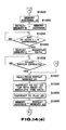
- the instrument controller 201 in Fig. 1 executes the operational flowchart shown in Figs. 14A to 14F.
- step S1002 it is determined whether or not the CD top setting command C TP is stored at the memory address "1." If the user performs an operation to write the sequence data into the auto-play memory 208 with the PLAY switch 1021 depressed in advance in order to play a piece of music, recorded on the CD 105, in synchronism with the auto-playing, the CD top setting command C TP is stored in the auto-play memory 208 at the memory address "1" as shown in Fig. 10. In this case, therefore, the decision in S1002 becomes YES.
- the CD top setting command C TP is not stored at the memory address "1" in the auto-play memory 208. In this case, therefore, the decision in S1002 becomes NO. In this case, since it is unnecessary to play a music piece on the CD 105 at the time of auto-playing and it is insignificant to set the CD priority repeat mode, the process will be terminated without executing anything.
- step S1004 the CD absolute time data D AT from the top of the piece of music to be reproduced from the CD 105 in the auto-playing is read out from the memory address "2" and is transferred to the CD controller 103. Meanwhile, the instrument controller 201 gives an instruction to set the CD top to the CD controller 103. The CD controller 103 in turn controls the optical pickup 107 through the servo controller 104 to set the top position on the CD 105 corresponding to the aforementioned CD absolute time data D AT .
- next step S1005 the content of the memory address is incremented by "1" to be "3.” Based on the CD play command C PY stored at the memory address "3,” a CD play instruction is given to the CD controller 103. As a result, the CD player section 100 starts playing the CD 105 from the top of the piece of music whose top has been set in S1004.
- the user can arbitrarily select the timing to synchronously start the auto-playing of the electronic keyboard instrument section 200 (this timing will be hereinafter simply called “play start timing") while reproducing the audio data recorded on the CD 105 by depressing the PAUSE switch 1023 (Fig. 2) after the operation of the FF switch 1024 or REW switch 1025 of the CD drive section 102.
- the instrument controller 201 determines through the CD controller 103 in S1006 whether the PAUSE switch 1023 (Fig. 2) of the CD drive section 102 has been depressed. When the user has depressed the PAUSE switch 1023, the reproduction of the audio data is paused under the control of the CD controller 103.
- the decision in the next step S1007 becomes YES. Accordingly, the play start timing specified by the user is set through the above operation.
- the instrument controller 201 receives the CD absolute time data D AT at the pause time from the CD controller 103, and holds it in the latch circuit (not particularly shown).
- the CD absolute time data D AT corresponding to the detected key-ON command C ON is read out from that memory address and it is determined whether or not this data exceeds (or is greater than) the aforementioned, latched CD absolute time data at the pause time. If the former data does not exceed the latter, it means that the memory address in the auto-play memory 208 has not reached the position corresponding to the timing at the pause time. The flow then returns to S1009 and the process sequence of S1009 to S1012 is repeated to search for the next key-ON command C ON on the auto-play memory 208.
- the detected CD absolute time data D AT is stored in the repeat memory Al (not particularly shown) in the instrument controller 201.
- the present memory address is decremented by "3."
- This memory address indicates the address where the first CD absolute time data D AT which has exceeded the CD absolute time data at the pause time at the play start timing is stored through the process of S1015, e.g., at the address "8" in Fig. 10. Therefore, the memory address after decremented by "3" indicates one address previous to the address like the address "5" in Fig. 10 where the key-ON command C ON corresponding to the CD absolute time data D AT is stored.
- This process is done to provide the matching with the process of S1041 which will be described later. This relation is the same as the case of the aforementioned step S912.
- the content of this memory address is stored in the repeat memory A2 in the next step S1019. Accordingly, the memory address for the play start timing is set.
- an instruction to play a piece of music on the CD 105 is given to the CD controller 103 to reproduce the audio data again but from the paused point in S1020.
- the user can therefore select the timing to end the playing of a music piece recorded on the CD 105 (this timing will be hereinafter called “play end timing"), in synchronism with the auto-playing of the electronic keyboard instrument section 200, in the same manner as done in the case of selecting the play start point.
- This process is realized by the processing of S1021-S1033, which is almost the same as the processing of S1006-S1019 in the case where the user specifies the play start timing.
- the process of S1025 is executed to increment the content of the memory address by "1.” That is, the content of the memory address is incremented by "2" through the processes of S1025 and S1026.
- the content of the memory address indicates one memory address previous to where the key-ON command C ON at the play start timing specified by the user is stored (see S1018).
- the content of the memory address becomes an address next to where the key-ON command C ON at the mentioned play start timing is stored (see the description of S1018). This prevents the same key-ON command C ON as the one at the play start timing from being detected in S1027. This may occur when the user instantaneously depresses the PAUSE switch 1023 after the playing of the music piece on the CD 105 is restarted in S1020.
- the process corresponding to S1017 is not executed after the execution of the process of S1031 corresponding to the S1016.
- the memory address indicates the address where the first CD absolute time data D AT which has exceeded the CD absolute time data at the pause time at the play end timing is stored.
- the memory address when incremented by "2" therefore becomes the address where the key-ON command C ON corresponding to the CD absolute time data D AT is stored.
- the content of the memory address is stored in the repeat memory B (not shown) in the instrument operating section 201 in S1033.
- the content of the memory address indicates the address where the first CD absolute time data D AT which has exceeded the CD absolute time data at the pause time at the play end timing specified by the user is stored. Accordingly, the memory address at the play end timing is set.
- the user After specifying the play start timing and play end timing, the user specifies the repeat number to repeat the auto-playing in the range in the above manner.
- This process is realized by the processes in S1034 and S1035 shown in Fig. 14E, and this is the same as the processes in S930 and S931 in the aforementioned sequencer priority repeat mode. Accordingly, the repeat number for the auto-playing is set in the repeat memory C (not shown) in the instrument operating section 201.
- the user depresses the START switch 2023 (Fig. 3) of the instrument operating section 202 to execute the synchronized reproduction by the CD player section 100 and the auto-playing operation of the electronic keyboard instrument section 200 in synchronism with the reproduction.
- the decision in S1036 becomes YES, and the content of the repeat memory Al is read out in S1037.
- This content is the CD absolute time data D AT (see S1017) read out from the auto-play memory 208 corresponding to the play start timing.
- the CD absolute time data D AT is sent to the CD controller 103 and the CD top setting command is given to the CD controller 103. This sets the top of a music piece on the CD 105 corresponding to the aforementioned CD absolute time data D AT on the side of the CD player section 100.
- an instruction to play the music piece on the CD 105 is given to the CD controller 103 in S1039.
- the play start timing is synchronized with the play start timing specified by the user as described above.
- the timing is not strictly the same as the play start timing on the CD 105 specified by the user, but the difference hardly causes a different in hearing.
- the content of the repeat memory A2 is set at the memory address in S1040.
- the content indicates one memory address previous to the position of the key-ON command C ON in the auto-play memory 208 at the play start point specified by the user.
- the memory address of the auto-play memory 208 is sequentially incremented from the memory address set in S1040, and the sequence data is read out from each memory address.
- the auto-playing is performed in accordance with the content of the sequence data.
- the above-described single auto-playing is terminated when the memory address of the sequence data exceeds the value of the repeat memory B and the decision in S1042 becomes YES.
- the content of the repeat memory B indicates the address where the key-ON command C ON corresponding to the first CD absolute time data D AT which has exceeded the CD absolute time data at the pause time at the play end timing is stored.
- the CD controller 103 and instrument controller 201 independently execute the playing of the music piece of the CD 105 and the auto-playing based on the sequence data stored in the auto-play memory 208 until the auto-playing is terminated at the point specified by the user.
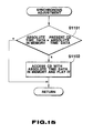
- Fig. 15 illustrates an operational flowchart for the synchronous adjusting process for the correction. This process is executed by the instrument controller 201.
- the instrument controller 201 executes the synchronous adjusting operation illustrated in Fig. 15 every time one key-ON command C ON is read out from the auto-play memory 208 or the key-ON command C ON is read out several times (five times).
- the key-ON command C ON is read out from the auto-play memory 208 first, then the memory address is incremented by "2" and the corresponding CD absolute time data D AT is read out (see Fig. 10).
- the instrument controller 201 receives the CD absolute time data from the CD 105 which is sequentially detected via the subcode signal processor 110 by the CD controller 103. These two CD absolute time data are then compared with each other.
- the instrument controller 201 accesses to the CD controller 103 using the CD absolute time data D AT read out from the auto-play memory 208, and instructs to play a music piece at that timing.
- the auto-playing operation by the electronic keyboard instrument section 200 can always be synchronized with the operation to play the music piece by the CD player section 100.
- CD absolute time data D AT is stored in the auto-play memory 208 at the timing to store the key-ON command C ON in sequencer write mode.
- a command such as a program change (timbre change)
- the CD absolute time data D AT may be stored at the timing when this command is stored. This can permits the auto-playing to be synchronized with the CD reproduction at the timing of the program change.
- the CD absolute time data D AT may be stored at timings of various types of sequence data. Further, a CD music number and CD relative time data may be used in place of the CD absolute time data D AT .
- sequencer priority mode it is possible to repress the UP switch 2025 or DOWN switch 2026 to jump to an arbitrary timing during the playing of a CD in synchronism with the auto-playing so that the synchronized reproduction is restarted from the jumped timing.
- the UP switch 2025 or DOWN switch 2026 is depressed during the process of S843 shown in Fig. 12B, an interrupt process is performed.
- the auto-playing and the CD playing are temporarily stopped at that timing.
- the processes of steps including and following S802 in Fig. 12A have only to be executed. This way can cope with the case where there is a part which the user does not want to listen and can be fast-forwarded, or where there is a part which the user wants to listen repeatedly so that this part is rewound.
- sequence data may be stored in advance in user's bits (recording area of a CD-ROM) of subcodes on a ROM or CD, these sequence data may be transferred to the auto-play memory 208 at the time of auto-playing.
- the form, type or the like of the sequence data to be stored may be arbitrarily altered in accordance with instruments which perform the auto-playing.
- the repeating operation may be done within a range from the top of a music piece to an arbitrarily set point or from an arbitrarily set point to the end of the music piece. Further, it is possible to repeat a specific refrain part specified by the user after the auto-playing is carried out while fully playing a certain piece of music.
- Various types of repeat patterns may be set, and they may be selected by a program.
- the auto-playing by the electronic keyboard instrument section 200 is executed in synchronism with the playing of a piece of music on the CD 105 by the CD player section 100.
- This invention is not however limited to CD players, but may be applied to any music playing apparatus as long as it can sequentially output time data in accordance with the playing of the music piece, such as a DAT (Digital Audio Tape Recorder). Further, this invention is not limited to the time data, but other data such as address data may be used instead as long as the timing of the data can be obtained.
- an electronic keyboard instrument as the one having an auto-play function
- the invention is not restricted to this particular type of instrument.
- an electronic musical instrument without a keyboard such as an electronic wind instrument or an electronic guitar, may be used as well.
- the instrument to perform the auto-playing is not limited to an electronic musical instrument.
- a conventional acoustic musical instrument such as a piano
- a sensor is used to output play data such as pitch data or velocity data, and a plunger solenoid or the like is used to depress a key
- a piano part can be auto-played in accordance with a CD having data recorded in minus-one form so that a piano concerto can be played to give the realistic feeling.
Landscapes
- Physics & Mathematics (AREA)
- Engineering & Computer Science (AREA)
- Acoustics & Sound (AREA)
- Multimedia (AREA)
- Indexing, Searching, Synchronizing, And The Amount Of Synchronization Travel Of Record Carriers (AREA)
- Signal Processing For Digital Recording And Reproducing (AREA)
Applications Claiming Priority (4)
| Application Number | Priority Date | Filing Date | Title |
|---|---|---|---|
| JP1327813A JP2753641B2 (ja) | 1989-12-18 | 1989-12-18 | 自動演奏装置 |
| JP327813/89 | 1989-12-18 | ||
| JP1327812A JP2753640B2 (ja) | 1989-12-18 | 1989-12-18 | 自動演奏装置 |
| JP327812/89 | 1989-12-18 |
Publications (3)
| Publication Number | Publication Date |
|---|---|
| EP0434006A2 true EP0434006A2 (fr) | 1991-06-26 |
| EP0434006A3 EP0434006A3 (en) | 1991-08-28 |
| EP0434006B1 EP0434006B1 (fr) | 1994-10-12 |
Family
ID=26572651
Family Applications (1)
| Application Number | Title | Priority Date | Filing Date |
|---|---|---|---|
| EP90124645A Expired - Lifetime EP0434006B1 (fr) | 1989-12-18 | 1990-12-18 | Dispositif musical automatique |
Country Status (3)
| Country | Link |
|---|---|
| US (1) | US5189237A (fr) |
| EP (1) | EP0434006B1 (fr) |
| DE (1) | DE69013306T2 (fr) |
Families Citing this family (24)
| Publication number | Priority date | Publication date | Assignee | Title |
|---|---|---|---|---|
| JP2830422B2 (ja) * | 1989-09-04 | 1998-12-02 | カシオ計算機株式会社 | 自動演奏装置 |
| US5397853A (en) * | 1989-12-18 | 1995-03-14 | Casio Computer Co., Ltd. | Apparatus and method for performing auto-playing in synchronism with reproduction of audio data and/or image data |
| JPH03196098A (ja) * | 1989-12-25 | 1991-08-27 | Casio Comput Co Ltd | オーディオ再生装置内蔵型電子楽器 |
| JP2500703B2 (ja) * | 1991-03-01 | 1996-05-29 | ヤマハ株式会社 | 自動演奏装置 |
| US5665422A (en) * | 1991-03-19 | 1997-09-09 | Hitachi, Ltd. | Process for formation of an ultra fine particle film |
| JP3239411B2 (ja) * | 1992-01-08 | 2001-12-17 | ヤマハ株式会社 | 自動演奏機能付電子楽器 |
| WO1996006425A1 (fr) * | 1992-09-04 | 1996-02-29 | Interactive Music, Inc. | Procede et appareil d'extraction de configurations de son pre-enregistrees en synchronisation |
| US5449858A (en) * | 1993-12-30 | 1995-09-12 | Edward E. Haddock, Jr. | Guitar feedback device and method |
| US5624265A (en) * | 1994-07-01 | 1997-04-29 | Tv Interactive Data Corporation | Printed publication remote contol for accessing interactive media |
| US5711672A (en) * | 1994-07-01 | 1998-01-27 | Tv Interactive Data Corporation | Method for automatically starting execution and ending execution of a process in a host device based on insertion and removal of a storage media into the host device |
| TW250565B (en) * | 1994-10-20 | 1995-07-01 | Digital Audio Disc Corp | Mass production of multisession discs |
| US5925843A (en) * | 1997-02-12 | 1999-07-20 | Virtual Music Entertainment, Inc. | Song identification and synchronization |
| US6442329B1 (en) * | 1998-02-28 | 2002-08-27 | Michael L. Gough | Method and apparatus for traversing a multiplexed data packet stream |
| US6737571B2 (en) | 2001-11-30 | 2004-05-18 | Yamaha Corporation | Music recorder and music player for ensemble on the basis of different sorts of music data |
| JP3885587B2 (ja) * | 2002-01-16 | 2007-02-21 | ヤマハ株式会社 | 演奏制御装置及び演奏制御用プログラム、並びに記録媒体 |
| JP3823855B2 (ja) | 2002-03-18 | 2006-09-20 | ヤマハ株式会社 | 記録装置、再生装置、記録方法、再生方法及び同期再生システム |
| TWI231477B (en) * | 2002-10-24 | 2005-04-21 | Mediatek Inc | Data buffer system and method for optical recording device |
| US7507900B2 (en) * | 2005-09-02 | 2009-03-24 | Qrs Music Technologies, Inc. | Method and apparatus for playing in synchronism with a DVD an automated musical instrument |
| US7612277B2 (en) * | 2005-09-02 | 2009-11-03 | Qrs Music Technologies, Inc. | Method and apparatus for playing in synchronism with a CD an automated musical instrument |
| US7683251B2 (en) | 2005-09-02 | 2010-03-23 | Qrs Music Technologies, Inc. | Method and apparatus for playing in synchronism with a digital audio file an automated musical instrument |
| JP2011145541A (ja) * | 2010-01-15 | 2011-07-28 | Yamaha Corp | 再生装置、楽音信号出力装置、再生システム及びプログラム |
| JP2011215358A (ja) * | 2010-03-31 | 2011-10-27 | Sony Corp | 情報処理装置、情報処理方法及びプログラム |
| US8723011B2 (en) * | 2011-04-06 | 2014-05-13 | Casio Computer Co., Ltd. | Musical sound generation instrument and computer readable medium |
| CN110428798B (zh) * | 2019-08-02 | 2021-08-10 | 湖南国声声学科技股份有限公司深圳分公司 | 人声与伴奏同步方法、蓝牙设备、终端及存储介质 |
Family Cites Families (10)
| Publication number | Priority date | Publication date | Assignee | Title |
|---|---|---|---|---|
| US3829597A (en) * | 1973-04-26 | 1974-08-13 | R Peterson | Keyboard instrument player system with time division multiplexing techniques and synchronized rhythm device |
| JPS59189392A (ja) * | 1983-04-13 | 1984-10-26 | カシオ計算機株式会社 | 自動演奏装置 |
| JPS6019096U (ja) * | 1983-07-14 | 1985-02-08 | ロ−ランド株式会社 | 同期信号発生装置 |
| JPS62138361A (ja) * | 1985-12-12 | 1987-06-22 | 株式会社神戸製鋼所 | 炭素材料よりなる高密度成形体の製造方法 |
| JPS62146470A (ja) * | 1985-12-20 | 1987-06-30 | Victor Co Of Japan Ltd | デジタル情報記録及び記録再生方式 |
| US4771671A (en) * | 1987-01-08 | 1988-09-20 | Breakaway Technologies, Inc. | Entertainment and creative expression device for easily playing along to background music |
| JPH0670876B2 (ja) * | 1987-02-10 | 1994-09-07 | ソニー株式会社 | 光学ディスク及び光学ディスク再生装置 |
| KR920008291B1 (ko) * | 1988-01-14 | 1992-09-26 | 야마하 가부시기가이샤 | 자동연주 기록장치 |
| JPH01199385A (ja) * | 1988-02-03 | 1989-08-10 | Yamaha Corp | ソース再生装置 |
| JP2504834B2 (ja) * | 1989-07-03 | 1996-06-05 | カシオ計算機株式会社 | 演奏教習装置 |
-
1990
- 1990-12-10 US US07/625,309 patent/US5189237A/en not_active Expired - Lifetime
- 1990-12-18 DE DE69013306T patent/DE69013306T2/de not_active Expired - Fee Related
- 1990-12-18 EP EP90124645A patent/EP0434006B1/fr not_active Expired - Lifetime
Also Published As
| Publication number | Publication date |
|---|---|
| DE69013306D1 (de) | 1994-11-17 |
| DE69013306T2 (de) | 1995-06-01 |
| EP0434006A3 (en) | 1991-08-28 |
| EP0434006B1 (fr) | 1994-10-12 |
| US5189237A (en) | 1993-02-23 |
Similar Documents
| Publication | Publication Date | Title |
|---|---|---|
| US5397853A (en) | Apparatus and method for performing auto-playing in synchronism with reproduction of audio data and/or image data | |
| EP0434006B1 (fr) | Dispositif musical automatique | |
| EP0406773B1 (fr) | Dispositif pour jouer de la musique automatiquement | |
| KR100267663B1 (ko) | 가라오께장치 | |
| EP0417574B1 (fr) | Dispositif d'exécution musicale automatique | |
| JPH0627944A (ja) | 自動演奏装置 | |
| JP2009063714A (ja) | オーディオ再生装置およびオーディオ早送り再生方法 | |
| JP2753641B2 (ja) | 自動演奏装置 | |
| JPS58102378A (ja) | 情報検索装置 | |
| JP5338312B2 (ja) | 自動演奏同期装置、自動演奏鍵盤楽器およびプログラム | |
| JP2753640B2 (ja) | 自動演奏装置 | |
| JPH11242496A (ja) | 情報再生装置 | |
| JP4537490B2 (ja) | オーディオ再生装置およびオーディオ早送り再生方法 | |
| JP4063048B2 (ja) | 音声データと演奏データの同期再生を行うための装置および方法 | |
| JP2001013976A (ja) | カラオケ装置 | |
| KR0130364B1 (ko) | 가라오케 시스템의 문자 디스플레이 제어방법 | |
| JP2797644B2 (ja) | 発声機能付きカラオケ装置 | |
| JPS6346518B2 (fr) | ||
| JP2518190B2 (ja) | 自動演奏装置 | |
| JP4048917B2 (ja) | 音声データと演奏データの同期再生を行うための装置および方法 | |
| JP2001312288A (ja) | 音楽データ処理装置 | |
| KR100258587B1 (ko) | 아날로그 테이프의 트랙 정보 저장/검출 방법 및장치 | |
| JP2006276560A (ja) | 音楽再生装置および音楽再生方法 | |
| JP2000268545A (ja) | 音声再生装置 | |
| JPH0119160B2 (fr) |
Legal Events
| Date | Code | Title | Description |
|---|---|---|---|
| PUAI | Public reference made under article 153(3) epc to a published international application that has entered the european phase |
Free format text: ORIGINAL CODE: 0009012 |
|
| 17P | Request for examination filed |
Effective date: 19910321 |
|
| AK | Designated contracting states |
Kind code of ref document: A2 Designated state(s): DE FR GB NL |
|
| PUAL | Search report despatched |
Free format text: ORIGINAL CODE: 0009013 |
|
| AK | Designated contracting states |
Kind code of ref document: A3 Designated state(s): DE FR GB NL |
|
| RHK1 | Main classification (correction) |
Ipc: G10H 1/00 |
|
| 17Q | First examination report despatched |
Effective date: 19931108 |
|
| GRAA | (expected) grant |
Free format text: ORIGINAL CODE: 0009210 |
|
| AK | Designated contracting states |
Kind code of ref document: B1 Designated state(s): DE FR GB NL |
|
| REF | Corresponds to: |
Ref document number: 69013306 Country of ref document: DE Date of ref document: 19941117 |
|
| ET | Fr: translation filed | ||
| PLBE | No opposition filed within time limit |
Free format text: ORIGINAL CODE: 0009261 |
|
| STAA | Information on the status of an ep patent application or granted ep patent |
Free format text: STATUS: NO OPPOSITION FILED WITHIN TIME LIMIT |
|
| 26N | No opposition filed | ||
| PGFP | Annual fee paid to national office [announced via postgrant information from national office to epo] |
Ref country code: FR Payment date: 19981209 Year of fee payment: 9 |
|
| PGFP | Annual fee paid to national office [announced via postgrant information from national office to epo] |
Ref country code: GB Payment date: 19981218 Year of fee payment: 9 |
|
| PGFP | Annual fee paid to national office [announced via postgrant information from national office to epo] |
Ref country code: NL Payment date: 19981229 Year of fee payment: 9 Ref country code: DE Payment date: 19981229 Year of fee payment: 9 |
|
| PG25 | Lapsed in a contracting state [announced via postgrant information from national office to epo] |
Ref country code: GB Free format text: LAPSE BECAUSE OF NON-PAYMENT OF DUE FEES Effective date: 19991218 |
|
| PG25 | Lapsed in a contracting state [announced via postgrant information from national office to epo] |
Ref country code: NL Free format text: LAPSE BECAUSE OF NON-PAYMENT OF DUE FEES Effective date: 20000701 |
|
| GBPC | Gb: european patent ceased through non-payment of renewal fee |
Effective date: 19991218 |
|
| PG25 | Lapsed in a contracting state [announced via postgrant information from national office to epo] |
Ref country code: FR Free format text: LAPSE BECAUSE OF NON-PAYMENT OF DUE FEES Effective date: 20000831 |
|
| NLV4 | Nl: lapsed or anulled due to non-payment of the annual fee |
Effective date: 20000701 |
|
| PG25 | Lapsed in a contracting state [announced via postgrant information from national office to epo] |
Ref country code: DE Free format text: LAPSE BECAUSE OF NON-PAYMENT OF DUE FEES Effective date: 20001003 |
|
| REG | Reference to a national code |
Ref country code: FR Ref legal event code: ST |