EP0434009A1 - Trepan et procédé de forage - Google Patents
Trepan et procédé de forage Download PDFInfo
- Publication number
- EP0434009A1 EP0434009A1 EP90124676A EP90124676A EP0434009A1 EP 0434009 A1 EP0434009 A1 EP 0434009A1 EP 90124676 A EP90124676 A EP 90124676A EP 90124676 A EP90124676 A EP 90124676A EP 0434009 A1 EP0434009 A1 EP 0434009A1
- Authority
- EP
- European Patent Office
- Prior art keywords
- drill bit
- drilling
- drill
- head
- front face
- Prior art date
- Legal status (The legal status is an assumption and is not a legal conclusion. Google has not performed a legal analysis and makes no representation as to the accuracy of the status listed.)
- Withdrawn
Links
- 238000005553 drilling Methods 0.000 title claims abstract description 21
- 238000000034 method Methods 0.000 title claims description 8
- 238000011010 flushing procedure Methods 0.000 claims abstract description 9
- 238000005520 cutting process Methods 0.000 claims description 9
- 239000002689 soil Substances 0.000 abstract description 6
- 239000011435 rock Substances 0.000 abstract description 5
- 239000003380 propellant Substances 0.000 description 4
- 238000010586 diagram Methods 0.000 description 2
- 230000003247 decreasing effect Effects 0.000 description 1
- 239000000463 material Substances 0.000 description 1
Images


Classifications
-
- E—FIXED CONSTRUCTIONS
- E21—EARTH OR ROCK DRILLING; MINING
- E21B—EARTH OR ROCK DRILLING; OBTAINING OIL, GAS, WATER, SOLUBLE OR MELTABLE MATERIALS OR A SLURRY OF MINERALS FROM WELLS
- E21B10/00—Drill bits
- E21B10/36—Percussion drill bits
- E21B10/38—Percussion drill bits characterised by conduits or nozzles for drilling fluids
-
- E—FIXED CONSTRUCTIONS
- E21—EARTH OR ROCK DRILLING; MINING
- E21B—EARTH OR ROCK DRILLING; OBTAINING OIL, GAS, WATER, SOLUBLE OR MELTABLE MATERIALS OR A SLURRY OF MINERALS FROM WELLS
- E21B10/00—Drill bits
- E21B10/003—Drill bits with cutting edges facing in opposite axial directions
-
- E—FIXED CONSTRUCTIONS
- E21—EARTH OR ROCK DRILLING; MINING
- E21B—EARTH OR ROCK DRILLING; OBTAINING OIL, GAS, WATER, SOLUBLE OR MELTABLE MATERIALS OR A SLURRY OF MINERALS FROM WELLS
- E21B21/00—Methods or apparatus for flushing boreholes, e.g. by use of exhaust air from motor
- E21B21/16—Methods or apparatus for flushing boreholes, e.g. by use of exhaust air from motor using gaseous fluids
Definitions
- the present invention relates to a drilling head for earth drills and a method for earth drilling.
- a flushing device for rock and gravel drills which has an annular nozzle for generating an air flow directed in the opposite direction to the drilling feed. This flushing device ensures that the boring bar is flowed at least approximately in a ring.
- the present invention aims to further increase the drilling capacity, both for soil in the form of rock layers and for gravel soils.
- a drilling head for earth drills fulfilling this task is characterized by one of the claims.
- the invention also includes a method as defined in one of claims 5 or 6.
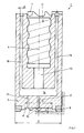
- Fig. 1 shows an axial section through a drill head 1, with a front part designated as drill bit 3.
- the drill head is rotationally symmetrical and has a longitudinal axis 4.
- the front face of the drill bit 6 is provided with drilling elements 9 arranged symmetrically with respect to the longitudinal axis 4, the cutting edges of which run essentially radially.
- This front surface 6 furthermore has guide cams 10 which are provided radially inside the drilling members 9 and which are arranged asymmetrically with respect to the longitudinal axis 4.
- FIG. 3 The shape of the rear drill head end surface 7 is seen in supervision in Fig. 3.
- This figure also shows a central threaded bore 11 with a special thread for connecting the drill head 1 to the drill pipe (not shown).
- an inflow bore 13 to the drill bit 3 can be seen, which forms the continuation of an inflow channel in the drill pipe.
- This central inflow bore 13 opens into a distribution chamber 14, from which, with respect to the longitudinal axis 4, symmetrical and essentially parallel to it run propellant air channels 16, while in the middle a wash channel 17 opens out from the distribution chamber 14 into the drill bit front surface 6.
- flushing channels 17 essentially parallel to the longitudinal axis 4, wherein these flushing channels 17 can run symmetrically or optionally asymmetrically to the longitudinal axis 14.
- air with a supercritical pressure is supplied through the inflow bore 13 into the distribution chamber 14 through the central feed channel of the drill pipe, wherein there is normally also a supercritical air pressure in the distribution chamber 14, which allows the air from the propellant air channels 16 to travel at the speed of sound at most , flows essentially parallel to the longitudinal axis 4.
- the air emerging from the wash channel 17 in the drilling direction also has at most the speed of sound. After it emerges between the drill base and the front face 6 of the drill bit, it becomes 90 ° deflected and flows essentially radially outwards, their speed decreasing in accordance with the widening flow cross section.
- This air from the floating channel 17 - it can, as mentioned, also be several such channels - conveys the cuttings in the direction towards the outer edge of the drill bit front surface 6, this movement being supported by the outwardly increasing rotational speed of the drill head 1.
- the air speed from the wash channel 17 has reached such a low value that its kinetic energy is no longer able to uncover hollows in its flow direction even on soft soils and in particular also on gravel soils, which as known, would hinder the conveying process of the cuttings to be conveyed pneumatically.
- this air speed or the air quantity is large enough to convey the cuttings as far as possible into the area of the driving air ducts 16, the air jets of which then ensure that the cuttings climb up in the pneumatic transport process.
- the floating channel 17 preferably has a diameter of 1.5 to 4 mm with a drill bit front surface diameter of 80 to 110 mm. It has proven to be advantageous, in particular for an outer diameter of the drill bit front surface of 89 mm, to have a mouth diameter of the floating channel 17 of 2 mm.
- the operating pressure of the compressed air fed to the drill head is between 6 and 20 bar, whereby at a pressure of 10 bar an air consumption of approximately 10m3 / min is required.
- the drilling head described also has no laterally opening bores and no bores through which air emerges with a radial component which is noticeable with respect to the longitudinal axis 4.
- Diagram 4 shows the outer diameter D of the drill bit from 80 to 110mm as a parameter depending on the speeds c x between the front face of the drill bit and the ground, which are safe or relevant for the hollowing out of the side walls Function of the outlet diameter d of the floating channel 17 specified. From the continuity equation it follows that with a diameter of the drill bit front surface of D x and a corresponding speed c x , with a gap height of h (FIG. 1) between the drill bit front surface 6 and the earth approximately the relationship applies, for example the speed of sound can mean what leads to the choice area shown in FIG. 4.
Landscapes
- Engineering & Computer Science (AREA)
- Life Sciences & Earth Sciences (AREA)
- Geology (AREA)
- Mining & Mineral Resources (AREA)
- Mechanical Engineering (AREA)
- Physics & Mathematics (AREA)
- Environmental & Geological Engineering (AREA)
- Fluid Mechanics (AREA)
- General Life Sciences & Earth Sciences (AREA)
- Geochemistry & Mineralogy (AREA)
- Earth Drilling (AREA)
Applications Claiming Priority (2)
| Application Number | Priority Date | Filing Date | Title |
|---|---|---|---|
| CH456689 | 1989-12-20 | ||
| CH4566/89 | 1989-12-20 |
Publications (1)
| Publication Number | Publication Date |
|---|---|
| EP0434009A1 true EP0434009A1 (fr) | 1991-06-26 |
Family
ID=4278475
Family Applications (1)
| Application Number | Title | Priority Date | Filing Date |
|---|---|---|---|
| EP90124676A Withdrawn EP0434009A1 (fr) | 1989-12-20 | 1990-12-19 | Trepan et procédé de forage |
Country Status (1)
| Country | Link |
|---|---|
| EP (1) | EP0434009A1 (fr) |
Cited By (1)
| Publication number | Priority date | Publication date | Assignee | Title |
|---|---|---|---|---|
| RU2347884C2 (ru) * | 2003-06-12 | 2009-02-27 | Шелл Интернэшнл Рисерч Маатсхаппий Б.В. | Ударное буровое долото, бурильная система и способ бурения скважины в подземной формации |
Citations (6)
| Publication number | Priority date | Publication date | Assignee | Title |
|---|---|---|---|---|
| US1764989A (en) * | 1927-03-14 | 1930-06-17 | Carl A Signell | Drill |
| US3299974A (en) * | 1963-10-01 | 1967-01-24 | P & V Mining & Engineering Ltd | Percussive drill bits |
| GB1071418A (en) * | 1963-08-19 | 1967-06-07 | P & V Mining & Engineering Ltd | Improvements in rock-drilling tools |
| US3542142A (en) * | 1968-09-27 | 1970-11-24 | Gulf Research Development Co | Method of drilling and drill bit therefor |
| US4231283A (en) * | 1978-11-01 | 1980-11-04 | Messerschmitt-Bolkow-Blohm Gesellschaft Mit Beschrankter Haftung | Pulsating liquid jet gun and method of operating the same |
| US4499957A (en) * | 1982-11-22 | 1985-02-19 | Gerald Adcock | Method for removing earth cuttings from holes being formed by a pneumatically exhausted drill tool |
-
1990
- 1990-12-19 EP EP90124676A patent/EP0434009A1/fr not_active Withdrawn
Patent Citations (6)
| Publication number | Priority date | Publication date | Assignee | Title |
|---|---|---|---|---|
| US1764989A (en) * | 1927-03-14 | 1930-06-17 | Carl A Signell | Drill |
| GB1071418A (en) * | 1963-08-19 | 1967-06-07 | P & V Mining & Engineering Ltd | Improvements in rock-drilling tools |
| US3299974A (en) * | 1963-10-01 | 1967-01-24 | P & V Mining & Engineering Ltd | Percussive drill bits |
| US3542142A (en) * | 1968-09-27 | 1970-11-24 | Gulf Research Development Co | Method of drilling and drill bit therefor |
| US4231283A (en) * | 1978-11-01 | 1980-11-04 | Messerschmitt-Bolkow-Blohm Gesellschaft Mit Beschrankter Haftung | Pulsating liquid jet gun and method of operating the same |
| US4499957A (en) * | 1982-11-22 | 1985-02-19 | Gerald Adcock | Method for removing earth cuttings from holes being formed by a pneumatically exhausted drill tool |
Non-Patent Citations (1)
| Title |
|---|
| "Composite catalog of oil field equipment and services", Auflage 38, Band 3, 1988, Seiten 3346-3348, Gulf Publishing Co., Houston, US * |
Cited By (1)
| Publication number | Priority date | Publication date | Assignee | Title |
|---|---|---|---|---|
| RU2347884C2 (ru) * | 2003-06-12 | 2009-02-27 | Шелл Интернэшнл Рисерч Маатсхаппий Б.В. | Ударное буровое долото, бурильная система и способ бурения скважины в подземной формации |
Similar Documents
| Publication | Publication Date | Title |
|---|---|---|
| DE3113109C2 (de) | Drehbohrmeißel für Tiefbohrungen | |
| DE60306757T2 (de) | Schlagbohrmeissel und einsatz dafür | |
| DE69017293T2 (de) | Bohrvorrichtung mit verbesserter hydraulischer Wirkung zur Führung der Bohrflüssigkeit. | |
| DE2802869A1 (de) | Bohrwerkzeug mit saugstrahl | |
| DE2629695A1 (de) | Vorrichtung zum bohren von erdloechern | |
| DE69106192T2 (de) | Drehbohrmeissel mit nach aussen gerichteten Düsen. | |
| DE2540558A1 (de) | Bohrgeraet | |
| DE1533644B2 (de) | Verfahren und Vorrichtung zum annähernd waagerechten Durchbohren von Dämmen aus Erd- oder Gesteinsschichten | |
| DE19712181B4 (de) | Bohrkrone | |
| DE2063567C3 (de) | Vorrichtung zum Erweitern eines durch Verdrängung und Verdichtung von Erdreich hergestellten Vorbohrlochs | |
| DE2343080A1 (de) | Bohrverfahren und vorrichtung zu seiner durchfuehrung | |
| WO1988004352A2 (fr) | Procede pour realiser un puits | |
| DE2758385C3 (de) | Schlag-Bohreinrichtung für Großlochbohrungen | |
| EP0434009A1 (fr) | Trepan et procédé de forage | |
| DE2541439A1 (de) | Strahlpumpe | |
| DE1299255B (de) | Verfahren zum Bohren im Erdreich und Bohrer zum Ausueben des Verfahrens | |
| EP0795678A1 (fr) | Dispositif d'élargissement de la section d'un forage pilote | |
| EP0141117B2 (fr) | Procédé pour forer un fond de gravier ou de roche et foret pour sa mise en oevre | |
| EP0334806A1 (fr) | Couronne de forage de roche | |
| DE2410217C2 (de) | Drehbohrwerkzeug zum hydraulischen Bohren von Löchern in unterirdische Formationen | |
| DE2052168A1 (de) | Bohrverfahren und vorrichtung | |
| DE3738942C2 (fr) | ||
| DE3302117C2 (fr) | ||
| EP0764761A1 (fr) | Machine de forage de tunnels | |
| AT216445B (de) | Tiefbohrvorrichtung |
Legal Events
| Date | Code | Title | Description |
|---|---|---|---|
| PUAI | Public reference made under article 153(3) epc to a published international application that has entered the european phase |
Free format text: ORIGINAL CODE: 0009012 |
|
| AK | Designated contracting states |
Kind code of ref document: A1 Designated state(s): AT BE CH DE DK ES FR GB GR IT LI LU NL SE |
|
| 17P | Request for examination filed |
Effective date: 19911223 |
|
| 17Q | First examination report despatched |
Effective date: 19921208 |
|
| STAA | Information on the status of an ep patent application or granted ep patent |
Free format text: STATUS: THE APPLICATION IS DEEMED TO BE WITHDRAWN |
|
| 18D | Application deemed to be withdrawn |
Effective date: 19930619 |