EP0434076B1 - Insert pour une chaussure - Google Patents
Insert pour une chaussure Download PDFInfo
- Publication number
- EP0434076B1 EP0434076B1 EP90125039A EP90125039A EP0434076B1 EP 0434076 B1 EP0434076 B1 EP 0434076B1 EP 90125039 A EP90125039 A EP 90125039A EP 90125039 A EP90125039 A EP 90125039A EP 0434076 B1 EP0434076 B1 EP 0434076B1
- Authority
- EP
- European Patent Office
- Prior art keywords
- insert
- insert according
- foot
- region
- sole
- Prior art date
- Legal status (The legal status is an assumption and is not a legal conclusion. Google has not performed a legal analysis and makes no representation as to the accuracy of the status listed.)
- Expired - Lifetime
Links
- 210000002683 foot Anatomy 0.000 claims abstract description 23
- 210000004744 fore-foot Anatomy 0.000 claims abstract description 5
- 239000000463 material Substances 0.000 claims description 9
- 210000001255 hallux Anatomy 0.000 claims description 2
- 210000000453 second toe Anatomy 0.000 claims description 2
- 210000003371 toe Anatomy 0.000 claims description 2
- 238000013016 damping Methods 0.000 abstract description 5
- 229910000639 Spring steel Inorganic materials 0.000 description 6
- 230000000694 effects Effects 0.000 description 3
- 229910000831 Steel Inorganic materials 0.000 description 2
- 239000002184 metal Substances 0.000 description 2
- 238000005293 physical law Methods 0.000 description 2
- 238000007493 shaping process Methods 0.000 description 2
- 239000010959 steel Substances 0.000 description 2
- 238000005452 bending Methods 0.000 description 1
- 238000004049 embossing Methods 0.000 description 1
- 230000005484 gravity Effects 0.000 description 1
- 230000001771 impaired effect Effects 0.000 description 1
- 238000001746 injection moulding Methods 0.000 description 1
- 238000004519 manufacturing process Methods 0.000 description 1
- RZSCFTDHFNHMOR-UHFFFAOYSA-N n-(2,4-difluorophenyl)-2-[3-(trifluoromethyl)phenoxy]pyridine-3-carboxamide;1,1-dimethyl-3-(4-propan-2-ylphenyl)urea Chemical compound CC(C)C1=CC=C(NC(=O)N(C)C)C=C1.FC1=CC(F)=CC=C1NC(=O)C1=CC=CN=C1OC1=CC=CC(C(F)(F)F)=C1 RZSCFTDHFNHMOR-UHFFFAOYSA-N 0.000 description 1
- 238000004080 punching Methods 0.000 description 1
- 230000002787 reinforcement Effects 0.000 description 1
Images


Classifications
-
- A—HUMAN NECESSITIES
- A43—FOOTWEAR
- A43B—CHARACTERISTIC FEATURES OF FOOTWEAR; PARTS OF FOOTWEAR
- A43B13/00—Soles; Sole-and-heel integral units
- A43B13/14—Soles; Sole-and-heel integral units characterised by the constructive form
- A43B13/141—Soles; Sole-and-heel integral units characterised by the constructive form with a part of the sole being flexible, e.g. permitting articulation or torsion
-
- A—HUMAN NECESSITIES
- A43—FOOTWEAR
- A43B—CHARACTERISTIC FEATURES OF FOOTWEAR; PARTS OF FOOTWEAR
- A43B13/00—Soles; Sole-and-heel integral units
- A43B13/38—Built-in insoles joined to uppers during the manufacturing process, e.g. structural insoles; Insoles glued to shoes during the manufacturing process
-
- A—HUMAN NECESSITIES
- A43—FOOTWEAR
- A43B—CHARACTERISTIC FEATURES OF FOOTWEAR; PARTS OF FOOTWEAR
- A43B17/00—Insoles for insertion, e.g. footbeds or inlays, for attachment to the shoe after the upper has been joined
Definitions
- the invention relates to an insert for a shoe according to the preamble of claim 1.
- an insert for a shoe according to the preamble of claim 1.
- Such an insert is known from German utility model DE-U-88 15 448, which corresponds to the subsequently published EP 0 373 336 A1, and consists of hard, resilient Plate material, preferably of uniform thickness, which has a transverse profile running transversely to the longitudinal direction of the sole, the insert extending over the entire extent of the sole of the foot.
- This insert is suitable for a wide variety of shoes, such as street shoes, sports shoes, boots, sandals, sandals, sneakers or the like.
- the insert and sole according to the present invention can, moreover, optionally have all the features of the insert and sole of the layer-forming document, unless these features are excluded by the present inventive features in the respective embodiment of the present invention, and for this purpose the entire content the generic document and the above-mentioned corresponding European patent application made by this reference with the disclosure content of the present documents.
- the object of the present invention is, in particular, to design an insert and a shoe provided with an insert of the above type in such a way that the biomechanical and physical laws are not significantly impaired by the walk or walked with shoes and, moreover, their support is preferably even supported and promoted , so that it is preferred to make available an insert which corresponds to a great extent to these biomechanical and physical laws and which, when used as a sole, results in shoes which, in accordance with the respective practical provision, result in the best possible effect of these laws in practice.
- the task of a shoe is to guide the foot, to support it, to cushion the impact and to serve the foot as a tool. These tasks are very diverse and cannot be optimally performed by a shoe. This can be seen from the fact that a large number of shoes are designed for special areas of application. There are mountain shoes, indoor sports shoes, tennis shoes, javelin shoes, ski shoes, boxing shoes, soccer shoes, golf shoes and many more.
- a hard insert or insole which preferably consists of metal, in particular spring steel.
- This insert or insole is designed in such a way that it has transverse profiles transverse to the longitudinal direction of the foot, which make this insert or insole movable in the longitudinal direction, still give it a certain amount of torsional freedom, but keep it largely stable in the transverse direction.
- This insole or insole shows many advantages, but it does not or does not take sufficient account of many peculiarities of the biomechanical laws, especially the sport-specific loads.
- the object of the present invention is therefore, in particular, to provide an insert and its use as a sole which is designed in special areas in such a way that sports-specific and / or foot-appropriate loads are made possible which the insert or sole proposed in the prior art does not enables.
- This object is solved by the features of claim 1.
- transverse profile extends essentially or approximately perpendicular to the line of the force application points or comprises several areas of different inclination to the longitudinal axis of the insert.
- the amortization phase which is the phase in which the foot stands on the floor while running, at the moment of the dynamic running movement.
- the line of force application points winds from the point of impact over the center of the heel in the area of the outer edge of the foot, from there to the center of the ball and from there to the big toe or the second toe.
- the line of the force application points is changed and the foot is brought into a constrained position by a relatively rigid, generic insert, in particular made of spring steel, with flat corrugations or other profiles.
- the relevant development of the insert proposed according to the species should be designed according to the invention in such a way that the profiling of the insert runs perpendicularly or approximately perpendicularly to the line of the force application points and not perpendicularly to the longitudinal axis of the sole.
- This profiling may run along the line of the gravity plummet, but must run approximately across the line of the force application points, because then the ground reaction forces can be most safely transferred to the foot or from the foot to the floor. This in turn should have an accelerating effect on the runner's foot.
- the insert according to the invention can be used as an insole or as part of an insole; or as an insole or as part of an insole; or used as a sole reinforcement connected to a sole.
- FIG. 1 shows an insert 1, which consists of a central, longitudinal core 2 which, in accordance with the insert proposed in EP 0 373 336, has a meandering transverse profile.
- 1 shows the course of the line of the force application points and the profiling directions approximately perpendicular to the course of the line of the force application points 22.
- Lips 3 (FIG. 2) can be provided on this central core 2 or longitudinal element, which go to the outer edge of the foot and which do not be more involved in the wavy structure, but run smoothly.
- the lips 3 can have different lengths and different widths, namely in accordance with a locally different damping behavior, as is required.
- the lips 3 are through recesses 6 formed in the profiling of the insert 1 and in this insert form distributed over the entire length of the insert both on the inside and on the outside.
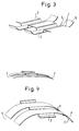
- FIG. 2 shows an oblique view of part of the insert 1 of FIG. 1, the material preferably consisting of spring steel and the lips 3 being flat in the present case.
- FIG. 3 shows a section of the insert 1 of FIG. 1, the meandering configuration of the main piece 2 of the binary layer 1 being recognizable.
- the lips or plates 3 are bent upwards in the region of their ends 16.
- FIG. 4 also shows a partial section of the insert 1 with the core piece 2.
- the lips 3 are bent downward in the end region 17 and produce a groove which is open at the bottom, whereby a trampoline effect is brought about under axial load. It is different from shoe to shoe specificity whether the plates or lips 3 come to rest on the upper or lower part of the meander.
- FIG. 5 shows a two-part insert, consisting of the forefoot part 18 and the rear foot part 19, which are independent of one another and are connected to one another by means of a torsion element 20, namely on riveted plates 21. No other detailed embodiment of the insert is shown.
- FIG. 6 shows a toe cap 33 riveted onto the insert 1 (not shown in more detail) in a top view and an oblique view.
- FIG. 7 shows the rear foot area of a meandering profiled insert 1 made of spring steel.
- a steel spring element 39 projects into the interior of the shoe and is fixed on the outside with a rivet 34 on the insert 1.
- a damping element can be accommodated in the intermediate space 40.
- the insert 1 from FIG. 1, which is also shown in FIG. 2, is preferably foamed or installed in a shoe sole.
- the gaps created by the profiling are preferably foamed or provided with other material.
- the lips 3 can then bend upwards under load and then take with them the sole material and shaft material which is located on the outside of the foot. Thanks to their bending, they allow better contact between the outside or inside of the foot and the floor when there is a corresponding load. Due to the different design of the plates or lips 3 in terms of their length and width, the warping behavior can be designed differently depending on the sport.
- the hard, resilient plate material from which the insert 1 according to the invention is made can be metal and / or plastic plate material, preferably steel sheet, particularly preferably spring steel sheet. Furthermore, the hard, resilient plate material preferably has a thickness between 0.1 and 1.5 mm, particularly preferably between 0.3 and 0.5 mm.
- the transverse profiling which is not shown in all the figures of the drawing for reasons of the simplified illustration, but, unless stated otherwise, extends over the entire insert, can have grooves, grooves, ribs, grooves, waves, in cross-section. , be corrugated or beaded, preferably meandering, trapezoidal, zigzag or meandering.
- the width of the periodically repeating cross-section elements is preferably 3 mm to 20 mm, more preferably 6 mm to 16 mm, particularly preferably 8 mm to 13 mm.
Landscapes
- Footwear And Its Accessory, Manufacturing Method And Apparatuses (AREA)
Claims (12)
- Insert de semelle pour une chaussure, réalisé en un matériau en forme de plaque, dur et élastique, qui présente un profilage transversal qui s'étend perpendiculairement à la direction longitudinale de la semelle, présentant la particularité suivante :- l'insert (1) s'étend sur l'extension totale de la plante du pied,
caractérisé par les éléments suivants :- lors de la marche apparaissent des points d'attaque de forces le long d'une ligne en méandres (22), laquelle s'étend depuis le point d'engagement et via le centre du talon dans la région du bord extérieur du pied, et de celui-ci jusqu'au centre du bourrelet, puis de celui-ci jusqu'au gros orteil ou jusqu'au second orteil, et- le profilage transversal s'étend sensiblement perpendiculairement à la ligne (22) des points d'attaque de forces. - Insert de semelle selon la revendication 1, caractérisé en ce que des évidements (6) sont présents au niveau du côté extérieur et/ou intérieur.
- Insert de semelle selon l'une ou l'autre des revendications 1 et 2, caractérisé en ce que l'insert (1) a la forme d'un squelette, du fait qu'il est évidé dans des régions prédéterminées.
- Insert de semelle selon l'une des revendications 1 à 3, caractérisé en ce que des fentes sont ménagées dans la région de la plante.
- Insert de semelle selon l'une des revendications 1 à 4, caractérisé en ce que dans la région du talon (19) de l'insert (1) et/ou de la partie antérieure du pied (18) sont intégrés un ou plusieurs éléments d'amortissement, ou bien sont prévus un ou plusieurs évidements (4) pour le logement d'éléments d'amortissement.
- Insert de semelle selon l'une des revendications 2 à 5, caractérisé en ce que des languettes (3), qui s'étendent vers l'intérieur ou vers l'extérieur dans la direction du profilage, sont formées par les évidements (6).
- Insert de semelle selon la revendication 6, caractérisé en ce que les languettes (3) sont préalablement cintrées, et/ou en ce qu'elles présentent une certaine précontrainte.
- Insert de semelle selon l'une des revendications 2 à 7, caractérisé en ce que la largeur et/ou la profondeur des évidements (6) sont différentes, et/ou en ce que les nombres des évidements (6) du côté intérieur et du côté extérieur du pied sont différents.
- Insert de semelle selon l'une des revendications 1 à 5, caractérisé en ce que le contour de l'insert (1) est plus petit que le contour de la semelle correspondante.
- Insert de semelle selon l'une des revendications 1 à 5, caractérisé en ce que l'insert (1) est constitué de deux éléments séparés (18, 19) qui sont reliés fermement l'un à l'autre dans la région de la pièce d'articulation avec une barre de torsion (20) ou d'une autre manière.
- Insert de semelle selon l'une des revendications 1 à 5, caractérisé en ce qu'il est prévu des fentes parallèles à la direction du profilage et/ou des fentes perpendiculaires à la direction du profilage ou s'étendant transversalement d'une autre manière.
- Insert selon l'une ou plusieurs des revendications précédentes, caractérisé en ce qu'un capuchon à orteils fixe (33) est relié solidairement à l'insert (1)
Applications Claiming Priority (2)
| Application Number | Priority Date | Filing Date | Title |
|---|---|---|---|
| DE3942094A DE3942094A1 (de) | 1989-12-20 | 1989-12-20 | Einlage und brandsohle fuer einen schuh |
| DE3942094 | 1989-12-20 |
Publications (3)
| Publication Number | Publication Date |
|---|---|
| EP0434076A2 EP0434076A2 (fr) | 1991-06-26 |
| EP0434076A3 EP0434076A3 (en) | 1992-01-15 |
| EP0434076B1 true EP0434076B1 (fr) | 1997-09-24 |
Family
ID=6395902
Family Applications (1)
| Application Number | Title | Priority Date | Filing Date |
|---|---|---|---|
| EP90125039A Expired - Lifetime EP0434076B1 (fr) | 1989-12-20 | 1990-12-20 | Insert pour une chaussure |
Country Status (3)
| Country | Link |
|---|---|
| EP (1) | EP0434076B1 (fr) |
| AT (1) | ATE158480T1 (fr) |
| DE (2) | DE3942094A1 (fr) |
Cited By (1)
| Publication number | Priority date | Publication date | Assignee | Title |
|---|---|---|---|---|
| EP1602294A1 (fr) | 2004-06-02 | 2005-12-07 | Spannrit Schuhkomponenten GmbH | Semelle intérieure en polyuréthane et procédé de fabrication |
Families Citing this family (20)
| Publication number | Priority date | Publication date | Assignee | Title |
|---|---|---|---|---|
| IT1274345B (it) * | 1994-04-12 | 1997-07-17 | Nordica Spa | Dispositivo di irrobustimento della suola, particolarmente per calzature sportive. |
| AU7831994A (en) * | 1994-08-12 | 1996-03-07 | One Sport, Inc. | Footwear |
| AU2899397A (en) * | 1996-05-30 | 1998-01-05 | Achim Mayer | Shoe, method of manufacturing it and its use |
| US5915820A (en) * | 1996-08-20 | 1999-06-29 | Adidas A G | Shoe having an internal chassis |
| IT1290354B1 (it) * | 1997-02-07 | 1998-10-22 | Vibram Spa | Suola biomeccanica |
| US6779282B2 (en) | 1998-12-23 | 2004-08-24 | Groehninger Frank Friedrich | Insole |
| AU1751099A (en) | 1998-12-23 | 2000-07-31 | Frank Friedrich Grohninger | Shoe insert |
| DE19904744B4 (de) * | 1999-02-05 | 2005-11-10 | Adidas International Marketing B.V. | Schuh |
| DE20021700U1 (de) | 2000-12-22 | 2001-03-01 | Heine, Götz, 87719 Mindelheim | Bekleidungselement |
| DE202005019691U1 (de) * | 2005-12-16 | 2007-04-26 | Bauerfeind Ag | Einlegesohle |
| WO2008144446A1 (fr) * | 2007-05-18 | 2008-11-27 | The North Face Apparel Corp. | Dispositif formant plaque de support pour chaussures |
| DE202008018366U1 (de) | 2008-11-26 | 2013-07-17 | Helmut Mayer Gbr Mbh | Einlegesohle |
| DE102008059030B4 (de) * | 2008-11-26 | 2014-09-25 | Helmut Mayer Gbr Mbh | Einlegesohle |
| DE102010049298A1 (de) * | 2010-10-22 | 2012-04-26 | Fa. Mayer Gbr (Vertretungsberechtigte Gesellschafter: Herr Helmut Mayer, 88045 Friedrichshafen) | Sicherheitsschuh mit Schutzkappe |
| DE102011109274A1 (de) * | 2011-08-03 | 2013-02-07 | Mayer GbR (Vertretungsberechtigter Gesellschafter: Herr Helmut Mayer, 88045 Friedrichshafen) | Sohlenchassis für Schuhe |
| DE102012004631A1 (de) * | 2012-03-06 | 2013-09-12 | Mayer GbR (Vertretungsberechtigter Gesellschafter: Herr Helmut Mayer, 88045 Friedrichshafen) | Sportsandale oder Schutzschuh |
| WO2013167155A1 (fr) * | 2012-05-09 | 2013-11-14 | Norbert Schmid Gmbh & Co. Kg | Semelle intérieure pour chaussures |
| US9241535B2 (en) | 2013-03-14 | 2016-01-26 | Nike, Inc. | Sole structures and articles incorporating same |
| ITUA20164633A1 (it) * | 2016-06-24 | 2017-12-24 | Diadora Sport S R L | Lamina anti-perforazione per calzature |
| US12302980B2 (en) | 2023-05-31 | 2025-05-20 | Wolverine Outdoors, Inc. | Footwear sole and related method of use |
Family Cites Families (2)
| Publication number | Priority date | Publication date | Assignee | Title |
|---|---|---|---|---|
| CH246465A (fr) * | 1945-10-02 | 1947-01-15 | Soc D Rech Et D Applic Tech | Chaussure. |
| DE1075012B (de) * | 1958-01-07 | 1960-02-04 | Johannes Schaller, Lmdenfels (Odenw | I Schuhwerk mit mindestens einer im Gelenkbereich Ausschnitte auf weisenden Sohle |
-
1989
- 1989-12-20 DE DE3942094A patent/DE3942094A1/de not_active Withdrawn
-
1990
- 1990-12-20 AT AT90125039T patent/ATE158480T1/de active
- 1990-12-20 DE DE59010763T patent/DE59010763D1/de not_active Expired - Fee Related
- 1990-12-20 EP EP90125039A patent/EP0434076B1/fr not_active Expired - Lifetime
Cited By (1)
| Publication number | Priority date | Publication date | Assignee | Title |
|---|---|---|---|---|
| EP1602294A1 (fr) | 2004-06-02 | 2005-12-07 | Spannrit Schuhkomponenten GmbH | Semelle intérieure en polyuréthane et procédé de fabrication |
Also Published As
| Publication number | Publication date |
|---|---|
| ATE158480T1 (de) | 1997-10-15 |
| EP0434076A2 (fr) | 1991-06-26 |
| DE59010763D1 (de) | 1997-10-30 |
| EP0434076A3 (en) | 1992-01-15 |
| DE3942094A1 (de) | 1991-06-27 |
Similar Documents
| Publication | Publication Date | Title |
|---|---|---|
| EP0434076B1 (fr) | Insert pour une chaussure | |
| DE69224050T2 (de) | Mehrschichtige Sportschuhsohle | |
| DE19950121C1 (de) | Sohle | |
| DE69005190T2 (de) | Sportschuh mit elastischem Einsatz im Absatz. | |
| DE60027500T2 (de) | Schuh | |
| DE102014215897B4 (de) | adistar boost | |
| EP0373336B1 (fr) | Pièce d'insertion pour chaussure | |
| DE69120805T2 (de) | Sportschuhsohle | |
| DE3508308C2 (de) | Sportschuh | |
| DE19953147B4 (de) | Stoßabsorberstruktur für Schuhsohlen | |
| DE102020125150A1 (de) | Sohlenkonstruktion für einen schuh | |
| EP4331423A2 (fr) | Semelle d'usure dotée d'une semelle intermédiaire souple | |
| CH638962A5 (de) | Langlaufschischuh. | |
| DE29903764U1 (de) | Schuh | |
| DE102011102849A1 (de) | Schuhsole mit Röhren | |
| DE3440206A1 (de) | Schuhsohlenanordnung | |
| DE102019107402A1 (de) | Zwischensohlenkonstruktion für einen Schuh | |
| DE112005003570T5 (de) | Stoßabsorptionsvorrichtung für Schuhsohle | |
| DE3933717A1 (de) | Schi mit relativ zum kern verstellbaren tragschichtteil | |
| DE69621402T3 (de) | Rollschuhgestell und Verfahren zu seiner Herstellung | |
| DE3120349A1 (de) | Golfschuhe | |
| WO1996035488A1 (fr) | Dispositif de fixation d'une planche a neige a la chaussure de son utilisateur | |
| DE69103497T2 (de) | Langlaufski, insbesondere für die Praxis des abwechselnden Schrittes. | |
| DE60319631T2 (de) | Gleitgerät mit zwei Wänden | |
| DE2927059A1 (de) | Skischuh mit integrierter skibindung |
Legal Events
| Date | Code | Title | Description |
|---|---|---|---|
| PUAI | Public reference made under article 153(3) epc to a published international application that has entered the european phase |
Free format text: ORIGINAL CODE: 0009012 |
|
| AK | Designated contracting states |
Kind code of ref document: A2 Designated state(s): AT BE CH DE DK ES FR GB GR IT LI LU NL SE |
|
| RIN1 | Information on inventor provided before grant (corrected) |
Inventor name: MAYER, HELMUT |
|
| PUAL | Search report despatched |
Free format text: ORIGINAL CODE: 0009013 |
|
| AK | Designated contracting states |
Kind code of ref document: A3 Designated state(s): AT BE CH DE DK ES FR GB GR IT LI LU NL SE |
|
| 17P | Request for examination filed |
Effective date: 19920707 |
|
| 17Q | First examination report despatched |
Effective date: 19930914 |
|
| GRAG | Despatch of communication of intention to grant |
Free format text: ORIGINAL CODE: EPIDOS AGRA |
|
| GRAH | Despatch of communication of intention to grant a patent |
Free format text: ORIGINAL CODE: EPIDOS IGRA |
|
| GRAH | Despatch of communication of intention to grant a patent |
Free format text: ORIGINAL CODE: EPIDOS IGRA |
|
| GRAA | (expected) grant |
Free format text: ORIGINAL CODE: 0009210 |
|
| AK | Designated contracting states |
Kind code of ref document: B1 Designated state(s): AT BE CH DE DK ES FR GB GR IT LI LU NL SE |
|
| PG25 | Lapsed in a contracting state [announced via postgrant information from national office to epo] |
Ref country code: IT Free format text: LAPSE BECAUSE OF FAILURE TO SUBMIT A TRANSLATION OF THE DESCRIPTION OR TO PAY THE FEE WITHIN THE PRE;WARNING: LAPSES OF ITALIAN PATENTS WITH EFFECTIVE DATE BEFORE 2007 MAY HAVE OCCURRED AT ANY TIME BEFORE 2007. THE CORRECT EFFECTIVE DATE MAY BE DIFFERENT FROM THE ONE RECORDED.SCRIBED TIME-LIMIT Effective date: 19970924 Ref country code: FR Free format text: LAPSE BECAUSE OF FAILURE TO SUBMIT A TRANSLATION OF THE DESCRIPTION OR TO PAY THE FEE WITHIN THE PRESCRIBED TIME-LIMIT Effective date: 19970924 Ref country code: NL Free format text: LAPSE BECAUSE OF FAILURE TO SUBMIT A TRANSLATION OF THE DESCRIPTION OR TO PAY THE FEE WITHIN THE PRESCRIBED TIME-LIMIT Effective date: 19970924 Ref country code: GR Free format text: LAPSE BECAUSE OF FAILURE TO SUBMIT A TRANSLATION OF THE DESCRIPTION OR TO PAY THE FEE WITHIN THE PRESCRIBED TIME-LIMIT Effective date: 19970924 Ref country code: GB Free format text: LAPSE BECAUSE OF FAILURE TO SUBMIT A TRANSLATION OF THE DESCRIPTION OR TO PAY THE FEE WITHIN THE PRESCRIBED TIME-LIMIT Effective date: 19970924 Ref country code: DK Free format text: LAPSE BECAUSE OF NON-PAYMENT OF DUE FEES Effective date: 19970924 Ref country code: ES Free format text: THE PATENT HAS BEEN ANNULLED BY A DECISION OF A NATIONAL AUTHORITY Effective date: 19970924 |
|
| REF | Corresponds to: |
Ref document number: 158480 Country of ref document: AT Date of ref document: 19971015 Kind code of ref document: T |
|
| REG | Reference to a national code |
Ref country code: CH Ref legal event code: EP |
|
| REF | Corresponds to: |
Ref document number: 59010763 Country of ref document: DE Date of ref document: 19971030 |
|
| PG25 | Lapsed in a contracting state [announced via postgrant information from national office to epo] |
Ref country code: AT Free format text: LAPSE BECAUSE OF NON-PAYMENT OF DUE FEES Effective date: 19971220 Ref country code: LU Free format text: LAPSE BECAUSE OF NON-PAYMENT OF DUE FEES Effective date: 19971220 |
|
| PG25 | Lapsed in a contracting state [announced via postgrant information from national office to epo] |
Ref country code: SE Effective date: 19971224 |
|
| PG25 | Lapsed in a contracting state [announced via postgrant information from national office to epo] |
Ref country code: BE Free format text: LAPSE BECAUSE OF NON-PAYMENT OF DUE FEES Effective date: 19971231 Ref country code: CH Free format text: LAPSE BECAUSE OF NON-PAYMENT OF DUE FEES Effective date: 19971231 Ref country code: LI Free format text: LAPSE BECAUSE OF NON-PAYMENT OF DUE FEES Effective date: 19971231 |
|
| EN | Fr: translation not filed | ||
| NLV1 | Nl: lapsed or annulled due to failure to fulfill the requirements of art. 29p and 29m of the patents act | ||
| GBV | Gb: ep patent (uk) treated as always having been void in accordance with gb section 77(7)/1977 [no translation filed] |
Effective date: 19970924 |
|
| BERE | Be: lapsed |
Owner name: MAYER HELMUT Effective date: 19971231 |
|
| PLBE | No opposition filed within time limit |
Free format text: ORIGINAL CODE: 0009261 |
|
| STAA | Information on the status of an ep patent application or granted ep patent |
Free format text: STATUS: NO OPPOSITION FILED WITHIN TIME LIMIT |
|
| REG | Reference to a national code |
Ref country code: CH Ref legal event code: PL |
|
| 26N | No opposition filed | ||
| PGFP | Annual fee paid to national office [announced via postgrant information from national office to epo] |
Ref country code: DE Payment date: 20061214 Year of fee payment: 17 |
|
| PG25 | Lapsed in a contracting state [announced via postgrant information from national office to epo] |
Ref country code: DE Free format text: LAPSE BECAUSE OF NON-PAYMENT OF DUE FEES Effective date: 20080701 |