EP0434105B1 - Vorrichtung zum Füllen eines Hohlraumes - Google Patents
Vorrichtung zum Füllen eines Hohlraumes Download PDFInfo
- Publication number
- EP0434105B1 EP0434105B1 EP90203025A EP90203025A EP0434105B1 EP 0434105 B1 EP0434105 B1 EP 0434105B1 EP 90203025 A EP90203025 A EP 90203025A EP 90203025 A EP90203025 A EP 90203025A EP 0434105 B1 EP0434105 B1 EP 0434105B1
- Authority
- EP
- European Patent Office
- Prior art keywords
- filling
- packaging
- mixture
- components
- filling tube
- Prior art date
- Legal status (The legal status is an assumption and is not a legal conclusion. Google has not performed a legal analysis and makes no representation as to the accuracy of the status listed.)
- Expired - Lifetime
Links
- 238000004806 packaging method and process Methods 0.000 claims abstract description 36
- 239000000203 mixture Substances 0.000 claims abstract description 25
- 238000004898 kneading Methods 0.000 claims abstract description 7
- 238000004891 communication Methods 0.000 claims abstract description 4
- 238000009459 flexible packaging Methods 0.000 claims abstract description 4
- 238000003780 insertion Methods 0.000 claims abstract description 3
- 230000037431 insertion Effects 0.000 claims abstract description 3
- 238000013022 venting Methods 0.000 claims description 7
- 230000007613 environmental effect Effects 0.000 abstract description 3
- 239000002894 chemical waste Substances 0.000 abstract description 2
- 239000011810 insulating material Substances 0.000 abstract description 2
- 239000002085 irritant Substances 0.000 abstract description 2
- 231100000021 irritant Toxicity 0.000 abstract description 2
- 239000007788 liquid Substances 0.000 abstract description 2
- 239000000463 material Substances 0.000 abstract description 2
- 239000000126 substance Substances 0.000 abstract description 2
- 239000002184 metal Substances 0.000 description 4
- 230000008878 coupling Effects 0.000 description 2
- 238000010168 coupling process Methods 0.000 description 2
- 238000005859 coupling reaction Methods 0.000 description 2
- 239000008240 homogeneous mixture Substances 0.000 description 2
- 239000002699 waste material Substances 0.000 description 2
- OKTJSMMVPCPJKN-UHFFFAOYSA-N Carbon Chemical compound [C] OKTJSMMVPCPJKN-UHFFFAOYSA-N 0.000 description 1
- 230000004888 barrier function Effects 0.000 description 1
- 229910052799 carbon Inorganic materials 0.000 description 1
- 238000010276 construction Methods 0.000 description 1
- 239000000945 filler Substances 0.000 description 1
- 230000000007 visual effect Effects 0.000 description 1
- 238000004804 winding Methods 0.000 description 1
Images

Classifications
-
- H—ELECTRICITY
- H02—GENERATION; CONVERSION OR DISTRIBUTION OF ELECTRIC POWER
- H02G—INSTALLATION OF ELECTRIC CABLES OR LINES, OR OF COMBINED OPTICAL AND ELECTRIC CABLES OR LINES
- H02G15/00—Cable fittings
- H02G15/003—Filling materials, e.g. solid or fluid insulation
-
- B—PERFORMING OPERATIONS; TRANSPORTING
- B65—CONVEYING; PACKING; STORING; HANDLING THIN OR FILAMENTARY MATERIAL
- B65D—CONTAINERS FOR STORAGE OR TRANSPORT OF ARTICLES OR MATERIALS, e.g. BAGS, BARRELS, BOTTLES, BOXES, CANS, CARTONS, CRATES, DRUMS, JARS, TANKS, HOPPERS, FORWARDING CONTAINERS; ACCESSORIES, CLOSURES, OR FITTINGS THEREFOR; PACKAGING ELEMENTS; PACKAGES
- B65D81/00—Containers, packaging elements, or packages, for contents presenting particular transport or storage problems, or adapted to be used for non-packaging purposes after removal of contents
- B65D81/32—Containers, packaging elements, or packages, for contents presenting particular transport or storage problems, or adapted to be used for non-packaging purposes after removal of contents for packaging two or more different materials which must be maintained separate prior to use in admixture
- B65D81/3261—Flexible containers having several compartments
- B65D81/3266—Flexible containers having several compartments separated by a common rupturable seal, a clip or other removable fastening device
-
- F—MECHANICAL ENGINEERING; LIGHTING; HEATING; WEAPONS; BLASTING
- F16—ENGINEERING ELEMENTS AND UNITS; GENERAL MEASURES FOR PRODUCING AND MAINTAINING EFFECTIVE FUNCTIONING OF MACHINES OR INSTALLATIONS; THERMAL INSULATION IN GENERAL
- F16G—BELTS, CABLES, OR ROPES, PREDOMINANTLY USED FOR DRIVING PURPOSES; CHAINS; FITTINGS PREDOMINANTLY USED THEREFOR
- F16G11/00—Means for fastening cables or ropes to one another or to other objects; Caps or sleeves for fixing on cables or ropes
- F16G11/02—Means for fastening cables or ropes to one another or to other objects; Caps or sleeves for fixing on cables or ropes with parts deformable to grip the cable or cables; Fastening means which engage a sleeve or the like fixed on the cable
-
- H—ELECTRICITY
- H02—GENERATION; CONVERSION OR DISTRIBUTION OF ELECTRIC POWER
- H02G—INSTALLATION OF ELECTRIC CABLES OR LINES, OR OF COMBINED OPTICAL AND ELECTRIC CABLES OR LINES
- H02G1/00—Methods or apparatus specially adapted for installing, maintaining, repairing or dismantling electric cables or lines
- H02G1/14—Methods or apparatus specially adapted for installing, maintaining, repairing or dismantling electric cables or lines for joining or terminating cables
Definitions
- the invention has for its object to provide a system for filling a cavity wherein all provisions of environmental legislation can be satisfied in simple manner, while nuisance or danger to persons working with the system is also virtually entirely eliminated.
- a known packaging consists for example of two cans, which may or may not be in integrated form, the contents whereof are combined and mixed. Harmful vapours may be released during this open mixing, while spillage can moreover not be ruled out. The remaining, not wholly empty cans form relatively voluminous waste.
- the advantage of working with these cans is that mixing can be carried out in a clearly observable and therefore well controllable manner, also in large quantities, for instance several tens of kilograms.
- GB-A-2 134 067 shows a package having three compartments mutually separated by two rupturable barrier means, one of which compartments serving as a mixing chamber.
- the invention now offers an apparatus for filling a cavity enclosed by a housing with a mixture of two components, for example a cable sleeve, and having a filling opening for placing the mixture in the cavity, in which flexible packaging having three compartments which are mutually separated by two removable dividers and two of which compartments are adjoining and contain the two respective components and the third of which serves as a filling tube for insertion in the access opening, which two compartments containing the components can be placed in open communication with one another by removal of the divider, whereafter through kneading of the packaging the two components can form the mixture, whereafter the filling tube can be inserted into the filling opening, the second divider can be removed and the mixture can be carried into the cavity via the filling tube by pressing out the packaging.
- flexible packaging having three compartments which are mutually separated by two removable dividers and two of which compartments are adjoining and contain the two respective components and the third of which serves as a filling tube for insertion in the access opening, which two compartments containing the
- a removable divider is embodied as two strips pressed resiliently towards one another with clamping of the packaging, for instance in the manner of a hair-pin.
- a very reliable coupling between the end of the filling tube and the filling opening is ensured with a hollow conical wedge piece.
- the end of the filling tube is coupled to the edge of the filling opening by means of the hollow conical wedge piece which is first placed into that end, whereafter that end is inserted clampingly with the zone corresponding to the position of the wedge piece in the filling opening clamping the end of the filling tube.
- the system is characterized by a housing with a filling opening about which extends a standing wall forming a tray on which can be placed a closing cover. After squeezing out the mixture into the cavity the packaging, in which some of the mixture may still be present, can be laid in the tray which can then be closed by the cover. Any waste is thus made harmless very effectively without there being any danger of leakage, spillage or the like.
- the system is characterized by a venting opening arranged in the housing adjacent to the filling opening and having a filter placed therein for absorbing harmful vapours emanating from the mixture.
- a venting opening arranged in the housing adjacent to the filling opening and having a filter placed therein for absorbing harmful vapours emanating from the mixture.
- the embodiment is recommended wherein the venting opening is situated below the upper edge of the tray.
- the tray collects the overflowing excess mixture.
- the system is characterized by a transparent wall portion of the housing situated in the vicinity of the filling opening.
- a wall portion can be a loose insert piece and serve for visual checking of the cavity, for instance to establish whether the cores present in the cable sleeves are not making a connection against the wall and to determine the degree of filling with mixture.
- a drivable wringer with co-acting press rollers at least one of which is profiled, for kneading the packaging.
- the profiling can serve to press the mixture through the recesses without excessive pressure build-up in the packaging.
- a preferred embodiment of the system according to the invention has the feature that the packaging is annular and the dividers extend more or less in transverse direction thereof, wherein the filling tube is separated on the one side by the stated second removable divider and on the other side by a third divider from the two first compartments and can be cut through to form the end of the filling tube.
- a packaging is easily manageable by hand and is particularly easy to use together with the said drivable wringer, in which case the system is preferably characterized by a reversing roller whereover the packaging can be carried back to the wringer after leaving same.
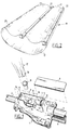
- Figure 1 shows a cable sleeve 1 which serves for mutual connection of cables 2, 3, 4.
- a tray 5 which can be closed by a cover 6.
- the bottom of tray 5 is formed by a transparent plate 7 with a hole 8 serving as filling opening.
- the bottom 7 is supported by two ribs 9, 10 formed in the sleeve 1.
- the bottom 7 has two upward sloping ends 11, 12 whereby in this embodiment it is arranged lightly clamping in the tray 5.
- a venting opening 13 connects under the level of the top edge 14 of the tray via a venting channel to the cavity 15 enclosed by the cable sleeve 1.
- a carbon filter located in the venting channel whereby during the filling of the cavity 15 to be described below no harmful vapours can escape.
- Figure 1 further shows an end 16 of a filling tube 17 to be described hereinafter which can be sealingly and clampingly coupled by means of a hollow, conical wedge piece 18 to the filling opening 8. This aspect will be discussed further with reference to figure 6.
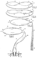
- Figure 2 shows a flexible packaging 19 in the form of an annular plastic tube comprising a transverse seal seam 20 in addition to two metal clamps 21, 22.
- the seal seam 20 and the metal clamp 21 form the dividers bounding a first compartment 23.
- the clamps 21 and 22 bound a second compartment 24 in analogous manner.
- the compartments 23 and 24 contain the two components which are mixed with one another at a later stage, whereafter the formed mixture has to be carried into the cable sleeve 1.
- the metal clamp 22 bounds with the seal seam 20 an empty part of the packaging which will later serve as filling tube.
- Figure 3 shows the packaging 19 in its original form. It will be apparent that the packaging 19 has the form of a closed loop or ring. As a result it can be very easily carried and handled by a user.
- Figure 4 shows a following phase wherein the clamp 21, which formed the division between the compartments 23 and 24, is removed.
- the compartments 23 and 24 thereby come into open communication with one another, whereby the user has the opportunity to mix together the two components present therein by kneading the packaging 19.
- Figure 5 shows, likewise schematically, the final form wherein the compartments 23, 24 form one entity and contain the homogeneous mixture.
- the filling tube 17 is also brought in its final form by cutting it through in the vicinity of the seal seam 17.
- the free end 16 of the filling tube is thereby made available as according to figure 1.
- Figure 6 shows that the conical wedge piece is arranged in the end 16 of the filler tube 17. This takes place prior to the removal of the metal clamp 22, therefore with the filling tube 17 in "clean" state.
- the end 16 of the filling tube is inserted clampingly into the filling opening 8 making use of the wedge piece 18 such that by squeezing out packaging 19 according to arrows 25 the mixture can be admitted as according to arrow 26 via the filling tube 17 into the cavity 15.
- Figure 7 shows the assembled cable sleeve 1 filled with mixture 27.
- the whole packaging 19 after having been at least substantially emptied, is laid on the bottom 7 without breaking the coupling by means of the wedge piece 8, whereafter the tray 5 is closed by the cover 6.
- the last phase in the assembly of the cable sleeve 1 is thereby completed.
- figure 8 shows a mixing device 28 wherein a packaging is placed in the phase of figure 4.
- the device 28 comprises an unprofiled press roller 29 and, spring-loaded towards it, a profiled press roller 30 which is drivable by a handle 31.
- This wringer construction serves for mixing of the two components in the compartments 23 and 24 during wringing. Due to the closed loop form of the packaging 19 the action of the device 28 can take place continuously. To this end the packaging is guided over a reversing roller 32.
- Pressing out of the packaging in the situation of figure 6 can be carried out manually without extra tools; in order to ensure the fullest possible emptying of the packaging, however, squeezing out the compartment 23, 24 by winding up in the per se known manner of a tube by means of a rotatable clamp could also be used.
Landscapes
- Engineering & Computer Science (AREA)
- General Engineering & Computer Science (AREA)
- Mechanical Engineering (AREA)
- Basic Packing Technique (AREA)
- Packaging Of Annular Or Rod-Shaped Articles, Wearing Apparel, Cassettes, Or The Like (AREA)
- Processing Of Terminals (AREA)
Claims (8)
- Vorrichtung zum Auffüllen eines von einem Gehäuse umschlossenen Hohlraums, beispielsweise einer Kabelmuffe, mit einem Gemisch aus zwei Komponenten, wobei das Gehäuse eine Einfüllöffnung aufweist, um das Gemisch in dem Hohlraum plazieren zu können, wobei die Vorrichtung ein hohles Konuskeilstück (8) und eine flexible Packung (19) aufweist, welche mit drei Kammern (17, 23, 24) versehen ist, welche von zwei entfernbaren Trenneinrichtungen (21, 22) voneinander separiert sind, wobei zwei der Kammern (23, 24) aneinander angrenzen und die beiden jeweiligen Komponenten aufweisen und die dritte Kammer als ein Einfüllrohr (17) zum Einsetzen in die Einfüllöffnung dient,
wobei die beiden Kammern (23, 24), welche die Komponenten beinhalten, in offener Verbindung miteinander durch Entfernen der ersten Trenneinrichtung (21) gebracht werden können, wonach mittels Durchkneten der Packung die Komponenten ein einheitliches Gemisch ausbilden können,
das Einfüllrohr (17) in die Einfüllöffnung einsetzbar ist, und
die zweite Trenneinrichtung (22) entfernbar ist, so daß das Gemisch in den Hohlraum durch das Einfüllrohr (17) hindurch mittels Herauspressen aus der Packung einfüllbar ist, wobei
die entfernbaren Trenneinrichtungen (21, 22) als zwei elastisch gegeneinander pressende Streifen ausgebildet sind, welche beispielsweise nach Art einer Haarklammer die Packung zusammenpressen, und wobei das hohle Konuskeilstück das Ende (16) des Einfüllrohrs mit der Kante der Einfüllöffnung verbindet, wobei das hohle Konuskeilstück in das Ende (16) einsetzbar ist und dieses Ende (16) in die Einfüllöffnung an einer der Stellung des Konuskeilstücks (9) entsprechenden Stelle einsetzbar ist, wodurch so das Ende des Einfüllrohrs (16) festgeklemmt wird. - Vorrichtung nach Anspruch 1, dadurch gekennzeichnet, daß ein Gehäuse mit einer Einfüllöffnung (8), um welche sich eine aufrechtstehende Wand erstreckt, einen Aufnahmekasten (5) ausbildet, auf welchem ein Schließdeckel (6) plaziert werden kann.
- Vorrichtung nach Anspruch 4, dadurch gekennzeichnet, daß eine Ventilationsöffnung (13) in der Nähe der Einfüllöffnung in dem Gehäuse (8) angeordnet ist und einen darin angeordneten Filter aufweist, um schädliche Abgase zu absorbieren, welche aus dem Gemisch entweichen.
- Vorrichtung nach Anspruch 5, dadurch gekennzeichnet, daß die Ventilationsöffnung (13) unterhalb der Oberkante des Aufnahmekastens (5) angeordnet ist.
- Vorrichtung nach Anspruch 4, dadurch gekennzeichnet, daß ein transparenter Wandteil (7) des Gehäuses in der Nähe der Einfüllöffnung (8) angeordnet ist.
- Vorrichtung nach Anspruch 1, gekennzeichnet durch einen antreibbaren Wringer (28) mit miteinander zusammenwirkenden Druckwalzen (29, 30), wovon zumindest eine mit einem Profil versehen ist, wobei der Wringer zum Durchkneten der Packung dient.
- Vorrichtung nach Anspruch 1, dadurch gekennzeichnet, daß die Packung (19) ringförmig ist und die Trenneinrichtungen (21, 22) sich mehr oder weniger in Querrichtung dazu erstrecken, wobei das Einfüllrohr (17) von den ersten beiden Kammern auf der einen Seite durch die zweite entfernbare Trenneinrichtung (22) und auf der anderen Seite durch eine dritte Trenneinrichtung (20) separiert ist, und durchgeschnitten werden kann, um so das Ende des Einfüllrohrs auszubilden.
- Vorrichtung nach Ansprüchen 8 und 9, gekennzeichnet durch eine Umlenkwalze (32), über welche die Packung zurück zu dem Wringer geführt werden kann, nachdem sie diesen verlassen hat.
Applications Claiming Priority (2)
| Application Number | Priority Date | Filing Date | Title |
|---|---|---|---|
| NL8903118 | 1989-12-20 | ||
| NL8903118A NL8903118A (nl) | 1989-12-20 | 1989-12-20 | Systeem voor het vullen van een holte. |
Publications (2)
| Publication Number | Publication Date |
|---|---|
| EP0434105A1 EP0434105A1 (de) | 1991-06-26 |
| EP0434105B1 true EP0434105B1 (de) | 1994-10-12 |
Family
ID=19855811
Family Applications (1)
| Application Number | Title | Priority Date | Filing Date |
|---|---|---|---|
| EP90203025A Expired - Lifetime EP0434105B1 (de) | 1989-12-20 | 1990-11-14 | Vorrichtung zum Füllen eines Hohlraumes |
Country Status (6)
| Country | Link |
|---|---|
| EP (1) | EP0434105B1 (de) |
| AT (1) | ATE112747T1 (de) |
| DE (1) | DE69013307T2 (de) |
| DK (1) | DK0434105T3 (de) |
| ES (1) | ES2060935T3 (de) |
| NL (1) | NL8903118A (de) |
Families Citing this family (7)
| Publication number | Priority date | Publication date | Assignee | Title |
|---|---|---|---|---|
| WO1996012660A1 (en) * | 1994-10-19 | 1996-05-02 | Deltagraph A/S | A package and a method of packaging at least two mutually reactive photographic chemicals |
| US5951160A (en) * | 1997-11-20 | 1999-09-14 | Biomet, Inc. | Method and apparatus for packaging, mixing and delivering bone cement |
| FR2780661B1 (fr) * | 1998-07-02 | 2001-01-19 | App Mat Elect Const | Melangeur pret a l'emploi, notamment pour le remplissage des boites de derivation des reseaux electriques basse tension souterrains |
| AU2014274614B2 (en) * | 2009-08-21 | 2016-05-19 | Cmp Products Limited | Filler assembly for cable gland |
| EP2287986B1 (de) | 2009-08-21 | 2015-02-11 | CMP Products Limited | Fülleranordnung für einen Kabelstopfen |
| GB2485114B (en) * | 2009-08-21 | 2013-10-30 | Cmp Products Ltd | Filler assembly for cable gland |
| US10193321B2 (en) | 2009-08-21 | 2019-01-29 | Cmp Products Limited | Filler assembly for cable gland |
Family Cites Families (4)
| Publication number | Priority date | Publication date | Assignee | Title |
|---|---|---|---|---|
| BE815251A (fr) * | 1974-05-20 | 1974-11-20 | Cogebi Sa | Procede d'enrobage. |
| US3992569A (en) * | 1975-02-11 | 1976-11-16 | Hexcel Corporation | Protective cable enclosure, cable assembly including the same, and method of encapsulating a cable in a protective enclosure |
| DE3229595A1 (de) * | 1982-08-09 | 1984-02-09 | Basf Farben + Fasern Ag, 2000 Hamburg | Kabelmuffe |
| SE8306400L (sv) * | 1983-01-24 | 1984-07-25 | Bard Inc C R | Blandningsforpackning med ett flertal fack |
-
1989
- 1989-12-20 NL NL8903118A patent/NL8903118A/nl not_active Application Discontinuation
-
1990
- 1990-11-14 EP EP90203025A patent/EP0434105B1/de not_active Expired - Lifetime
- 1990-11-14 DE DE69013307T patent/DE69013307T2/de not_active Expired - Fee Related
- 1990-11-14 AT AT90203025T patent/ATE112747T1/de not_active IP Right Cessation
- 1990-11-14 ES ES90203025T patent/ES2060935T3/es not_active Expired - Lifetime
- 1990-11-14 DK DK90203025.3T patent/DK0434105T3/da active
Also Published As
| Publication number | Publication date |
|---|---|
| DE69013307D1 (de) | 1994-11-17 |
| DK0434105T3 (da) | 1995-02-27 |
| DE69013307T2 (de) | 1995-02-16 |
| ES2060935T3 (es) | 1994-12-01 |
| ATE112747T1 (de) | 1994-10-15 |
| NL8903118A (nl) | 1991-07-16 |
| EP0434105A1 (de) | 1991-06-26 |
Similar Documents
| Publication | Publication Date | Title |
|---|---|---|
| US5890781A (en) | Glove box | |
| US4294379A (en) | Upward vented trash receptacle for flexible collapsible trash liner | |
| US4950083A (en) | Packaging for a liquid composition which is ready for use, produced from a concentrated liquid composition, and method for its implementation | |
| FI68382C (fi) | Tvao- eller flerkomponentfoerpackning | |
| US4343978A (en) | Structure for use in microwave cooking | |
| US4898304A (en) | Viscous liquid dispenser | |
| GR850901B (de) | ||
| EP0434105A1 (de) | Vorrichtung zum Füllen eines Hohlraumes | |
| GB2039471B (en) | Apparatus for storing and stirring viscous liquids contained in cans | |
| JP2865649B2 (ja) | 液状または半液状製品の包装装置 | |
| DE3166399D1 (en) | Device for mixing a liquid contained in a test tube | |
| EP0382691A1 (de) | Behältnis für einen Reinigungs-Mop | |
| CA1124687A (en) | Liquid containing and dispensing device | |
| US4116354A (en) | Two chambered mixing container | |
| US3228444A (en) | Specimen container | |
| ES8204638A1 (es) | Dispositivo para el mezclado y desgasificacion de componen- tes de resinas sinteticas,especialmente de resinas artifi- ciales duroplasticas | |
| EP0429432A2 (de) | Behälter für Flüssigkeiten | |
| US5482177A (en) | Closure on a cartridge | |
| US4179042A (en) | Sealed dispenser spout assembly | |
| DE2901952A1 (de) | Zweikammerkanister | |
| EP0878402B1 (de) | Vorrichtung zum Entleeren von Pulver aus einem Sack | |
| JP4128499B2 (ja) | パッケージとパッケージを計量分配するための装置を含むアッセンブリおよびパッケージを計量分配するための装置 | |
| EP0874770B1 (de) | Verfahren und vorrichtung zum verpacken von gefriergut, zu entsorgendem gut wie beispielsweise hausmüll u. dgl. | |
| EP0619396A1 (de) | Dosierspender für Pulverwaschmittel zum Ablegen im Innern der Waschmaschinen | |
| WO1988005026A1 (en) | Dispenser for liquids contained in packages |
Legal Events
| Date | Code | Title | Description |
|---|---|---|---|
| PUAI | Public reference made under article 153(3) epc to a published international application that has entered the european phase |
Free format text: ORIGINAL CODE: 0009012 |
|
| AK | Designated contracting states |
Kind code of ref document: A1 Designated state(s): AT BE CH DE DK ES FR GB GR IT LI LU NL SE |
|
| 17P | Request for examination filed |
Effective date: 19911224 |
|
| 17Q | First examination report despatched |
Effective date: 19930519 |
|
| ITF | It: translation for a ep patent filed | ||
| GRAA | (expected) grant |
Free format text: ORIGINAL CODE: 0009210 |
|
| AK | Designated contracting states |
Kind code of ref document: B1 Designated state(s): AT BE CH DE DK ES FR GB GR IT LI LU NL SE |
|
| REF | Corresponds to: |
Ref document number: 112747 Country of ref document: AT Date of ref document: 19941015 Kind code of ref document: T |
|
| REF | Corresponds to: |
Ref document number: 69013307 Country of ref document: DE Date of ref document: 19941117 |
|
| REG | Reference to a national code |
Ref country code: ES Ref legal event code: FG2A Ref document number: 2060935 Country of ref document: ES Kind code of ref document: T3 |
|
| ET | Fr: translation filed | ||
| EAL | Se: european patent in force in sweden |
Ref document number: 90203025.3 |
|
| REG | Reference to a national code |
Ref country code: DK Ref legal event code: T3 |
|
| REG | Reference to a national code |
Ref country code: GR Ref legal event code: FG4A Free format text: 3014290 |
|
| PLBE | No opposition filed within time limit |
Free format text: ORIGINAL CODE: 0009261 |
|
| STAA | Information on the status of an ep patent application or granted ep patent |
Free format text: STATUS: NO OPPOSITION FILED WITHIN TIME LIMIT |
|
| 26N | No opposition filed | ||
| PGFP | Annual fee paid to national office [announced via postgrant information from national office to epo] |
Ref country code: GB Payment date: 20001030 Year of fee payment: 11 |
|
| PGFP | Annual fee paid to national office [announced via postgrant information from national office to epo] |
Ref country code: LU Payment date: 20001129 Year of fee payment: 11 Ref country code: BE Payment date: 20001129 Year of fee payment: 11 Ref country code: AT Payment date: 20001129 Year of fee payment: 11 |
|
| PGFP | Annual fee paid to national office [announced via postgrant information from national office to epo] |
Ref country code: SE Payment date: 20001130 Year of fee payment: 11 Ref country code: NL Payment date: 20001130 Year of fee payment: 11 Ref country code: GR Payment date: 20001130 Year of fee payment: 11 Ref country code: FR Payment date: 20001130 Year of fee payment: 11 Ref country code: ES Payment date: 20001130 Year of fee payment: 11 Ref country code: DK Payment date: 20001130 Year of fee payment: 11 Ref country code: DE Payment date: 20001130 Year of fee payment: 11 |
|
| PGFP | Annual fee paid to national office [announced via postgrant information from national office to epo] |
Ref country code: CH Payment date: 20001205 Year of fee payment: 11 |
|
| PG25 | Lapsed in a contracting state [announced via postgrant information from national office to epo] |
Ref country code: LU Free format text: LAPSE BECAUSE OF NON-PAYMENT OF DUE FEES Effective date: 20011114 Ref country code: GB Free format text: LAPSE BECAUSE OF NON-PAYMENT OF DUE FEES Effective date: 20011114 Ref country code: DK Free format text: LAPSE BECAUSE OF NON-PAYMENT OF DUE FEES Effective date: 20011114 Ref country code: AT Free format text: LAPSE BECAUSE OF NON-PAYMENT OF DUE FEES Effective date: 20011114 |
|
| PG25 | Lapsed in a contracting state [announced via postgrant information from national office to epo] |
Ref country code: SE Free format text: LAPSE BECAUSE OF NON-PAYMENT OF DUE FEES Effective date: 20011115 Ref country code: ES Free format text: LAPSE BECAUSE OF NON-PAYMENT OF DUE FEES Effective date: 20011115 |
|
| PG25 | Lapsed in a contracting state [announced via postgrant information from national office to epo] |
Ref country code: LI Free format text: LAPSE BECAUSE OF NON-PAYMENT OF DUE FEES Effective date: 20011130 Ref country code: GR Free format text: LAPSE BECAUSE OF NON-PAYMENT OF DUE FEES Effective date: 20011130 Ref country code: CH Free format text: LAPSE BECAUSE OF NON-PAYMENT OF DUE FEES Effective date: 20011130 Ref country code: BE Free format text: LAPSE BECAUSE OF NON-PAYMENT OF DUE FEES Effective date: 20011130 |
|
| REG | Reference to a national code |
Ref country code: GB Ref legal event code: IF02 |
|
| BERE | Be: lapsed |
Owner name: LOVINK TERBORG B.V. Effective date: 20011130 |
|
| PG25 | Lapsed in a contracting state [announced via postgrant information from national office to epo] |
Ref country code: NL Free format text: LAPSE BECAUSE OF NON-PAYMENT OF DUE FEES Effective date: 20020601 |
|
| EUG | Se: european patent has lapsed |
Ref document number: 90203025.3 |
|
| PG25 | Lapsed in a contracting state [announced via postgrant information from national office to epo] |
Ref country code: DE Free format text: LAPSE BECAUSE OF NON-PAYMENT OF DUE FEES Effective date: 20020702 |
|
| REG | Reference to a national code |
Ref country code: CH Ref legal event code: PL Ref country code: DK Ref legal event code: EBP |
|
| PG25 | Lapsed in a contracting state [announced via postgrant information from national office to epo] |
Ref country code: FR Free format text: LAPSE BECAUSE OF NON-PAYMENT OF DUE FEES Effective date: 20020730 |
|
| NLV4 | Nl: lapsed or anulled due to non-payment of the annual fee |
Effective date: 20020601 |
|
| REG | Reference to a national code |
Ref country code: FR Ref legal event code: ST |
|
| REG | Reference to a national code |
Ref country code: FR Ref legal event code: ST |
|
| REG | Reference to a national code |
Ref country code: ES Ref legal event code: FD2A Effective date: 20021213 |
|
| PG25 | Lapsed in a contracting state [announced via postgrant information from national office to epo] |
Ref country code: IT Free format text: LAPSE BECAUSE OF NON-PAYMENT OF DUE FEES Effective date: 20051114 |