EP0434129A2 - Tordeur pour une machine textile permettant le bobinage de bobines parfaitement cylindrique - Google Patents
Tordeur pour une machine textile permettant le bobinage de bobines parfaitement cylindrique Download PDFInfo
- Publication number
- EP0434129A2 EP0434129A2 EP90203276A EP90203276A EP0434129A2 EP 0434129 A2 EP0434129 A2 EP 0434129A2 EP 90203276 A EP90203276 A EP 90203276A EP 90203276 A EP90203276 A EP 90203276A EP 0434129 A2 EP0434129 A2 EP 0434129A2
- Authority
- EP
- European Patent Office
- Prior art keywords
- bobbin
- trumpet
- rotation
- twister
- rotary
- Prior art date
- Legal status (The legal status is an assumption and is not a legal conclusion. Google has not performed a legal analysis and makes no representation as to the accuracy of the status listed.)
- Withdrawn
Links
Images


Classifications
-
- D—TEXTILES; PAPER
- D01—NATURAL OR MAN-MADE THREADS OR FIBRES; SPINNING
- D01H—SPINNING OR TWISTING
- D01H13/00—Other common constructional features, details or accessories
- D01H13/04—Guides for slivers, rovings, or yarns; Smoothing dies
-
- D—TEXTILES; PAPER
- D01—NATURAL OR MAN-MADE THREADS OR FIBRES; SPINNING
- D01H—SPINNING OR TWISTING
- D01H13/00—Other common constructional features, details or accessories
- D01H13/04—Guides for slivers, rovings, or yarns; Smoothing dies
- D01H13/06—Traversing arrangements
-
- D—TEXTILES; PAPER
- D01—NATURAL OR MAN-MADE THREADS OR FIBRES; SPINNING
- D01H—SPINNING OR TWISTING
- D01H7/00—Spinning or twisting arrangements
- D01H7/92—Spinning or twisting arrangements for imparting transient twist, i.e. false twist
Definitions
- This invention relates to an improved twister device for a winding carriage, which enables the sliver leaving the gill box to be collected onto a bobbin which forms with perfect cylindrical geometry.
- sliver is used to indicate a textile fibre roving, a textile fibre sliver or any other textile fibre aggregate.
- the "false twist” is imparted to give the sliver the necessary roundness and strength so that its subsequent unwinding can take place without difficulty and without breakage.
- Rotary funnel twister and condenser devices are normally used in textile machines such as gill boxes to condense or compact a sliver in the form of loose textile fibres before its positioning and collection in helix form on the circumferential surface of the bobbin under formation.
- the sliver fed into the trumpet is substantially without twist, and when this sliver passes through the trumpet false twist device it is twisted about itself to assume compactness and a reduction in its transverse dimension, so reducing its volume in that the retained air is eliminated and the individual fibres are twisted together. It is apparent that the twist imparted upstream is nullified by the twist imparted downstream, as the trumpet acts as a false twist element.
- the trumpet is constructed and operated in the manner traditional in the art, it consisting essentially of a funnel rotating about its axis while being simultaneously subjected to axial to-and-fro movement along a path equal in length to the length of the desired bobbin.
- the funnel reverses its direction of rotation at the ends of the bobbin under formation, it rotating reciprocatingly in the two directions according to its direction of linear movement.
- This rotation in the two directions is induced by the rolling of a pulley associated with the rotary funnel along a fixed flat element, as is well known in the art in terms of the methods used up to the present time.
- the invention proposes an improved twister device for a winding carriage collecting the sliver emerging from the gill box, which is able to wind bobbins in perfect cylindrical form using drive means which rotate the rotary trumpet independently of its to-and-fro linear movement, for the purpose of reversing the rotation substantially at the middle of the bobbin under formation.
- Said drive means comprise components which receive rotation from the drive shaft, to operate a crank-connecting rod mechanism arranged to angularly reciprocate a toothed sector, this latter engaging a toothed pinion to transmit reciprocating rotary motion in the two directions, via a linkage comprising pulleys, belts and cables, to the trumpet, which then imparts the false twist to the sliver an instant before this latter is deposited as a crossed winding on the circumferential surface of the bobbin under formation.
- the improved twister device for a winding carriage comprises drive means which impress on the rotary funnel-type trumpet reciprocating rotations with rotation reversal at points on the transverse path of the trumpet which do not coincide with the two ends of the bobbin under formation, this being possible by suitably positioning between them the components of said drive means.
- the device according to the invention therefore allows the rotation reversal points of the trumpet to be chosen within any part of the transverse path which does not coincide with the ends of the bobbin under formation, and thus achieve improved binding of the various layers in which the sliver is collected, to consequently allow the subsequent unwinding to take place without any abnormal tension and thus without breakage of the sliver.
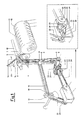
- Figure 1 is an axonometric perspective schematic view of the device of the present invention showing the entire motion transmission, together with a detailed view of the drive means for the toothed sector, which is advantageously disposed in a gearbox;
- Figure 2 shows the linkage scheme for the operating elements within the toothed sector gearbox, and represents the motion configuration at the instant in which the toothed sector reverses its angular rotation;
- Figure 2a is a schematic view of the rotary funnel-type trumpet of the mobile twister unit in a middle position on the bobbin under formation, in said middle position the trumpet reversing its direction of rotation at the instant corresponding to the reversal of the angular rotation of the toothed sector, as shown in the linkage scheme of Figure 2;
- Figure 3 shows the linkage scheme for the operating elements within the tooth
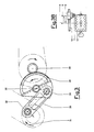
- FIG. 6 is a schematic view of the rotary funnel-type trumpet of the mobile twister unit at any point between the midpoint and one end of the surface of the bobbin under formation. At said point the trumpet reverses its direction of rotation.
- the figure represents the instant in which the trumpet is not rotating, as it is in the process of passing from one direction of rotation to the opposite direction of rotation.
- 1 is the drive shaft which rotates with constant rotation to transversely drive the mobile twister unit 8 and rotate the twister device of the present invention
- 3 is a belt, cord or any flexible element transmitting rotary motion from the transmission pulley 2 to the pulley 5 via the idle deviation pulleys 4.
- the pulley 2 is rigid with the shaft 9 and the pulley 5 is rigid and integral with the trumpet 7 of the mobile twister unit 8
- 6 is the rocker arm or bar pivoted about the shaft 9, this being mobile to enable the unit 8 to travel with sliding to-and-fro movement along the guide shaft 10, in the direction of the arrows 14.
- Said arm 6 rocks angularly by the action of the connecting rod 18 which is connected to it by a connection member 16.
- Said connecting rod 18 is driven by the crank 21 via the connection pin 19, the crank 21 being rotated by the drive shaft 1 on which it is rigidly fixed;
- 11 is the drive roller for the bobbin 12 under formation, on which the fibre sliver 25 is wound;
- 15 is a spiral in the form of a helical spring within which the fibre sliver slides before entering the rotary trumpet 7.
- Said spiral 15, rigidly fixed to the unit 8 helps to compact the sliver 25, as is well known in the art; 22 are flexible belts or similar elements, advantageously toothed, to transmit motion via the toothed wheels 24, without the minimum slippage.
- the motor driving the drive shaft 1 which rotates constantly in the same direction is not shown.
- Said shaft 1 simultaneously drives the crank 21 and the toothed belt 22.
- This latter generates, via the toothed wheel 24,the crank 30 and the connecting rod 33, an angular reciprocating movement of the toothed sector 36, which engages the pinion 39 to transmit reciprocating rotary movement in the two directions to the trumpet 7 of the mobile unit 8 via the linkage formed by the pulleys 24 and 23, the belts 22 and the belt 3.
- the mobile unit 8 slides linearly along the guide shaft 10 with a to-and-fro movement through a distance substantially equal to the axial dimension of the bobbin 12 under formation.
- Said to-and-fro linear movement is generated by said crank 21 which drives the connecting rod 18 and hence the arm 6, which rocks about the shaft 9 to cause the twister unit 8 to move with a linear to-and-fro movement in accordance with the arrows 14.
- This latter linkage represents a well known application in the case of a gill box winding carriage.
- the toothed sector 36 has rotated through substantially one half of its angular travel and the rotary trumpet 7 has moved from the middle A to the end B of the bobbin 12. During said movement it rotates about itself with clockwise rotation, as can be seen from Figure 3B. From the position shown in Figure 3 the linkage moves into the position shown in Figure 4 under the continuous action of the crank 30.
Landscapes
- Engineering & Computer Science (AREA)
- Mechanical Engineering (AREA)
- Textile Engineering (AREA)
- Spinning Or Twisting Of Yarns (AREA)
Applications Claiming Priority (2)
| Application Number | Priority Date | Filing Date | Title |
|---|---|---|---|
| IT02278689A IT1237922B (it) | 1989-12-21 | 1989-12-21 | Dispositivo torsionatore perfezionato per carro bobinatore che permette di formare una bobina di perfetta forma cilindrica |
| IT2278689 | 1989-12-21 |
Publications (2)
| Publication Number | Publication Date |
|---|---|
| EP0434129A2 true EP0434129A2 (fr) | 1991-06-26 |
| EP0434129A3 EP0434129A3 (en) | 1991-09-18 |
Family
ID=11200443
Family Applications (1)
| Application Number | Title | Priority Date | Filing Date |
|---|---|---|---|
| EP19900203276 Withdrawn EP0434129A3 (en) | 1989-12-21 | 1990-12-12 | Improved twister device for a winding carriage enabling a bobbin of perfectly cylindrical shape to be formed |
Country Status (2)
| Country | Link |
|---|---|
| EP (1) | EP0434129A3 (fr) |
| IT (1) | IT1237922B (fr) |
Cited By (2)
| Publication number | Priority date | Publication date | Assignee | Title |
|---|---|---|---|---|
| US5524841A (en) * | 1994-05-26 | 1996-06-11 | Ppg Industries, Inc. | Apparatus and methods for winding a plurality of strands |
| CN107385577A (zh) * | 2017-08-22 | 2017-11-24 | 安徽佳元工业纤维有限公司 | 一种倍捻机上实现多股线初捻差异化的方法 |
Family Cites Families (6)
| Publication number | Priority date | Publication date | Assignee | Title |
|---|---|---|---|---|
| US2674013A (en) * | 1950-01-21 | 1954-04-06 | Barre Wool Combing Company Ltd | Sliver feed mechanism |
| US2757876A (en) * | 1952-05-16 | 1956-08-07 | Warner Swasey Co | Undershot baller |
| GB1111129A (en) * | 1964-07-10 | 1968-04-24 | Mackie & Sons Ltd J | Improvements in winding apparatus |
| DE1629309C2 (de) * | 1966-11-09 | 1973-01-04 | Josef Baer Maschinenfabrik, 7987 Weingarten | Antriebssystem für Wickelmaschinen |
| DE1560584A1 (de) * | 1966-12-03 | 1971-02-11 | Reiners Walter Dr Ing | Spulmaschine mit hin- und hergehendem Fadenfuehrer |
| IT1205058B (it) * | 1987-06-19 | 1989-03-10 | Savio Spa | Dispositivo torsionatore per carro bobinatore |
-
1989
- 1989-12-21 IT IT02278689A patent/IT1237922B/it active IP Right Grant
-
1990
- 1990-12-12 EP EP19900203276 patent/EP0434129A3/en not_active Withdrawn
Cited By (2)
| Publication number | Priority date | Publication date | Assignee | Title |
|---|---|---|---|---|
| US5524841A (en) * | 1994-05-26 | 1996-06-11 | Ppg Industries, Inc. | Apparatus and methods for winding a plurality of strands |
| CN107385577A (zh) * | 2017-08-22 | 2017-11-24 | 安徽佳元工业纤维有限公司 | 一种倍捻机上实现多股线初捻差异化的方法 |
Also Published As
| Publication number | Publication date |
|---|---|
| IT8922786A1 (it) | 1991-06-21 |
| IT8922786A0 (it) | 1989-12-21 |
| EP0434129A3 (en) | 1991-09-18 |
| IT1237922B (it) | 1993-06-18 |
Similar Documents
| Publication | Publication Date | Title |
|---|---|---|
| US4505436A (en) | Yarn winding apparatus | |
| KR101760905B1 (ko) | 로프 제조기 | |
| US2262589A (en) | Textile manufacture | |
| EP0434129A2 (fr) | Tordeur pour une machine textile permettant le bobinage de bobines parfaitement cylindrique | |
| US4085903A (en) | Yarn winding apparatus | |
| GB1116476A (en) | Method and apparatus for winding roving | |
| EP0435366A2 (fr) | Tordeur pour une machine textile permettant le bobinage de bobines compactes | |
| US4819422A (en) | Arrangement for winding a double yarn onto a cross-wound spool | |
| EP1473388A2 (fr) | Dispositif de condensation pour des machines à filer | |
| US4007611A (en) | Yarn and method knitting same | |
| GB553834A (en) | Improvements in yarn and like winding machines | |
| JP3094370B2 (ja) | 巻取機のトラバース装置 | |
| US3748874A (en) | Yarn knitting machine | |
| CN219586282U (zh) | 帘子线捻线制样机 | |
| EP0643160A1 (fr) | Dispositif à rouleau pour régler l'inégalité d'un ruban dans une machine de cardage | |
| US2181267A (en) | Reciprocating guide head for yarn packaging device | |
| US2834178A (en) | Strand handling machine | |
| US2968446A (en) | Baller head | |
| US2650414A (en) | Control device | |
| EP0295731B1 (fr) | Dispositif pour produire une fausse torsion à un ruban de fibres textiles | |
| US2996870A (en) | Winding tension control mechanism | |
| US2964898A (en) | Cross winding apparatus for textile drawing frames | |
| US2914904A (en) | Cord twister and winder | |
| EP0295733A1 (fr) | Guide en spirale pour fils textiles pour compenser une torsion à l'envers | |
| CN220977268U (zh) | 一种导纱机构及细纱机 |
Legal Events
| Date | Code | Title | Description |
|---|---|---|---|
| PUAI | Public reference made under article 153(3) epc to a published international application that has entered the european phase |
Free format text: ORIGINAL CODE: 0009012 |
|
| AK | Designated contracting states |
Kind code of ref document: A2 Designated state(s): BE CH DE ES FR GB GR LI |
|
| PUAL | Search report despatched |
Free format text: ORIGINAL CODE: 0009013 |
|
| AK | Designated contracting states |
Kind code of ref document: A3 Designated state(s): BE CH DE ES FR GB GR LI |
|
| 17P | Request for examination filed |
Effective date: 19911030 |
|
| 17Q | First examination report despatched |
Effective date: 19930727 |
|
| STAA | Information on the status of an ep patent application or granted ep patent |
Free format text: STATUS: THE APPLICATION IS DEEMED TO BE WITHDRAWN |
|
| 18D | Application deemed to be withdrawn |
Effective date: 19931207 |