EP0434158A2 - Verfahren zum Betrieb einer Datenverarbeitungsanlage und Datenverarbeitungsanlagen - Google Patents
Verfahren zum Betrieb einer Datenverarbeitungsanlage und Datenverarbeitungsanlagen Download PDFInfo
- Publication number
- EP0434158A2 EP0434158A2 EP90203355A EP90203355A EP0434158A2 EP 0434158 A2 EP0434158 A2 EP 0434158A2 EP 90203355 A EP90203355 A EP 90203355A EP 90203355 A EP90203355 A EP 90203355A EP 0434158 A2 EP0434158 A2 EP 0434158A2
- Authority
- EP
- European Patent Office
- Prior art keywords
- processes
- application
- recording process
- data
- level
- Prior art date
- Legal status (The legal status is an assumption and is not a legal conclusion. Google has not performed a legal analysis and makes no representation as to the accuracy of the status listed.)
- Withdrawn
Links
Images
Classifications
-
- G—PHYSICS
- G06—COMPUTING OR CALCULATING; COUNTING
- G06F—ELECTRIC DIGITAL DATA PROCESSING
- G06F11/00—Error detection; Error correction; Monitoring
- G06F11/30—Monitoring
- G06F11/34—Recording or statistical evaluation of computer activity, e.g. of down time, of input/output operation ; Recording or statistical evaluation of user activity, e.g. usability assessment
- G06F11/3466—Performance evaluation by tracing or monitoring
- G06F11/3476—Data logging
Definitions
- the invention relates to a method of operating a data processing system to obtain information on the running of an application process by the system, the method comprising running the application process while periodically suspending the operation of the application process to run a recording process which stores data recording specific events or status information, wherein the application process is one of a group of concurrent application processes and the recording process comprises a first level recording process which runs for a short time relatively frequently to store data in an unprocessed form, and a second level recording process which runs for a longer time less frequently and which processes the data stored by the first level recording process.
- the invention further relates to a data processing system operating in accordance with such a method.
- the invention further relates in particular to a data processing system comprising a plurality of processing nodes, each node running at least one of a group of concurrent application processes, and an inter-node communication network to which the nodes are connected and which enables data to be exchanged between application processes of the group running on different nodes.
- a data processing system comprising a plurality of processing nodes, each node running at least one of a group of concurrent application processes, and an inter-node communication network to which the nodes are connected and which enables data to be exchanged between application processes of the group running on different nodes.
- DOOM a Decentralised object-oriented machine
- EP-A2-0316250 A method as set forth in the opening paragraph above is described in EP-A2-0316250, which aims to study workload distribution in a given configuration of processing hardware resources. Recording processes in general are widely used also where the application process is defined by software which is still under development by its designer. The designer is able to analyse the stored data during or after the running of the application process for example to check whether the process is operating as intended. The stored data may also for example reveal a "bottleneck" in the software or hardware defining the process where a slight re-design could greatly improve the overall performance.
- the recording process is divided into two (or more) levels, as described above.
- the first level performs only a data gathering function, with the shortest possible interruption, while the second level processs operates periodically to process the gathered data whereupon a volume of recorded data can be treated efficiently.
- resource utilisation data are gathered locally at a high frequency (corresponding to a first level process), and periodically "retrieved" (transferred to a host processor) (corresponding to a second level process).
- a low overhead is particularly desirable for example when the application process is required to interact with the other processes in the group, or to respond in real-time to external influences. In such a situation, realism can be seriously impaired if the same degree of recording processing overhead is not experienced by all of the application processes.
- Such concurrent processes may be running by time-sharing on a single processor, or by parallel processing in a multi-processor system such as that set forth in the second opening paragraph.
- EP-A2-0316250 does not describe the problem of unequal recording overhead in different processes, nor is there described any relationship between concurrent recording processes. In the embodiment of EP-A2-0316250 only one "workstation controller" is shown connected to the host computer, and the relationship between concurrent recording processes is not described for the case of a plurality of such controllers.
- EP-A1-0368190 published after the priority date of the present application
- EP-A2-0130467 but without multilevel recording and without reference to the problem of concurrent application processes suffering differing amounts of recording overhead.
- EP-A1-0368190 for example, the recorded data, being limited in volume, is simply stored and only processed off-line, when realism is no longer a concern.
- the invention provides in its first aspect a method as set forth in the opening paragraph, characterized in that all application processes in the group are suspended during the running of the second level recording process, but only the one application process is suspended during the running of the first level recording process.
- the other application processes of the group may all have corresponding recording processes if desired, each being operated at two levels in accordance with the invention or not.
- at least one further application process in the group is suspended to run a corresponding further recording process comprising further first and second level recording processes
- all application processes in the group are suspended to run the second level recording processes of more than one recording process and are resumed only after all the said second level recording processes have been run.
- the activation of a number of second level recording processes is synchronized, which may reduce the disruption of the application processes, for example if the second level recording processes can be run in parallel.
- the first mentioned recording process may emit a global interrupt signal to suspend all of the application processes in the group and (if desired) activate the or each further second level recording process.
- the one recording process may have been previously nominated as a "master" of the other processes.
- the interrupt signal may be generated by the first recording process to require activation at the second level, for example because a data buffer for that recording process is full.
- each second level recording process emits a ready signal upon completion and all application processes in the group are resumed when the last second level process to emit a ready signal has done so.
- the ready signal may take any form, from that of a simple binary signal on a wire to that of a predetermined software message.
- the second level recording process may act simply to compress the unprocessed data generated at the first level, and/or it may reduce memory overhead by transferring the data to a remote storage device where it cannot affect the realistic operation of the application process.
- the second level recording process may be activated, for example, upon the expiry of a pre-programmed timer or whenever the amount of unprocessed data stored exceeds a threshold level.
- the invention further provides a data processing system when operating to run a group of concurrent application processes and at least one recording process in accordance with a method embodying the invention as set forth above.
- a system may in some cases comprise a special-purpose development system including additional hardware features over the "target" system whose performance running the application process is being simulated.
- the invention still further provides a data processing system comprising a plurality of processing nodes, each node running at least one of a group of concurrent application processes, and an inter-node communication network to which the nodes are connected and which enables data to be exchanged between application processes of the group running on different nodes, characterized in that at least one node is running a second level recording process in accordance with the method of the invention as set forth above, and in that the system further comprises means distinct from the first mentioned inter-node communication network for communicating to all nodes the global interrupt signal generated by the recording process, and means within each node for causing synchronous interruption of processing on the node upon receipt of such a global interrupt signal.
- the at least one node in such a data processing system may comprise means for communicating a ready signal generated by the second level recording process, the system further comprising means for generating a resume signal when the or each second level recording process has generated a ready signal, and means for causing synchronized resumption of suspended processes on all nodes in response to the said resume signal.
- the global interrupt signal communication means incorporates a logic function and forms the means for generating the resume signal when all nodes have generated a ready signal.
- the said means may comprise a single conductor implementing for example a wired-OR function. However, a connection providing more complex serial or parallel data transfer between nodes and incorporating the desired logic function may be preferable, for example where there are a large number of nodes in the system.
- the synchronized resumption of interrupted processes may for example be effected by generating a further global interrupt signal.
- the system comprising a further inter-node communication network distinct from the first-mentioned inter-node communications network, by means of which the second level recording process or processes running on one or more of the nodes exchange data between nodes and/or with a further processing device.
- the further communication network may also perform other functions, for example so that programs and data may be downloaded to the data processing system from a host computer system.
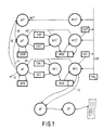
- Figure 1 shows schematically the relationship between an application process AP under development by a programmer and a two-level recording process in the form of a monitor process MP1/MP2 which is being run in this example to obtain statistical data for "profiling" the operation of the application process.
- the running of the process AP is supervised by the person developing the application via a host process HP which provides in a conventional manner development facilities such as editing, file serving, compiling, linking and so forth.
- An output process OP serves inter alia to display or print tables, graphs, charts, and so forth using the monitor data gathered by the monitor process MP1/MP2.
- the principle of a multi-level recording process is not dependent on the hardware or software structure in any particular system.
- the different processes AP, MP1, MP2, HP and OP could all be run on the same central processor (CPU) or could be distributed over a variety of processors. Each process may itself be running on a conventional sequential CPU or on a distributed/parallel CPU.
- the application process AP and monitor process MP1/MP2 are shown connected by data paths to an application process memory APM and monitor data buffer MDB respectively.
- These memories APM and MDB, and also memories for the host process HP and the output process OP may be embodied in separate elements of the system hardware or in a common block of memory.
- process AP will interact with data in its memory APM, and perhaps with external factors (dotted data path 10) and other concurrent processes AP' and AP", as described below.
- the structure of the program defining process AP will of course vary, but elements of a typical program can be seen in Listing 1 below.
- the program in Listing 1 may be written in any suitable computer language and has been divided into a number of discrete functions.
- a function "main()" serves as the highest level entry point for the process, and lower level functions "f(%)", “g(%)", “h(%)", and “j(%)” define distinct procedures within the process.
- Each function can be called from within another function.
- function j(%) may be executed as part of function g(%) (see line 18) or function h(%) (line 24).
- These different types of events can be distinguished by reference to the calling (“father”) function and the called ("son") function. With recursive function calls (not illustrated), the father and son may be the same.
- the system operator may wish to obtain a statistical record of such "father-son” events.
- a known and convenient form for such monitor data is shown in Table 1.
- the first column consists of a list of event types (in this case different father-son pairs) and for each event type the second column contains a count of events of that event type.
- a "generate profile” program "gprof(%)" is known which can generate a display or printout from data collected in this form.
- the monitor process MP1/MP2 is provided to generate this data in the monitor data buffer MDB, which can be accessed by the host process HP and consequently the output process OP.
- An event detector ED1 monitors the progress of the application process AP and responds to the occurrence of every event of a type which it is desired to record.
- the event detector may be embodied in hardware or it may be a segment of code embedded in the application process program at a point appropriate to the event being recorded which activates the monitor process MP1/MP2.
- the dotted link INT indicates that the application process AP is suspended during operation of the monitor process MP1/MP2.
- the monitor process should interfere with the application process as little as possible, so that the operation of the system is a realistic simulation of the application process as it will finally operate. This is particularly the case in real-time computer systems and in cases where the application process interacts with concurrent processes (AP' and AP").
- the monitor process To update a statistical record such as that represented in Table 1 at each event the monitor process must first identify the event type and locate the entry for that type in the stored table and then read, increment and restore the event count stored in the table. In a typical computer system this may require for example 20-30 instructions to be executed to record each event. This amount of overhead has been accepted in the past as necessary in order to obtain the required data, but when, for example, the event being detected is a very frequent one, occurring perhaps every few hundred instructions, then this overhead can easily come to represent significant portion of processor time, and the simulation of the application process becomes less than realistic.
- the monitor process illustrated in Figure 1 comprises two separate processes MP1 and MP2. Only the first level process MP1 is activated by the event detector ED1 for each event, while the second level monitor process MP2 is activated by a timer TIM2 and runs much less frequently than the first level process MP1.
- the first level process MP1 merely records the events as they occur, without producing a statistical table or otherwise compressing the monitor data.
- the first level process MP1 generates a large volume of unprocessed monitor data in the monitor data buffer MDB in a form such as that illustrated by Table 2 below.
- Each entry in the Table 2 represents one event and contains two program counter values PCF and PCS identifying the father function and the son function for the event.
- mmmm represents the program counter value on entering function main, ffff that on entering function f and so on.
- each entry specifies the event type for a single recorded event. Counting the events of each type recorded in Table 2 will lead to the figures given in Table 1.
- the first level monitor process MP1 may typically require only 5 or 6 instructions, so that the application process AP can run more realistically.
- such a short routine can generally be in-line coded, whereas a larger routine would have to be provided as a subroutine.
- the additional overhead involved in subroutine calls can therefore be avoided.
- the second level process MP2 is provided because the volume of the monitor data in its unprocessed form (Table 2) can be very large, considering that certain events might occur hundreds of times every second.
- An additional factor is that the space for the monitor data buffer MDB may have been provided within the same physical memory as the application process memory APM. In that case, a large monitor data buffer might be unavailable, or might at least further reduce the realism of the simulation.
- the second level monitor process MP2 performs the processing required to convert the unprocessed monitor data (Table 2) into the more compact statistical form of Table 1 and stores it back in the monitor data buffer.
- the compact data can be read by the host process HP after the completion of the application process run.
- the second level monitor process might simply transfer the unprocessed data (Table 2) to a remote and more capacious memory store. In a system where the host process HP operates in a remote system with access to its own memory and mass storage, this alternative may be advantageous.
- the output process OP may also be enabled to provide a "live" display of the system performance as the monitor data is collected.
- a timer TIM1 may be provided in hardware or software form which can activate the first level monitor process independently of the event detector ED1.
- the first level monitor process MP1 may, for example, record in the monitor data buffer MDB status information such as that illustrated by Table 3. This type of recording, known as "sampling", provides a regular "snapshot" of the application process.
- Each sample in Table 3 includes (by way of example only) the current program counter value (PC) in the program defining the application process, a register value (REG1) and/or further data on the number of communication actions, the number of idle program loops and so forth.
- the sample data stored in the buffer MDB can also be compressed and/or transferred by the second level process MP2 far more efficiently than if it were compressed or transferred at every sample.
- Figure 1 shows two further application processes AP' and AP" which run concurrently with the first-mentioned application process AP.
- the processes AP, AP' and AP" may run on a common CPU by time-sharing or they may run in parallel on separate CPU's. They may use a common memory or have separate memories APM, APM' etcetera, as shown.
- the processes AP, AP' and AP" interact in some way via data paths 14, 15 and 16 so that any realistic simulation must involve running all three application processes.
- both processes AP and AP' are monitorable by corresponding monitor processes MP1/MP2 and MP1'/MP2'.
- the monitor process MP1'/MP2' corresponding to the second application process AP' has its own event detector ED1' and/or timer TIM1' for interrupting the process AP' (as indicated by the dotted lid INT') and activating the corresponding first level process MP1'.
- the second level processes MP2 and MP2' however are both activated by the same timer TIM2 whose output therefore carries a "global interrupt” signal GINT, rather than a "local” interrupt signal such as those generated by the timers TIM1 and TIM1'.
- a corresponding "empty" second level monitor process MP2" is provided as a synchronizing process for interrupting the third application process AP" (dotted link INT) in response to the global interrupt signal GINT.
- an event detector ED2 may be provided to generate the global interrupt signal GINT.
- the event detector ED2 might be sensitive for example to the amount of unprocessed monitor data in the buffer MDB.
- Another event detector ED2' could be sensitive in the same way to the amount of data in the buffer MDB' for the second process AP'.
- the global interrupt could be triggered as soon as any of the buffers MDB, MDB' becomes too full of unprocessed monitor data.
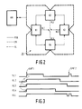
- FIG. 2 shows a parallel computer system 20 connected to a host computer HM.
- the parallel computer comprises four separate processing nodes N1, N2, N3 and N4.
- the nodes N1-N4 are arranged together in a ring network.
- Each node includes a data processor and also a communication processor to provide packet switching communication links PSN between neighbouring nodes in the ring.
- Each node N1-N4 is also connected to the host computer HM via an independent "ethernet"-type network EN.
- the host computer running a host process such as that referenced HP in Figure 1, uses the ethernet network EN to download programs and data defining the application processes.
- the application processes themselves communicate only via the packet switching network PSN.
- the processing nodes N1 to N4 are provided with a further connection in the form of a "hold line" HL for implementing the global interrupt function.
- the operation of the hold line HL is illustrated by the waveform diagram of Figure 3.
- Listings 2, 3 and 4 define in pseudo-code form routines which are executed at different stages in the operation to synchronize the second level monitor processes corresponding to all application processes, even when these are distributed over different processing nodes.
- the hold line output HL1, HL2 etcetera of a node N1, H2 etcetera can occupy a high/"not ready” state or a low/"ready” state. In the low/"ready” state, the outputs HL1 etcetera have a high impedance and function also as inputs. In this way the actual level HLL on the hold line is a logical combination of the hold line outputs HL1, HL2 etcetera of the different nodes N1, N2 etcetera. HLL is high if any of the node outputs HL1 etcetera is in the high/"not ready” state, and is low only when all node outputs HL1 etcetera are in the low/"ready” state.
- the hold line connection facilitates the running of a multi-level recording process as follows.
- Node N1 contains a programmed timer or other means to initiate the second level monitor process (MP2 etc.) for all nodes (see timer TIM2 in Figure 1).
- MP2 etc. the second level monitor process
- an interrupt is effected within node N1 which halts any application process (AP etc.) running in node N1 and causes the routine "switch_to_monitor" (Listing 2) to be executed.
- the communications processor in each node is disabled in line 6 of Listing 2 for the duration of the global interrupt so that the packet switching network PSN is inoperative.
- Other peripheral devices may also be disabled, for example by raising an interrupt priority level.
- the monitor processes communicate with the host computer HM via the ethernet network EN to upload monitor data for external storage, processing and/or display.
- Lines 7 and 8 in Listing 2 cause control in each node to pass to the corresponding second level monitor process or processes.
- These second level monitor processes can read and process the data that has been stored in monitor data buffers by corresponding first level monitor processes during the running of the corresponding application processes.
- the synchronizing routine "end_of_monitor" defined in Listing 3 is executed.
- An empty monitor process such as MP2" ( Figure 1) which is provided solely for synchronization might consist simply of the routine "switch_to_monitor” directly followed by the routine "end_of_monitor".
- this routine in line 3 resets the global interrupt vector to point to the routine "switch_to_monitor" (Listing 2), so that the monitor process will be run again in response to the next global interrupt signal.
- the application process AP may be one defined and run solely for the purpose of testing certain aspects of the hardware.
- the application process may be designed to test the efficiency communications in various different network topologies.
- the global interrrupt mechanism may be used to synchronize the communication of test messages, in which case the recording processes may be replaced by monitor processes for synchronizing the transmission of test messages and so forth.
Landscapes
- Engineering & Computer Science (AREA)
- General Engineering & Computer Science (AREA)
- Theoretical Computer Science (AREA)
- Computer Hardware Design (AREA)
- Quality & Reliability (AREA)
- Physics & Mathematics (AREA)
- General Physics & Mathematics (AREA)
- Debugging And Monitoring (AREA)
- Multi Processors (AREA)
Applications Claiming Priority (2)
| Application Number | Priority Date | Filing Date | Title |
|---|---|---|---|
| GB8928998 | 1989-12-22 | ||
| GB8928998A GB2239331A (en) | 1989-12-22 | 1989-12-22 | Data processing |
Publications (2)
| Publication Number | Publication Date |
|---|---|
| EP0434158A2 true EP0434158A2 (de) | 1991-06-26 |
| EP0434158A3 EP0434158A3 (en) | 1992-10-14 |
Family
ID=10668379
Family Applications (1)
| Application Number | Title | Priority Date | Filing Date |
|---|---|---|---|
| EP19900203355 Withdrawn EP0434158A3 (en) | 1989-12-22 | 1990-12-17 | Methods of operating a data processing system, and data processing systems |
Country Status (3)
| Country | Link |
|---|---|
| EP (1) | EP0434158A3 (de) |
| JP (1) | JPH04128943A (de) |
| GB (1) | GB2239331A (de) |
Cited By (3)
| Publication number | Priority date | Publication date | Assignee | Title |
|---|---|---|---|---|
| WO1999009481A1 (de) * | 1997-08-19 | 1999-02-25 | Siemens Nixdorf Informationssysteme Ag | Verfahren zur ereigniserfassung bei programmen |
| US6032148A (en) * | 1997-09-15 | 2000-02-29 | Hewlett-Packard Company | Multilevel storage system with hybrid data compression |
| WO2000072151A1 (en) * | 1999-05-21 | 2000-11-30 | Koninklijke Philips Electronics N.V. | Stochastic performance analysis method and apparatus therefor |
-
1989
- 1989-12-22 GB GB8928998A patent/GB2239331A/en not_active Withdrawn
-
1990
- 1990-12-17 EP EP19900203355 patent/EP0434158A3/en not_active Withdrawn
- 1990-12-21 JP JP2412737A patent/JPH04128943A/ja active Pending
Non-Patent Citations (2)
| Title |
|---|
| IEEE TRANSACTIONS ON COMPUTERS. vol. C-31, no. 8, August 1982, NEW YORK US pages 723 - 729; P.D. AMER: 'A measurement center for the NBS local area computer network' * |
| PROCEEDINGS OF THE REAL-TIME SYSTEMS SYMPOSIUM, December 6-8,1988, pages 289-299, IEEE, New York, US; H. TOKUDA et al.:'A real-time tool set for the ARTS kernel' * |
Cited By (4)
| Publication number | Priority date | Publication date | Assignee | Title |
|---|---|---|---|---|
| WO1999009481A1 (de) * | 1997-08-19 | 1999-02-25 | Siemens Nixdorf Informationssysteme Ag | Verfahren zur ereigniserfassung bei programmen |
| US6032148A (en) * | 1997-09-15 | 2000-02-29 | Hewlett-Packard Company | Multilevel storage system with hybrid data compression |
| WO2000072151A1 (en) * | 1999-05-21 | 2000-11-30 | Koninklijke Philips Electronics N.V. | Stochastic performance analysis method and apparatus therefor |
| US6374369B1 (en) | 1999-05-21 | 2002-04-16 | Philips Electronics North America Corporation | Stochastic performance analysis method and apparatus therefor |
Also Published As
| Publication number | Publication date |
|---|---|
| EP0434158A3 (en) | 1992-10-14 |
| GB2239331A (en) | 1991-06-26 |
| GB8928998D0 (en) | 1990-02-28 |
| JPH04128943A (ja) | 1992-04-30 |
Similar Documents
| Publication | Publication Date | Title |
|---|---|---|
| Haban et al. | A hybrid monitor for behavior and performance analysis of distributed systems | |
| CA1218752A (en) | Control for a multiprocessing system program process | |
| US6385637B1 (en) | Periodic process timer | |
| EP0622714B1 (de) | Integriertes automatisches Entwicklungssystem und zugehöriges Verfahren | |
| US6167358A (en) | System and method for remotely monitoring a plurality of computer-based systems | |
| US5630049A (en) | Method and apparatus for testing software on a computer network | |
| Hauptmann et al. | On-line maintenance with on-the-fly software replacement | |
| Radhakrishnan et al. | An object-oriented time warp simulation kernel | |
| Wybranietz et al. | Monitoring and performance measuring distributed systems during operation | |
| US7900092B2 (en) | Kernel-level method of flagging problems in applications | |
| CN109032809A (zh) | 基于遥感影像存储位置的异构并行调度系统 | |
| EP0434158A2 (de) | Verfahren zum Betrieb einer Datenverarbeitungsanlage und Datenverarbeitungsanlagen | |
| Nakao et al. | Network shared memory framework for the Belle data acquisition control system | |
| Cai et al. | An approach to the run-time monitoring of parallel programs | |
| Dreier et al. | The rthreads distributed shared memory system | |
| Durfee et al. | Distributing a distributed problem solving network simulator | |
| Chu et al. | Testbed-based validation of design techniques for reliable distributed real-time systems | |
| Crockett et al. | System software for the finite element machine | |
| CN116775038B (zh) | 支持iec和c++任务同时或独立运行的运行时系统 | |
| Decotignie et al. | Field Buses in Manufacturing Automation: A Study of the Application Layer Requirements | |
| CA1229400A (en) | Telecommunications packet switching system | |
| Tsiang | Advanced mobile phone service: Development support systems | |
| Livesey | An Integrated Approach to the Development and Testing of Embedded Systems | |
| Schoeffler | Organization of software for multicomputer process control systems | |
| Seligman | LSI and minicomputer system architecture |
Legal Events
| Date | Code | Title | Description |
|---|---|---|---|
| PUAI | Public reference made under article 153(3) epc to a published international application that has entered the european phase |
Free format text: ORIGINAL CODE: 0009012 |
|
| AK | Designated contracting states |
Kind code of ref document: A2 Designated state(s): DE FR GB |
|
| PUAL | Search report despatched |
Free format text: ORIGINAL CODE: 0009013 |
|
| AK | Designated contracting states |
Kind code of ref document: A3 Designated state(s): DE FR GB |
|
| STAA | Information on the status of an ep patent application or granted ep patent |
Free format text: STATUS: THE APPLICATION IS DEEMED TO BE WITHDRAWN |
|
| 18D | Application deemed to be withdrawn |
Effective date: 19930105 |