EP0434187A1 - Spiral container base structure for hot fill pet container - Google Patents
Spiral container base structure for hot fill pet container Download PDFInfo
- Publication number
- EP0434187A1 EP0434187A1 EP90310853A EP90310853A EP0434187A1 EP 0434187 A1 EP0434187 A1 EP 0434187A1 EP 90310853 A EP90310853 A EP 90310853A EP 90310853 A EP90310853 A EP 90310853A EP 0434187 A1 EP0434187 A1 EP 0434187A1
- Authority
- EP
- European Patent Office
- Prior art keywords
- container
- annular wall
- base
- stresses
- dome
- Prior art date
- Legal status (The legal status is an assumption and is not a legal conclusion. Google has not performed a legal analysis and makes no representation as to the accuracy of the status listed.)
- Withdrawn
Links
Images

Classifications
-
- B—PERFORMING OPERATIONS; TRANSPORTING
- B65—CONVEYING; PACKING; STORING; HANDLING THIN OR FILAMENTARY MATERIAL
- B65D—CONTAINERS FOR STORAGE OR TRANSPORT OF ARTICLES OR MATERIALS, e.g. BAGS, BARRELS, BOTTLES, BOXES, CANS, CARTONS, CRATES, DRUMS, JARS, TANKS, HOPPERS, FORWARDING CONTAINERS; ACCESSORIES, CLOSURES, OR FITTINGS THEREFOR; PACKAGING ELEMENTS; PACKAGES
- B65D1/00—Rigid or semi-rigid containers having bodies formed in one piece, e.g. by casting metallic material, by moulding plastics, by blowing vitreous material, by throwing ceramic material, by moulding pulped fibrous material or by deep-drawing operations performed on sheet material
- B65D1/02—Bottles or similar containers with necks or like restricted apertures, designed for pouring contents
- B65D1/0223—Bottles or similar containers with necks or like restricted apertures, designed for pouring contents characterised by shape
- B65D1/0261—Bottom construction
- B65D1/0276—Bottom construction having a continuous contact surface, e.g. Champagne-type bottom
-
- B—PERFORMING OPERATIONS; TRANSPORTING
- B29—WORKING OF PLASTICS; WORKING OF SUBSTANCES IN A PLASTIC STATE IN GENERAL
- B29C—SHAPING OR JOINING OF PLASTICS; SHAPING OF MATERIAL IN A PLASTIC STATE, NOT OTHERWISE PROVIDED FOR; AFTER-TREATMENT OF THE SHAPED PRODUCTS, e.g. REPAIRING
- B29C49/00—Blow-moulding, i.e. blowing a preform or parison to a desired shape within a mould; Apparatus therefor
- B29C49/42—Component parts, details or accessories; Auxiliary operations
- B29C49/48—Moulds
-
- B—PERFORMING OPERATIONS; TRANSPORTING
- B65—CONVEYING; PACKING; STORING; HANDLING THIN OR FILAMENTARY MATERIAL
- B65D—CONTAINERS FOR STORAGE OR TRANSPORT OF ARTICLES OR MATERIALS, e.g. BAGS, BARRELS, BOTTLES, BOXES, CANS, CARTONS, CRATES, DRUMS, JARS, TANKS, HOPPERS, FORWARDING CONTAINERS; ACCESSORIES, CLOSURES, OR FITTINGS THEREFOR; PACKAGING ELEMENTS; PACKAGES
- B65D2501/00—Containers having bodies formed in one piece
- B65D2501/0009—Bottles or similar containers with necks or like restricted apertures designed for pouring contents
- B65D2501/0018—Ribs
- B65D2501/0036—Hollow circonferential ribs
Definitions
- This invention relates generally to polyester containers and more particularly to a polyester container formed of polyethelene terephthalate (PET) and provided with an improved base configuration enabling the container to be filled with hot liquid without deformation.
- PET polyethelene terephthalate
- Typical PET containers are formed by a process in which an elongated tubular preform, made by injection molding or other process, is heated and expanded into conformity with the inside surface of a mold cavity, thus producing a semi-rigid thin-walled container. Since the container is exposed to various pressures and forces during production and use, as will better be explained below, it must be designed to respond to such physical influences while maintaining the predetermined and desired configuration. Random or asymmetrical buckling and deformation of the container produce an aesthetically and commercially unacceptable product and therefore, must be avoided.
- the preform is typically stretched and inflated so as to impart both axial and radial elongation in the material.
- such forming is known as biaxial elongation.
- the biaxial elongation imparts retractive stresses within the material which, if not relaxed or physically restrained, tend to cause the article to shrink and deform in the directions of the previous elongation.
- retractive stresses tend to have a greater influence during this phase of the production process where the "memory" of the PET tends to cause the container to attempt a return to its original preform shape.
- the container must also be structured so that it will sustain internal pressure changes while maintaining its desired configuration. For example, as a hot-filled liquid cools, it shrinks in volume resulting a negative pressure being produced within the container. During use, the container must be resistant to deformation caused by a sudden increase in internal pressure as can occur when the container is handled or dropped.
- the PET in the bottom wall of the container will not be molecularly consistent, with regard to molecular orientation, throughout a cross-section of the base. Rather, the bottom wall will consist of an amorphous region in the center of the base, where the PET is significantly thick and not stretched or biaxially oriented by the blowing process, and a uniformly oriented region, where the PET is stretched and biaxially oriented, adjacent to the peripheral edge connecting the base to the side wall of the container.
- Both of the above mentioned regions are resistant to the retractive stresses; the center amorphous region due to its increased thickness and the uniformly oriented region because of its biaxial orientation.
- the amorphous and uniform regions there exists a transition or neck region that is not significantly thick or uniformly oriented, and therefore, not resistive to the retractive stresses.
- U.S. Patent No. 4,598,831 issued to Nakamura, discloses a method of reshaping and orienting a portion of the transition region in the base to form a radial array of triangular pyramid sections, the bottom surface of which is sufficiently stretched and oriented.
- a significant amount of the transition region remains transitional, and therefore unoriented and non-resistive to the retractive stresses.
- a PET container having a base structure of an improved configuration which maintains structural rigidity and resistance against random deformation and shrinkage in response to the previously described mechanical and thermal stresses. This is accomplished by providing spiral array of reinforcing embossments, ribs or other structural interruptions in the region spanning the transitional area of the base between the amorphous PET and the uniformly oriented portions of the base.
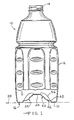
- Figure 1 illustrates an example of a container made from PET which is generally designated at 10.
- the container 10 generally includes a sidewall 12, an upper closure mouth 14, and a base 16.
- the sidewall 12 can be formed into a multitude of different configurations in order to provide the desired aesthetic intent, product identification and structural characteristics.
- the mouth 14 is adapted to receive a threaded closure cap (not shown) and is a rigid ring which can withstand the mechanical loads imposed by such a cap.
- the base 16 includes a peripheral ring 18, which defines a support plane 20, and a generally concave dome 22 extending upwardly into the body cavity 11 of the container 10 and terminating in a centrally located disk 24.
- the dome 22 surface may be spherical, parabolic, conical, tapered or similarly contoured.
- the configuration of the base 16 which incorporates the features of the present invention will be described in greater detail below.
- a preform 26 having a shape similar to a laboratory test tube, is positioned inside of a blow mold 28.
- the blow mold 28 is comprised of a right mold half 30, a left mold half 32 and a mold bottom 34.
- the preform 26 is heated and a plunger 36 is used to axially elongate the preform.
- the preform 26 is also expanded through differential pressure provided via a port 38 in the plunger 36.
- the preform 26 is expanded until conforming to the inner surface of the mold 28.
- the container 10 undergoes a combination of both axial and radial elongation. As previously mentioned, an insufficient elongation will give rise to retractive stresses in the final product.
- the retractive stresses become increasingly significant as one progresses outwardly into a transition region 40, located between the center disk 24 and a uniformly oriented portion 42 adjacent the peripheral ring 18.
- the material of the transition region 40 begins to undergo increased elongation, relative to the center disk 24.
- the PET of this transition region 40 is insufficiently stretched and oriented and therefore particularly susceptible to the random and asymmetrical buckling induced by various thermal and mechanical stresses.
- the mold halves 30 and 32 are provided with coolant passages 44 to control the temperature of the mold 28 itself. Providing different temperatures within the mold 28 enables different material characteristics to be produced in designated areas of the container 10.
- the use of this type of mold is described in U.S. Patent 4,497,855 and 4,318,882, and are hereby incorporated by reference.
- the abovementioned patents describe a container which is molded into a first configuration and then remolded into an increased volume second configuration which allows the container to return to its original configuration, in response to the PET's "memory", as a hot-filled liquid contracts during cooling.
- a container 10 in accordance with this invention may also be formed using the technology disclosed in those patents.
- the base portion 16 is best described with reference to Figures 3, 4 and 5.
- the center of the concave dome 22 is defined by a thick center disk 24, as mentioned previously.
- the tangent vector to any point along the spiral path would thus be changing in three directions and the path would represent a continuously varying three dimensional path.
- the curvature of the ribs 46 could be represented mathematically by various curves, including, but not limited to, an involute, an Archimedean spiral, a parabolic spiral, or a logarthmic spiral.
- An Archimedean spiral may be defined as the plane curve generated by a point moving toward or away from a fixed point at a constant rate while the radius vector from the fixed point rotates at a constant rate.
- the present embodiment displays eight ribs because this number provides for a spacing of the ribs 46 in which the space between adjacent ribs 46 approximates the width of a rib so that the base structure dome 22 is substantially totally filled with an array of ribs 46.
- a greater or lesser number of ribs may be employed so long as they fill the dome 22.
- Each rib 46 arcs about the central disk 24, at an increasing distance therefrom and generally downward along the dome 22 until fading out and terminating at an annular, and generally upright, reinforcing rim 48.
- the annular rim 48 defines an area connecting the peripheral ring 18 to the dome 22. Rounded inwardly, the outer sidewall 12 of the container 10 defines the exterior edge of the peripheral ring 18 and base 16.
- each rib 46 has a cross-sectional shape corresponding to a general horseshoe configuration 50.
- the horseshoe 50 is positioned so that the closed bend 52 is positioned and raised upwardly into the body cavity 11 of the container 10.
- each rib 46 is also raised into the body cavity 11.
- Each rib 46 avoids the introduction of sharp corners in order to prevent the development of further stress concentrations.
- each slide 54 Between each adjacent rib 46 extends a spiral slide portion 54.
- Each slide 54 like each rib 46, originates at the central disk 24 and radiates outward and downward along a three dimensional curve until also terminating at the annular rim 48 adjacent to the peripheral ring 18.
- the curvature of the slides 54 could be mathematically represented by various curves, including an involute, an Archimedean spiral, parabolic spiral or logarthmic spiral.
- the spiral configuration of the base portion 16 provides a number of benefits.
- the horseshoe 50 cross-sectional shape of the spiral ribs 46 provides structural rigidity and reinforcement throughout the base 16 against both the dimensional changes caused by unrelaxed retractive stresses when the PET is at an elevated temperature and dimensional changes caused by increased internal pressure. While needed reinforcement is provided in the transition region 40, the spiral ribs 46 also continue into the uniformly oriented outer portion 42 to provide structural support. This spiraling nature of the present invention significantly enables the overall area of the transition region 40 to be reduced while further increasing the overall area of uniformly oriented PET 42 in the base 16.
- the present invention varies from the blow molding technology of today in that a number of undeformed and insufficiently stretched radial sections are not required as load bearing members in the base 16.
- the spiral ribs 46 and slides 54 both induce a greater amount of stretch.
- the spiral ribs 46 also provide the needed load bearing capacity.
- the horseshoe shape 50 of the ribs 46 provide structural reinforcement throughout the base 16, and particularly around the central disk 24, to withstand internal pressure increases within the container 10 resulting from handling or sudden impact. As a result, the overall amount of insufficiently oriented PET material is reduced without sacrificing structural rigidity in the base 16.
Landscapes
- Engineering & Computer Science (AREA)
- Mechanical Engineering (AREA)
- Manufacturing & Machinery (AREA)
- Ceramic Engineering (AREA)
- Containers Having Bodies Formed In One Piece (AREA)
- Blow-Moulding Or Thermoforming Of Plastics Or The Like (AREA)
Applications Claiming Priority (2)
| Application Number | Priority Date | Filing Date | Title |
|---|---|---|---|
| US452638 | 1989-12-19 | ||
| US07/452,638 US4993566A (en) | 1989-12-19 | 1989-12-19 | Spiral container base structure for hot fill pet container |
Publications (1)
| Publication Number | Publication Date |
|---|---|
| EP0434187A1 true EP0434187A1 (en) | 1991-06-26 |
Family
ID=23797287
Family Applications (1)
| Application Number | Title | Priority Date | Filing Date |
|---|---|---|---|
| EP90310853A Withdrawn EP0434187A1 (en) | 1989-12-19 | 1990-10-04 | Spiral container base structure for hot fill pet container |
Country Status (9)
| Country | Link |
|---|---|
| US (1) | US4993566A (cs) |
| EP (1) | EP0434187A1 (cs) |
| JP (1) | JPH03187830A (cs) |
| AU (1) | AU625480B2 (cs) |
| CA (1) | CA2025492A1 (cs) |
| CS (1) | CS630390A3 (cs) |
| HU (1) | HUT57663A (cs) |
| PL (1) | PL288310A1 (cs) |
| RU (1) | RU1838197C (cs) |
Cited By (1)
| Publication number | Priority date | Publication date | Assignee | Title |
|---|---|---|---|---|
| CN103817911A (zh) * | 2014-02-13 | 2014-05-28 | 江苏星A包装机械集团有限公司 | 无菌吹灌旋生产线中的隐蔽型模具冷却水路布置结构 |
Families Citing this family (55)
| Publication number | Priority date | Publication date | Assignee | Title |
|---|---|---|---|---|
| US5261544A (en) * | 1992-09-30 | 1993-11-16 | Kraft General Foods, Inc. | Container for viscous products |
| US5503283A (en) * | 1994-11-14 | 1996-04-02 | Graham Packaging Corporation | Blow-molded container base structure |
| US6059139A (en) * | 1996-03-21 | 2000-05-09 | Landreneau; Randall L. | Container bottom configuration for improved submersibility in ice |
| US5959066A (en) * | 1998-04-23 | 1999-09-28 | Hna Holdings, Inc. | Polyesters including isosorbide as a comonomer and methods for making same |
| US5958581A (en) * | 1998-04-23 | 1999-09-28 | Hna Holdings, Inc. | Polyester film and methods for making same |
| US6063495A (en) * | 1998-04-23 | 2000-05-16 | Hna Holdings, Inc. | Polyester fiber and methods for making same |
| US6126992A (en) * | 1998-04-23 | 2000-10-03 | E.I. Dupont De Nemours And Company | Optical articles comprising isosorbide polyesters and method for making same |
| US6063464A (en) * | 1998-04-23 | 2000-05-16 | Hna Holdings, Inc. | Isosorbide containing polyesters and methods for making same |
| US6025061A (en) * | 1998-04-23 | 2000-02-15 | Hna Holdings, Inc. | Sheets formed from polyesters including isosorbide |
| US6140422A (en) * | 1998-04-23 | 2000-10-31 | E.I. Dupont De Nemours And Company | Polyesters including isosorbide as a comonomer blended with other thermoplastic polymers |
| US6063465A (en) * | 1998-04-23 | 2000-05-16 | Hna Holdings, Inc. | Polyester container and method for making same |
| USD428814S (en) * | 1998-09-14 | 2000-08-01 | Schmalbach-Lubeca Ag | Container |
| US6065624A (en) * | 1998-10-29 | 2000-05-23 | Plastipak Packaging, Inc. | Plastic blow molded water bottle |
| USD420587S (en) * | 1998-11-20 | 2000-02-15 | Crown Cork & Seal Technologies Corporation | Bottle with integrated grip portion |
| US6164474A (en) * | 1998-11-20 | 2000-12-26 | Crown Cork & Seal Technologies Corporation | Bottle with integrated grip portion |
| USD431465S (en) * | 1998-11-20 | 2000-10-03 | Crown Cork & Seal Technologies Corporation | Bottle with integrated grip portion |
| USD448672S1 (en) | 2000-02-11 | 2001-10-02 | Crown Cork & Seal Technologies Corporation | Container |
| USD448303S1 (en) | 2000-02-11 | 2001-09-25 | Crown Cork & Seal Technologies Corporation | Container |
| USD448304S1 (en) | 2000-07-21 | 2001-09-25 | Crown Cork & Seal Technologies Corporation | Container |
| USD448302S1 (en) | 2000-07-21 | 2001-09-25 | Crown Cork & Seal Technologies Corporation | Container |
| US7543713B2 (en) * | 2001-04-19 | 2009-06-09 | Graham Packaging Company L.P. | Multi-functional base for a plastic, wide-mouth, blow-molded container |
| US6409035B1 (en) | 2000-11-28 | 2002-06-25 | Plastipak Packaging, Inc. | Hollow plastic bottles |
| EP1217318A1 (en) * | 2000-12-19 | 2002-06-26 | Sea Marconi Technologies Di Wander Tumiatti S.A.S. | Plant for the thermal treatment of material and operation process thereof |
| USD459946S1 (en) | 2001-04-30 | 2002-07-09 | Boyd I. Willat | Beverage tasting vessel |
| US6409374B1 (en) | 2001-04-30 | 2002-06-25 | Boyd I. Willat | Beverage tasting vessel with aerating ridges and agitating ribs |
| WO2002098752A1 (en) | 2001-06-04 | 2002-12-12 | Crown Cork & Seal Technologies Corporation | Hot-fillable container with grip |
| US6634517B2 (en) * | 2001-09-17 | 2003-10-21 | Crown Cork & Seal Technologies Corporation | Base for plastic container |
| USD486071S1 (en) | 2001-09-25 | 2004-02-03 | Constar International Inc. | Beverage bottle with hand grip |
| USD482287S1 (en) | 2002-05-10 | 2003-11-18 | Constar International, Inc. | Grippable bottle |
| FR2856380B1 (fr) * | 2003-06-19 | 2005-10-21 | Sidel Sa | Recipient en materiau thermoplastique et a fond champagne |
| US20070119726A1 (en) * | 2004-11-01 | 2007-05-31 | Willat | Wine glass |
| US7886924B2 (en) | 2003-11-05 | 2011-02-15 | By The Glass, Llc | Wine glass |
| US8567635B2 (en) | 2003-11-05 | 2013-10-29 | By The Glass, Llc | Wine glass |
| AU2004289219B2 (en) * | 2003-11-05 | 2010-02-04 | Govino, Llc | Wine glass |
| US9089233B2 (en) | 2003-11-05 | 2015-07-28 | Govino, Llc | Wine glass |
| USD536255S1 (en) | 2004-08-04 | 2007-02-06 | Cadbury Schweppes Plc | Bottle with grip |
| USD533785S1 (en) | 2004-08-04 | 2006-12-19 | Cadbury Schweppes Plc | Grip for bottle |
| USD518722S1 (en) | 2004-08-04 | 2006-04-11 | Cadbury Schweppes Plc | Bottle |
| US7543717B2 (en) * | 2004-08-16 | 2009-06-09 | Hinkle Allen J | Bouquet enhancing wineglass |
| US7416089B2 (en) * | 2004-12-06 | 2008-08-26 | Constar International Inc. | Hot-fill type plastic container with reinforced heel |
| JP4642601B2 (ja) * | 2005-08-23 | 2011-03-02 | 株式会社吉野工業所 | ボトル |
| LT5357B (lt) | 2005-09-02 | 2006-08-25 | Vitalijus Rumbutis | Talpa |
| LT5356B (lt) | 2005-09-02 | 2006-08-25 | Vitalijus Rumbutis | Talpa |
| US7780025B2 (en) * | 2005-11-14 | 2010-08-24 | Graham Packaging Company, L.P. | Plastic container base structure and method for hot filling a plastic container |
| USD547651S1 (en) | 2005-11-14 | 2007-07-31 | Graham Packaging Company, L.P. | Container base |
| EP2025603A1 (fr) * | 2007-07-11 | 2009-02-18 | Aisapack Holding SA | Bouteille plastique pour remplissage à chaud ou traitement thermique |
| US20100122919A1 (en) * | 2008-11-18 | 2010-05-20 | Burroughs James R | Beverage glass with internal decanting, filtering,mixing and aerating cell |
| US8101222B2 (en) * | 2008-11-18 | 2012-01-24 | Chevalier Collection, Ltd. | Beverage glass with internal decanting, filtering, mixing and aerating cell |
| US20110084046A1 (en) * | 2009-10-08 | 2011-04-14 | Graham Packaging Company, L.P. | Plastic container having improved flexible panel |
| PE20141925A1 (es) | 2011-08-31 | 2014-12-05 | Amcor Ltd | Base de recipiente de peso ligero |
| EP2781461B1 (en) * | 2011-11-18 | 2016-11-02 | Toyo Seikan Group Holdings, Ltd. | Container consisting of synthetic resin |
| ITTV20120071A1 (it) * | 2012-05-04 | 2013-11-05 | Pet Engineering S R L | Bottiglia di materiale polimerico |
| JP6257338B2 (ja) * | 2014-01-14 | 2018-01-10 | 三笠産業株式会社 | 合成樹脂製ボトル |
| WO2016029023A1 (en) | 2014-08-21 | 2016-02-25 | Amcor Limited | Container base including hemispherical actuating diaphragm |
| FR3076818B1 (fr) * | 2018-01-18 | 2019-12-13 | Sidel Participations | Recipient comprenant un fond voute presentant des bossages de rigidification repartis en bandes annulaires imbriquees |
Citations (3)
| Publication number | Priority date | Publication date | Assignee | Title |
|---|---|---|---|---|
| US4318882A (en) * | 1980-02-20 | 1982-03-09 | Monsanto Company | Method for producing a collapse resistant polyester container for hot fill applications |
| US4497855A (en) * | 1980-02-20 | 1985-02-05 | Monsanto Company | Collapse resistant polyester container for hot fill applications |
| US4598831A (en) * | 1983-10-31 | 1986-07-08 | Nissei Asb Machine Co., Ltd. | Heat-resistant synthetic resin bottle |
Family Cites Families (10)
| Publication number | Priority date | Publication date | Assignee | Title |
|---|---|---|---|---|
| US4036926A (en) * | 1975-06-16 | 1977-07-19 | Owens-Illinois, Inc. | Method for blow molding a container having a concave bottom |
| FR2379443A1 (fr) * | 1977-02-04 | 1978-09-01 | Solvay | Corps creux en matiere thermoplastique |
| FR2382373A1 (fr) * | 1977-03-02 | 1978-09-29 | Solvay | Corps creux en matiere thermoplastique |
| JPS61144012A (ja) * | 1984-12-18 | 1986-07-01 | 株式会社 精研 | コンデンサ素子の姿勢制御方法 |
| JPS6228335A (ja) * | 1985-07-16 | 1987-02-06 | 山村硝子株式会社 | プラスチツク製容器の底部構造 |
| US4877141A (en) * | 1986-10-03 | 1989-10-31 | Yoshino Kogyosho Co., Ltd. | Pressure resistant bottle-shaped container |
| DE3880708T2 (de) * | 1987-02-17 | 1993-08-19 | Yoshino Kogyosho Co Ltd | Druckfester flaschenartiger behaelter. |
| US4863046A (en) * | 1987-12-24 | 1989-09-05 | Continental Pet Technologies, Inc. | Hot fill container |
| AU626878B2 (en) * | 1988-06-24 | 1992-08-13 | Hoover Universal Inc. | Polyester container for hot fill liquids |
| JPH02235041A (ja) * | 1989-03-09 | 1990-09-18 | Fuji Photo Film Co Ltd | カメラプロセサ及び該カメラプロセサによる版下作成方法 |
-
1989
- 1989-12-19 US US07/452,638 patent/US4993566A/en not_active Expired - Fee Related
-
1990
- 1990-09-17 CA CA002025492A patent/CA2025492A1/en not_active Abandoned
- 1990-10-02 AU AU63722/90A patent/AU625480B2/en not_active Ceased
- 1990-10-04 EP EP90310853A patent/EP0434187A1/en not_active Withdrawn
- 1990-11-21 JP JP2314508A patent/JPH03187830A/ja active Pending
- 1990-12-03 HU HU908038A patent/HUT57663A/hu unknown
- 1990-12-17 CS CS906303A patent/CS630390A3/cs unknown
- 1990-12-18 RU SU904831964A patent/RU1838197C/ru active
- 1990-12-18 PL PL28831090A patent/PL288310A1/xx unknown
Patent Citations (3)
| Publication number | Priority date | Publication date | Assignee | Title |
|---|---|---|---|---|
| US4318882A (en) * | 1980-02-20 | 1982-03-09 | Monsanto Company | Method for producing a collapse resistant polyester container for hot fill applications |
| US4497855A (en) * | 1980-02-20 | 1985-02-05 | Monsanto Company | Collapse resistant polyester container for hot fill applications |
| US4598831A (en) * | 1983-10-31 | 1986-07-08 | Nissei Asb Machine Co., Ltd. | Heat-resistant synthetic resin bottle |
Cited By (2)
| Publication number | Priority date | Publication date | Assignee | Title |
|---|---|---|---|---|
| CN103817911A (zh) * | 2014-02-13 | 2014-05-28 | 江苏星A包装机械集团有限公司 | 无菌吹灌旋生产线中的隐蔽型模具冷却水路布置结构 |
| CN103817911B (zh) * | 2014-02-13 | 2015-12-02 | 江苏星A包装机械集团有限公司 | 无菌吹灌旋生产线中的隐蔽型模具冷却水路布置结构 |
Also Published As
| Publication number | Publication date |
|---|---|
| HUT57663A (en) | 1991-12-30 |
| AU6372290A (en) | 1991-06-27 |
| US4993566A (en) | 1991-02-19 |
| AU625480B2 (en) | 1992-07-09 |
| CS630390A3 (en) | 1992-04-15 |
| PL288310A1 (en) | 1991-12-02 |
| RU1838197C (ru) | 1993-08-30 |
| CA2025492A1 (en) | 1991-06-20 |
| JPH03187830A (ja) | 1991-08-15 |
| HU908038D0 (en) | 1991-06-28 |
Similar Documents
| Publication | Publication Date | Title |
|---|---|---|
| US4993566A (en) | Spiral container base structure for hot fill pet container | |
| US4993567A (en) | Involute embossment base structure for hot fill PET container | |
| US5005716A (en) | Polyester container for hot fill liquids | |
| EP0277557A2 (en) | Blow molded plastic container | |
| US4704243A (en) | Method for producing a thermoplastic container having a ring-shaped reinforcing zone at its bottom | |
| US5763030A (en) | Biaxially stretch blow-molded article and bottom mold therefor | |
| US4465199A (en) | Pressure resisting plastic bottle | |
| EP0385693B1 (en) | A plastics bottle | |
| US4620639A (en) | Synthetic resin thin-walled bottle | |
| US4108324A (en) | Ribbed bottom structure for plastic container | |
| EP0348147A2 (en) | Polyester container for hot fill liquids | |
| US11565866B2 (en) | Plastic container having a deep-set invertible base and related methods | |
| US20170158371A1 (en) | Lightweight Container Base | |
| US5047271A (en) | Apparatus and process relating to a preform and a container with geodesic reinforcement | |
| EP2240370A2 (en) | Hybrid base design | |
| EP0365945B1 (en) | Container | |
| US11091289B2 (en) | Lightweight container base | |
| JP3797156B2 (ja) | ボトル状容器のブロー成形用プリフォーム | |
| EP3615436A1 (en) | Lightweight container base | |
| WO2011109623A2 (en) | Flexible standing ring for hot-fill container | |
| JPH05254531A (ja) | 耐圧自立容器、その製造方法、及びブロー成形型 | |
| WO2008059256A2 (en) | Method and apparatus for making a container with a pressure accomodating base |
Legal Events
| Date | Code | Title | Description |
|---|---|---|---|
| PUAI | Public reference made under article 153(3) epc to a published international application that has entered the european phase |
Free format text: ORIGINAL CODE: 0009012 |
|
| AK | Designated contracting states |
Kind code of ref document: A1 Designated state(s): AT BE CH DE DK ES FR GB GR IT LI LU NL SE |
|
| 17P | Request for examination filed |
Effective date: 19910524 |
|
| 17Q | First examination report despatched |
Effective date: 19920820 |
|
| STAA | Information on the status of an ep patent application or granted ep patent |
Free format text: STATUS: THE APPLICATION IS DEEMED TO BE WITHDRAWN |
|
| 18D | Application deemed to be withdrawn |
Effective date: 19930622 |