EP0434247A2 - Abschirmung für einen Magneten - Google Patents
Abschirmung für einen Magneten Download PDFInfo
- Publication number
- EP0434247A2 EP0434247A2 EP90313038A EP90313038A EP0434247A2 EP 0434247 A2 EP0434247 A2 EP 0434247A2 EP 90313038 A EP90313038 A EP 90313038A EP 90313038 A EP90313038 A EP 90313038A EP 0434247 A2 EP0434247 A2 EP 0434247A2
- Authority
- EP
- European Patent Office
- Prior art keywords
- magnet
- shield
- axis
- supporting
- adjusting
- Prior art date
- Legal status (The legal status is an assumption and is not a legal conclusion. Google has not performed a legal analysis and makes no representation as to the accuracy of the status listed.)
- Withdrawn
Links
Images
Classifications
-
- G—PHYSICS
- G01—MEASURING; TESTING
- G01R—MEASURING ELECTRIC VARIABLES; MEASURING MAGNETIC VARIABLES
- G01R33/00—Arrangements or instruments for measuring magnetic variables
- G01R33/20—Arrangements or instruments for measuring magnetic variables involving magnetic resonance
- G01R33/28—Details of apparatus provided for in groups G01R33/44 - G01R33/64
- G01R33/42—Screening
- G01R33/421—Screening of main or gradient magnetic field
Definitions
- the present invention pertains to a shield for a magnet.
- An illustrative embodiment of the invention relates to a passive magnetic shield for use with the type of magnet employed in magnetic resonance imaging or spectroscopy to generate the main magnetic field.
- main magnets typically comprise a number of magnetic coils supported along a cylindrical frame around a bore which is of sufficient size to receive a human patient.
- the coils are maintained at an extremely low temperature so that the conducting material forming the coils operates in a superconducting mode. External power requirements for a main magnet are thereby minimized.
- the strong magnetic field generated by the main magnet includes a fringe field, or field component extending into the space around the magnet.
- the fringe field maybe strong enough to interfere with the operation of electronic devices such as pacemakers or other equipment of a medical nature which must be operated in the vicinity of the magnet. Accordingly, various practices have been followed or proposed to prevent the fringe field from exceeding a threshold level beyond a specified distance from the main magnet. Five Gauss has typically been selected as the threshold value, and the term "Five Gauss line" refers to a boundary within which the fringe field exceeds 5 Gauss.
- prior-art shielding systems of the above type may impose non-uniform forces on the respective coils of a magnet.
- the coils are urged out of alignment with one another, so that their respective axes are no longer in colinear relationship.
- the fields of misaligned coils tend to interfere with each other such that the coils heat and lose their superconductivity, or "quench.”
- prior-art systems as exemplified by Forster et al., provide devices for individually adjusting coils to ensure proper alignment. However, the adjusting process may be very tedious, and of limited effect.
- An embodiment of the present invention as disclosed herein provides a shield for a magnet having an associated magnet axis, such as a magnet used to generate the main magnetic field required for magnetic resonance imaging or spectroscopy.
- the shield includes a plurality of elongate members made of specified magnetic shielding material, and further includes means for supporting the elongate members to form respective sides of a substantially closed shield structure which surrounds the magnet and has an associated shield axis. Means are provided for supporting the magnet within the shield structure, and other means are coupled to the supporting means for moving the magnet as a unit relative to the shield structure to align the axis of the magnet in colinear relationship with the axis of the shield structure.
- the shield structure acts as a passive shielding device, i.e., it operates to selectively limit a magnetic field without the need to use external power to generate a countervailing field.
- the shield has been designed to have minimal impact on homogeneity of the base magnet.
- the bore on the end caps of the shield has been optimized to achieve this obejctive.
- the illustrative shield disclosed herein seeks to:
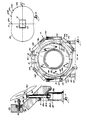
- FIGURE 1 is an end view of a magnetic shield constructed in accordance with the invention surrounding a superconductor magnet of a type used in magnetic resonance imaging, with a portion of the end cap of the shield broken away.
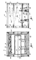
- FIGURE 2 is a side view of the embodiment of Figure 1.
- FIGURE 3 shows a portion of the magnet positioning and adjusting mechanism employed in the embodiment shown in Figure 1.
- FIGURE 4 is a sectional view taken along lines 4-4 of Figure 1.
- FIGURE 5 is an overhead view of the embodiment of Figure 1 showing the position of the 5 Gauss line, as referenced by orthogonal co-ordinates intersecting at the magnet center.
- FIG. 1 shows a shield 10 constructed in accordance with the invention surrounding a magnet 12.
- Shield 10 generally comprises eight similar or identical rectangular plates 14a-14h, an octahedral -shaped end cap or flange 16a, and another octahedral-shaped end cap 16b, identical to end cap 16a, which is not shown in Figure 1.
- the ends of the plates 14a-14h are respectively joined to corresponding sides of the end caps 16a and 16b by means of bolts 18 or the like, in tight-fitting relationship. Side edges of adjacent plates extending between the two end caps are in abutting relationship, and V-shaped gaps are formed therebetween.
- the end caps 16a and 16b rigidly support the plates 14a-14h to form a shield structure which surrounds the magnet 12 and is closed except for opening 20 provided in end cap 16a (and 16b) to enable a patient or other object to be moved into or out of the bore 22 of the magnet 12.
- Figure 1 shows the bottom-most plate 14g positioned directly on a floor or other supporting surface 24. Plates 14a-h are usefully formed of 1006 carbon steel.
- plate 14c comprises two sections 15a and 15b which are butted together along common edges extending longitudinally between end caps 16a and 16b. It has been found to be much more convenient to put plate 14c into position above magnet 12 if it is in two sections rather than in a solid piece.
- Magnet 12 usefully comprises a superconducting magnet for use in magnetic resonance imaging, such as the magnet disclosed in U.S. Patent No. 4,800,354, issued January 24, 1989.
- Such magnet comprises a plurality of discrete magnet coils, supported in coaxial relationship on a coil form (not shown in Fig. 1) positioned around bore 22.
- the magnet coils and coil form are contained in a vessel (not shown) filled with liquid helium, the coils, coil form and helium vessel all being enclosed within a cryostat 26.
- the extreme cold of the liquid helium causes the main coils to become superconductive.
- a component of this field resides in the bore 22, and another component radiates outwardly from the magnet.
- the field component within the bore is used for magnetic resonance imaging and may have a strength on the order of 1.5 Tesla.
- FIG. 1 further shows support pads 28 respectively attached to the outer surface of cryostat 26.
- Each pad has a surface 28a in slidable contact with the upper end of a corresponding vertical support member 30, which traverses one of the plates 14f or 14h.
- Each support member 30 is carried upon a corresponding stand 32 which is positioned on floor 24 and rigidly attached to the shield.
- vertical support members 30 and stands 32 carry the entire weight of cryostat 26 and respective components contained therein, including magnet 12. All of such weight is transferred to the support members 30 through the surfaces 28a.
- the slidable relationship between each pad surface 28a and its corresponding vertical support member 30 allows cryostat 26 and magnet 12 to move horizontally relative to members 30, stands 32 and shield 10.
- each of the vertical members 30 can be raised or lowered relative to its corresponding stand 32 to vertically adjust the position of magnet 12 relative to floor 24 and shield 10.
- Figure 1 shows a plurality of adjustment screws 34, each in threaded engagement with a nut 33 secured to one of the plates 14a or 14e and bearing against a pad 28. Adjustment screws 34 are used to laterally shift cryostat 26 and magnet 12, i.e., to the left or right as viewed in Figure 1, relative to shield 10.
- two adjustment screws 35 are threaded through end cap 16a on opposite sides of bore 22 (only one screw 35 being shown in Figure 1). Screws 35 are fitted into counterbores 37 in cap 16a and bear against the proximate end of cryostat 26. Two other screws 35 are correspondingly threaded through end cap 16b and bear against the opposing end of cryostat 26. The four adjustment screws 35 are used to shift cryostat 26 and magnet 12 axially relative to shield 10.
- Figures 1 and 2 together show that a total of four sets of pads 28, support members 30, stands 32 and screws 34 are provided to selectively position cryostat 26 and thereby magnet 12.
- FIG. 2 shows stands 32 each comprising two vertically oriented plates 32a and 32b which are spaced apart from each other in parallel relationship and rigidly joined to a base plate 32c in contact with floor 24. Plates 32a and 32b are rigidly tied together at their upper portions by means of a horizontally oriented web plate 32d and an angled plate 32e, each provided with an aperture.
- FIG. 2 further shows each vertical support member 30 comprising a rod 30a bearing upon a flange member 30b.
- the aperture in a web plate 32d is sized to receive an end portion 30d extending below flange 30b and of integral construction therewith, so that the flange member 30b can be brought into contact with web 32d to provide a rigid interface therebetween.
- the downward loading imposed on a vertical support member 30 by cryostat 16 and magnet 12 contained therein is solidly taken up across such interface by the corresponding stand 32.
- one or more shims 36 may be positioned between web plate 32d and flange 30b.
- the shims comprise rigid steel members of selected thickness, and are each provided with an aperture sized to allow traversal by the end portion 30d.
- the height of magnet 12 relative to floor 24 is usefully variable over a range on the order of 1.0 inches, according to the number and thickness of shims positioned between the flanges 30b and corresponding plates 32d.
- FIG. 3 shows in greater detail an adjustment screw 34 in threaded engagement with a nut 33, which is immovably held in a counterbore 38 formed in one of the plates such as 14e such as by means of bolts 39.
- Adjustment screw 34 is provided with wrench flats 40 which may be engaged by a wrench to selectively rotate screw 34 and thereby urge the screw to bear against or to back away from an attachment structure 30.
- Figure 3 further shows the angled plate 32e of a stand 32 positioned at a 45 degree angle to vertical plates 32a and 32b, and attached to the shield 10 by means of bolts 41.
- a teflon or delrin pad 30c is usefully placed on the upper end of each rod 30a to allow the pad surface 28a in contact therewith to move freely relative thereto.
- Figure 4 shows magnet 12 comprising a plurality of circular coils 12a-12d, respectively wound upon a cylindrical coil form 13 which is rigidly supported by walls of cryostat 26.
- Coil form 13 maintains coils 12a-d in immovable relationship with one another, so that their respective axes are all aligned along a common axis A m , the axis of magnet 12.
- magnet 12 is shown to comprise four coils for purposes of illustration, but in fact could comprise a different number of coils.
- Magnet axis A m must be aligned with the axis A s of shield 10 in order to ensure proper operation of magnet 12 when shield 10 is in place around cryostat 26. Misalignment between these axes can result in quenching of magnet 12, and can impact on the homogeneity of the magnetic field within bore 22 such that magnetic resonance imaging of an object in the bore is adversely affected. Since respective coils 12a-d of magnet 12 are rigidly joined to cryostat 26 through coil form 13, magnet axis A m is most effectively brought into alignment with shield axis A s by selective vertical and lateral displacement of cryostat 26, in view of the much greater weight of the shield. The required vertical displacement is within the range of variation which can be provided by means of shims 36.
- the required lateral displacement is within the range of variation which can be provided by adjustment screws 34.
- magnet axis A m can be aligned with shield axis A s to within 1/16 of an inch or less.
- Figure 4 further shows adjustment screws 35 traversing corresponding holes respectively formed through end caps 16a and 16b, and engaging threads of nuts respectively attached thereto such as nuts 33 shown in Figure 3 in connection with screws 34.
- magnet 12 can be axially shifted relative to shield 10, i.e., shifted along axis A s , over a range on the order of 1.0 inch.
- Figure 5 shows a magnet 12 enclosed within shield 10 generating a 1.5 Tesla magnetic field and having a 5 Gauss line 42.
- Five Gauss line 42 is a curve generated to fit data points 42a-f, each of which was obtained by actual measurement of the fringe field generated by magnet 12 when enclosed by the shield 10.
- Five Gauss line 42 intersects an axis designated as the Z-axis, coinciding with the magnet axis A m , at a distance of 19.5 feet from the magnet center.
- the Five Gauss line intersects an axis designated as the R-axis, orthogonal to the Z-axis, at a distance of 12 feet from the magnet center 44.
Landscapes
- Physics & Mathematics (AREA)
- Health & Medical Sciences (AREA)
- Epidemiology (AREA)
- Condensed Matter Physics & Semiconductors (AREA)
- General Physics & Mathematics (AREA)
- Magnetic Resonance Imaging Apparatus (AREA)
- Regulation Of General Use Transformers (AREA)
- Shielding Devices Or Components To Electric Or Magnetic Fields (AREA)
Applications Claiming Priority (2)
| Application Number | Priority Date | Filing Date | Title |
|---|---|---|---|
| US07/452,087 US5001448A (en) | 1989-12-18 | 1989-12-18 | Shield for a magnet |
| US452087 | 1989-12-18 |
Publications (2)
| Publication Number | Publication Date |
|---|---|
| EP0434247A2 true EP0434247A2 (de) | 1991-06-26 |
| EP0434247A3 EP0434247A3 (en) | 1991-10-30 |
Family
ID=23794972
Family Applications (1)
| Application Number | Title | Priority Date | Filing Date |
|---|---|---|---|
| EP19900313038 Withdrawn EP0434247A3 (en) | 1989-12-18 | 1990-11-30 | Shield for a magnet |
Country Status (5)
| Country | Link |
|---|---|
| US (1) | US5001448A (de) |
| EP (1) | EP0434247A3 (de) |
| JP (1) | JP2598838B2 (de) |
| CA (1) | CA2021599A1 (de) |
| IL (1) | IL96543A0 (de) |
Cited By (2)
| Publication number | Priority date | Publication date | Assignee | Title |
|---|---|---|---|---|
| DE19638230C1 (de) * | 1996-09-19 | 1998-05-28 | Bruker Analytische Messtechnik | Ferromagnetische Raumabschirmung für den supraleitenden Hochfeldmagneten eines NMR-Spektrometers |
| EP1553423A1 (de) * | 2004-01-06 | 2005-07-13 | GE Medical Systems Global Technology Company LLC | Verfahren und Gerät für Kernspintomographie |
Families Citing this family (20)
| Publication number | Priority date | Publication date | Assignee | Title |
|---|---|---|---|---|
| SE463416B (sv) * | 1988-09-02 | 1990-11-19 | Sandvik Ab | Oxidbaserat keramiskt material foer spaanavskiljande bearbetning av staal |
| US5220302A (en) * | 1990-01-22 | 1993-06-15 | The University Of Texas System Board Of Regents | Nmr clinical chemistry analyzer and method of forming a shield |
| JPH0420326A (ja) * | 1990-05-15 | 1992-01-23 | Toshiba Corp | Mri装置用静磁界磁石装置 |
| JPH04328477A (ja) * | 1991-04-30 | 1992-11-17 | Mitsubishi Electric Corp | 電磁石装置 |
| US5359310A (en) * | 1992-04-15 | 1994-10-25 | Houston Advanced Research Center | Ultrashort cylindrical shielded electromagnet for magnetic resonance imaging |
| US5382904A (en) * | 1992-04-15 | 1995-01-17 | Houston Advanced Research Center | Structured coil electromagnets for magnetic resonance imaging and method for fabricating the same |
| US5304934A (en) * | 1993-01-04 | 1994-04-19 | General Electric Company | Superconducting magnet for imaging human limbs |
| US6416215B1 (en) | 1999-12-14 | 2002-07-09 | University Of Kentucky Research Foundation | Pumping or mixing system using a levitating magnetic element |
| US6758593B1 (en) * | 2000-10-09 | 2004-07-06 | Levtech, Inc. | Pumping or mixing system using a levitating magnetic element, related system components, and related methods |
| US6973711B1 (en) * | 2000-05-24 | 2005-12-13 | Fonar Corporation | Method for making pieces for a magnetic resonance imaging magnet |
| US6677752B1 (en) * | 2000-11-20 | 2004-01-13 | Stereotaxis, Inc. | Close-in shielding system for magnetic medical treatment instruments |
| ITSV20010034A1 (it) * | 2001-10-02 | 2003-04-02 | Esaote Spa | Magnete a superconduttore in particolare per macchine di rilevamento di immagini in risonanza magnetica nucleare |
| JP4742502B2 (ja) * | 2004-02-23 | 2011-08-10 | ソニー株式会社 | 磁気シールド体、磁気シールド構造及び磁気メモリ装置 |
| CN100434038C (zh) * | 2004-03-05 | 2008-11-19 | 西门子(中国)有限公司 | 磁共振成像设备磁场的调节装置 |
| GB0503622D0 (en) * | 2005-02-22 | 2005-03-30 | Siemens Magnet Technology Ltd | Shielding for mobile MRI systems |
| US8514043B2 (en) * | 2005-09-14 | 2013-08-20 | General Electric Company | Systems and methods for passively shielding a magnetic field |
| JP4796393B2 (ja) * | 2006-01-17 | 2011-10-19 | 株式会社日立製作所 | 超電導電磁石 |
| US9177707B2 (en) | 2012-04-20 | 2015-11-03 | Mitsubishi Electric Corporation | Superconducting magnet and method for adjusting the same |
| JP2017011236A (ja) * | 2015-06-26 | 2017-01-12 | 株式会社神戸製鋼所 | 多層磁気シールド |
| US10182652B1 (en) * | 2017-12-21 | 2019-01-22 | Google Llc | Interactive kiosk shelves |
Family Cites Families (9)
| Publication number | Priority date | Publication date | Assignee | Title |
|---|---|---|---|---|
| JPS503498B2 (de) * | 1971-09-18 | 1975-02-05 | ||
| DE3333755A1 (de) * | 1983-09-19 | 1985-04-18 | Siemens AG, 1000 Berlin und 8000 München | Magneteinrichtung einer anlage der kernspin-tomographie mit einer abschirmvorrichtung |
| DE3769194D1 (de) * | 1986-04-21 | 1991-05-16 | Siemens Ag | Rahmenstruktur fuer ein magnetsystem einer anlage zur kernspin-tomographie. |
| US4931760A (en) * | 1986-10-08 | 1990-06-05 | Asahi Kasei Kogyo Kabushiki Kaisha | Uniform magnetic field generator |
| JP2603944B2 (ja) * | 1986-11-13 | 1997-04-23 | 株式会社東芝 | Mri装置用磁石の磁気遮蔽体 |
| FR2611975B1 (fr) * | 1987-03-03 | 1995-02-17 | Commissariat Energie Atomique | Systeme d'aimants permanents pour un champ magnetique intense |
| JPS63307711A (ja) * | 1987-06-10 | 1988-12-15 | Toshiba Corp | 磁石装置 |
| US4822772A (en) * | 1987-08-14 | 1989-04-18 | Houston Area Research Center | Electromagnet and method of forming same |
| US4743880A (en) * | 1987-09-28 | 1988-05-10 | Ga Technologies Inc. | MRI magnet system having shield and method of manufacture |
-
1989
- 1989-12-18 US US07/452,087 patent/US5001448A/en not_active Expired - Lifetime
-
1990
- 1990-07-19 CA CA002021599A patent/CA2021599A1/en not_active Abandoned
- 1990-11-30 EP EP19900313038 patent/EP0434247A3/en not_active Withdrawn
- 1990-11-30 JP JP2337013A patent/JP2598838B2/ja not_active Expired - Fee Related
- 1990-12-05 IL IL96543A patent/IL96543A0/xx not_active IP Right Cessation
Cited By (4)
| Publication number | Priority date | Publication date | Assignee | Title |
|---|---|---|---|---|
| DE19638230C1 (de) * | 1996-09-19 | 1998-05-28 | Bruker Analytische Messtechnik | Ferromagnetische Raumabschirmung für den supraleitenden Hochfeldmagneten eines NMR-Spektrometers |
| US6172587B1 (en) | 1996-09-19 | 2001-01-09 | Bruker Analytik Gmbh | Ferromagnetic spatial shielding for the superconducting high field magnet of an NMR spectrometer |
| EP1553423A1 (de) * | 2004-01-06 | 2005-07-13 | GE Medical Systems Global Technology Company LLC | Verfahren und Gerät für Kernspintomographie |
| US7019525B2 (en) | 2004-01-06 | 2006-03-28 | Ge Medical Systems Glogal Technology Company, Llc | Method and apparatus for magnetic resonance imaging |
Also Published As
| Publication number | Publication date |
|---|---|
| JPH03191504A (ja) | 1991-08-21 |
| US5001448A (en) | 1991-03-19 |
| EP0434247A3 (en) | 1991-10-30 |
| CA2021599A1 (en) | 1991-06-19 |
| JP2598838B2 (ja) | 1997-04-09 |
| IL96543A0 (en) | 1991-09-16 |
Similar Documents
| Publication | Publication Date | Title |
|---|---|---|
| US5001448A (en) | Shield for a magnet | |
| US6411187B1 (en) | Adjustable hybrid magnetic apparatus | |
| US5389909A (en) | Open architecture magnetic resonance imaging passively shimmed superconducting magnet assembly | |
| US10852375B1 (en) | Magnetic resonance imaging method and apparatus | |
| US5900793A (en) | Permanent magnet assemblies for use in medical applications | |
| US5305749A (en) | Side-loading of patient into MRI C-magnet while maintaining adjacent open accessibility to patient | |
| US6172588B1 (en) | Apparatus and method for a superconductive magnet with pole piece | |
| EP0817211B1 (de) | Supraleitende magnetvorrichtung und bilderzeugungsvorrichtung durch magnetische resonanz unter verwendung derselben | |
| EP0687920B1 (de) | Magnet zur Bilderzeugung mittels magnetischer Resonanz | |
| US6507192B1 (en) | Nuclear magnetic resonance apparatus and methods of use and facilities for incorporating the same | |
| US20020123681A1 (en) | Device and a system for moving and positioning an open magnetic resonance imaging probe | |
| US6150911A (en) | Yoked permanent magnet assemblies for use in medical applications | |
| US5689190A (en) | Magnetic resonance imaging apparatus including a main magnet having opposed pole faces which are inclined with respect to vertical | |
| JPS6090546A (ja) | 核スピン断層撮影設備の磁石装置 | |
| US5361054A (en) | Magnet system | |
| EP1169719A1 (de) | Hybrid magnetisches apparat für medikalische benützung | |
| US8947090B2 (en) | Electromagnet assembly | |
| US20030011451A1 (en) | Permanent magnet assemblies for use in medical applications | |
| GB2476546A (en) | Structural support member allowing alignment adjustment between coil formers in a magnet system | |
| US6889070B2 (en) | Magnetic resonance imaging apparatus and assembly process thereof | |
| US4931759A (en) | Magnetic resonance imaging magnet having minimally symmetric ferromagnetic shield | |
| US6198371B1 (en) | Open magnet with floor mount | |
| US6812702B2 (en) | Magnetic resonance imaging apparatus | |
| US5457388A (en) | Magnetic resonance apparatus including elements for homogenizing the magnetic field | |
| JPS63249552A (ja) | 磁気共鳴イメ−ジング装置 |
Legal Events
| Date | Code | Title | Description |
|---|---|---|---|
| PUAI | Public reference made under article 153(3) epc to a published international application that has entered the european phase |
Free format text: ORIGINAL CODE: 0009012 |
|
| AK | Designated contracting states |
Kind code of ref document: A2 Designated state(s): DE FR GB NL |
|
| PUAL | Search report despatched |
Free format text: ORIGINAL CODE: 0009013 |
|
| AK | Designated contracting states |
Kind code of ref document: A3 Designated state(s): DE FR GB NL |
|
| 17P | Request for examination filed |
Effective date: 19911220 |
|
| 17Q | First examination report despatched |
Effective date: 19950119 |
|
| STAA | Information on the status of an ep patent application or granted ep patent |
Free format text: STATUS: THE APPLICATION IS DEEMED TO BE WITHDRAWN |
|
| 18D | Application deemed to be withdrawn |
Effective date: 19961116 |