EP0434251A2 - Motordrehzahlregler - Google Patents
Motordrehzahlregler Download PDFInfo
- Publication number
- EP0434251A2 EP0434251A2 EP90313065A EP90313065A EP0434251A2 EP 0434251 A2 EP0434251 A2 EP 0434251A2 EP 90313065 A EP90313065 A EP 90313065A EP 90313065 A EP90313065 A EP 90313065A EP 0434251 A2 EP0434251 A2 EP 0434251A2
- Authority
- EP
- European Patent Office
- Prior art keywords
- vehicle
- engine
- governor
- speed
- fuel
- Prior art date
- Legal status (The legal status is an assumption and is not a legal conclusion. Google has not performed a legal analysis and makes no representation as to the accuracy of the status listed.)
- Granted
Links
Images
Classifications
-
- F—MECHANICAL ENGINEERING; LIGHTING; HEATING; WEAPONS; BLASTING
- F02—COMBUSTION ENGINES; HOT-GAS OR COMBUSTION-PRODUCT ENGINE PLANTS
- F02D—CONTROLLING COMBUSTION ENGINES
- F02D41/00—Electrical control of supply of combustible mixture or its constituents
- F02D41/30—Controlling fuel injection
- F02D41/38—Controlling fuel injection of the high pressure type
-
- F—MECHANICAL ENGINEERING; LIGHTING; HEATING; WEAPONS; BLASTING
- F02—COMBUSTION ENGINES; HOT-GAS OR COMBUSTION-PRODUCT ENGINE PLANTS
- F02D—CONTROLLING COMBUSTION ENGINES
- F02D31/00—Use of speed-sensing governors to control combustion engines, not otherwise provided for
- F02D31/001—Electric control of rotation speed
-
- F—MECHANICAL ENGINEERING; LIGHTING; HEATING; WEAPONS; BLASTING
- F02—COMBUSTION ENGINES; HOT-GAS OR COMBUSTION-PRODUCT ENGINE PLANTS
- F02D—CONTROLLING COMBUSTION ENGINES
- F02D2250/00—Engine control related to specific problems or objectives
- F02D2250/18—Control of the engine output torque
Definitions
- This invention relates to a governor system for the fuel pump of an internal combustion engine which in use powers a road vehicle.
- a road vehicle used for transporting goods for example an articulated vehicle it is the usual practice to provide a so-called all-speed governor system since the characteristic provided by such a system is ideal for use when the vehicle is in a loaded state.
- the driver of the vehicle sets the required engine speed and the governor system within the power capability of the engine and any other restraints such as engine exhaust smoke level, adjusts the fuel supply to the engine so as to attain and maintain the required speed.
- the governor system will respond very quickly to changes in the required speed but the response of the vehicle will be much slower because of its loaded state.
- governor system An alternative form of governor system is known as the two-speed system in which the governor system controls the maximum speed and the idling speed of the engine.
- the intermediate speeds are controlled by the vehicle driver since in this system, in the intermediate speed range adjustment of the throttle pedal adjusts directly the amount of fuel supplied to the engine.
- Such a system facilitates the control of the vehicle when it is in an unloaded state but since vehicles are in most cases loaded to their maximum extent the usual practice is to provide an all-speed governor system.
- the vehicle becomes more difficult to control since if the required speed is increased, the governor system will react to increase the fuel supply to the engine to its maximum allowed level and will only start to reduce the level of fuel supply as the new required speed is attained. Similarly if the required speed is reduced the governor system will react to reduce the level of fuel supply to a low value and will only increase the level of fuel supply as the new required speed is attained. In its unladen state therefore the vehicle is difficult to control.
- GB 2069187B proposes a partial solution to the above problem by providing a sensor which is responsive to the loaded state of the vehicle. The signal from the sensor is utilised to modify the governor characteristic. This solution is not entirely satisfactory and the object of the present invention is to provide a governor system in an improved form.
- a governor system for the fuel pump of an internal combustion engine which drives a road vehicle through a variable ratio transmission includes a governor having an all-speed characteristic and includes first means responsive to the loaded state of the vehicle and second means responsive to the transmission ratio of the transmission, said first and second means acting to modify the response of the governor in the intermediate speed range.
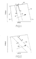
- FIG. 1 of the drawings there is shown the characteristic of an all-speed governor with engine torque being plotted against engine speed.
- the line 10 represents the maximum fuel line which during normal operation of the engine cannot be exceeded.
- the line 11 represents the idle pull-off curve, the normal idling speed of the engine being that corresponding to the point 12.
- the line 13 represents the maximum speed pull-off curve, the point 14 corresponding to the maximum permitted engine speed.
- the lines 15 and 16 lying between the lines 12 and 13 represent different levels of demanded engine speed, the line 16 as indicated by the arrow, representing a higher demand than the line 15.
- the engine is operating at point A in equilibrium that is to say just sufficient fuel is being supplied to the engine to provide sufficient torque to maintain the steady speed of the engine.
- the torque provided by the engine will increase in more or less a step wise manner to the point C. This is because in response to the increased demand, the governor system will move the fuel control member of the fuel pump to a position to provide the maximum fuel.
- the engine speed will increase to the point D and in the particular example, there will be a slight increase in the amount of fuel supplied to the engine.
- Point B represents a new equilibrium position which is established at the new desired speed with the engine torque increased to maintain that speed. It will be noted from Figure 1 that there is a substantial increase in the torque delivered by the engine and this increase in torque results in an increase in torque at the driving wheels of the vehicle.
- the actual torque available at the driving wheels of the vehicle depends upon the gear ratio of the transmission of the vehicle and as a gear is selected which results in a higher engine speed for a given road-speed of the vehicle there will be an increase in the torque multiplication.
- Figure 2 shows modified governor characteristics which show the lines 15A and 16A having a greater reverse slope.
- depression of the throttle pedal will result in an increase in the amount of fuel supplied to the engine but the actual increase will be limited to that which corresponds to point E lying on the line 16A.
- the increase in engine torque is therefore substantially less than that which is shown in Figure 1 and the greater the reverse slope, the smaller the increase in torque which occurs.
- the increase in torque at the driving wheels of the vehicle is reduced and this facilitates control of the vehicle.
- the value of the reverse slope is ideally chosen such that a constant vehicle acceleration results from a uniform increase in demand, this being a direct function of available tractive effort and an inverse function of the vehicle mass according to Newtons first law.
- the system is likely to limit acceleration to acceptable levels in operating regions where low gear ratios and/or low vehicle weight exist with full available engine power being transmitted where this does not inhibit vehicle control or ride comfort.
- a progressive load sensor is used for the derivation or vehicle weight but again this can be comprised practically by sensors which give an indication of the loaded state of the vehicle or even by switch inputs under the control of the vehicle driver.
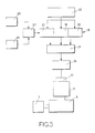
- FIG 3 shows the layout of the governor system and its connection to a fuel control actuator 17 associated with a fuel pump 9 supplying fuel to an engine 8.
- the engine is connected through a multi-ratio gearbox 7 to the powered road wheels of the vehicle.
- the governor generally indicated at 18 includes a first section 19 which controls the supply of fuel to the engine 9 below the normal idling speed.
- Section 20 controls the supply of fuel as the engine speed approaches its maximum speed and section 21 determines the supply of fuel to the engine in the intermediate speed range.
- Each section is supplied with signals corresponding to the actual engine speed and the demanded engine speed, these signals being provided by circuit means 22.
- the outputs of the portions 19, 20 and 21 of the governor system pass to a control circuit 23 which combines the outputs and controls the operation of a power circuit 24 the output of which is connected to the actuator 17.
- the portion 21 also receives signals from sensors 25, 26, sensor 25 being arranged to provide a signal indicative of the loaded state of the vehicle and sensor 26 being arranged to provide an indication of the selected gear ratio of the box 7.
- the outputs of the sensors 25 and 26 are passed to a decoder 27 which supplies a signal to the portion 21 of the governor to determine the slope of the lines 15A and 16A, it being appreciated that these two lines are merely two examples of a large number of lines which can be constructed and lie between the lines 12 and 13.
Landscapes
- Engineering & Computer Science (AREA)
- Chemical & Material Sciences (AREA)
- Combustion & Propulsion (AREA)
- Mechanical Engineering (AREA)
- General Engineering & Computer Science (AREA)
- Electrical Control Of Air Or Fuel Supplied To Internal-Combustion Engine (AREA)
- High-Pressure Fuel Injection Pump Control (AREA)
- Control Of Vehicle Engines Or Engines For Specific Uses (AREA)
- Control Of Driving Devices And Active Controlling Of Vehicle (AREA)
Applications Claiming Priority (2)
| Application Number | Priority Date | Filing Date | Title |
|---|---|---|---|
| GB8928597 | 1989-12-19 | ||
| GB898928597A GB8928597D0 (en) | 1989-12-19 | 1989-12-19 | Governor |
Publications (3)
| Publication Number | Publication Date |
|---|---|
| EP0434251A2 true EP0434251A2 (de) | 1991-06-26 |
| EP0434251A3 EP0434251A3 (en) | 1992-03-04 |
| EP0434251B1 EP0434251B1 (de) | 1994-01-19 |
Family
ID=10668140
Family Applications (1)
| Application Number | Title | Priority Date | Filing Date |
|---|---|---|---|
| EP90313065A Revoked EP0434251B1 (de) | 1989-12-19 | 1990-11-30 | Motordrehzahlregler |
Country Status (6)
| Country | Link |
|---|---|
| US (1) | US5323746A (de) |
| EP (1) | EP0434251B1 (de) |
| JP (1) | JPH06213006A (de) |
| DE (1) | DE69006204T2 (de) |
| ES (1) | ES2050386T3 (de) |
| GB (1) | GB8928597D0 (de) |
Families Citing this family (10)
| Publication number | Priority date | Publication date | Assignee | Title |
|---|---|---|---|---|
| DE4333896B4 (de) * | 1993-10-05 | 2006-12-21 | Robert Bosch Gmbh | Verfahren und Vorrichtung zur Steuerung einer Brennkraftmaschine |
| US5605130A (en) * | 1994-04-15 | 1997-02-25 | Briggs & Stratton Corporation | Electronic governor having increased droop at lower selected speeds |
| DE19540061C1 (de) * | 1995-10-27 | 1996-10-02 | Daimler Benz Ag | Verfahren und Vorrichtung zur Steuerung eines Kraftfahrzeug-Dieselmotors |
| JP3692763B2 (ja) * | 1998-02-24 | 2005-09-07 | いすゞ自動車株式会社 | ディーゼルエンジンの電子制御燃料噴射装置 |
| US6089207A (en) * | 1998-03-02 | 2000-07-18 | Cummins Engine Company, Inc. | Throttle control response selection system |
| US6062197A (en) * | 1998-06-15 | 2000-05-16 | Cummins Engine Company, Inc. | Hybrid power governor |
| US6092504A (en) * | 1998-08-04 | 2000-07-25 | Caterpillar Inc. | Device for controlling engine speed using dual governors |
| SE523469C2 (sv) * | 2001-12-06 | 2004-04-20 | Volvo Lastvagnar Ab | Drivaggregat för motorfordon |
| US7141001B1 (en) * | 2004-11-09 | 2006-11-28 | Daniel Albanesi | Load-variable engine control system |
| US10196066B2 (en) * | 2016-01-11 | 2019-02-05 | Cnh Industrial America Llc | Automotive productivity manager for power shift transmissions |
Family Cites Families (14)
| Publication number | Priority date | Publication date | Assignee | Title |
|---|---|---|---|---|
| GB1466867A (en) * | 1973-04-14 | 1977-03-09 | Cav Ltd | Control system for vehicles |
| DE2820807A1 (de) * | 1978-05-12 | 1979-11-22 | Bosch Gmbh Robert | Einrichtung zum einstellen eines mengenbestimmenden gliedes einer kraftstoffeinspritzpumpe bei einer brennkraftmaschine mit selbstzuendung |
| JPS5612026A (en) * | 1979-07-10 | 1981-02-05 | Fuji Electric Co Ltd | Electric governor for internal combustion engine |
| FR2475632A1 (fr) * | 1980-02-08 | 1981-08-14 | Lucas Industries Ltd | Systeme regulateur pour pompe a carburant de moteur a combustion interne |
| DE3019562A1 (de) * | 1980-05-22 | 1981-11-26 | Daimler-Benz Ag, 7000 Stuttgart | Vorrichtung zum steuern einer brennkraftmaschine |
| JPS5720525A (en) * | 1980-07-14 | 1982-02-03 | Nippon Denso Co Ltd | Electric governor for fuel injection pump |
| JPS57159939A (en) * | 1981-03-30 | 1982-10-02 | Nissan Motor Co Ltd | Electronic controller of fuel injection amount in fuel injection internal combustion engine |
| JPS582430A (ja) * | 1981-06-30 | 1983-01-08 | Hino Motors Ltd | 車両塔載用デイ−ゼル機関の制御装置 |
| JPS582433A (ja) * | 1981-06-30 | 1983-01-08 | Hino Motors Ltd | 車両塔載用デイ−ゼル機関の出力制御方法及び装置 |
| JPS5925039A (ja) * | 1982-07-30 | 1984-02-08 | Hino Motors Ltd | 車両用デイ−ゼル機関の制御装置 |
| JPS5939942A (ja) * | 1982-08-30 | 1984-03-05 | Toyota Motor Corp | デイ−ゼルエンジンの燃料噴射制御装置 |
| JPS59180046A (ja) * | 1983-03-30 | 1984-10-12 | Hino Motors Ltd | 車輛の経済走行装置 |
| JPS62118038A (ja) * | 1985-11-15 | 1987-05-29 | Komatsu Ltd | 車両用エンジンのトルクセツト方法 |
| DE3721605A1 (de) * | 1986-07-01 | 1988-01-14 | Mazda Motor | Steuerungssystem fuer verbrennungsmotoren |
-
1989
- 1989-12-19 GB GB898928597A patent/GB8928597D0/en active Pending
-
1990
- 1990-11-30 ES ES90313065T patent/ES2050386T3/es not_active Expired - Lifetime
- 1990-11-30 EP EP90313065A patent/EP0434251B1/de not_active Revoked
- 1990-11-30 DE DE69006204T patent/DE69006204T2/de not_active Revoked
- 1990-12-18 JP JP2411291A patent/JPH06213006A/ja active Pending
-
1992
- 1992-04-08 US US07/865,705 patent/US5323746A/en not_active Expired - Fee Related
Also Published As
| Publication number | Publication date |
|---|---|
| EP0434251A3 (en) | 1992-03-04 |
| GB8928597D0 (en) | 1990-02-21 |
| JPH06213006A (ja) | 1994-08-02 |
| ES2050386T3 (es) | 1994-05-16 |
| US5323746A (en) | 1994-06-28 |
| DE69006204D1 (de) | 1994-03-03 |
| EP0434251B1 (de) | 1994-01-19 |
| DE69006204T2 (de) | 1994-07-07 |
Similar Documents
| Publication | Publication Date | Title |
|---|---|---|
| US4281567A (en) | System for optimizing the fuel consumption of an internal combustion engine | |
| EP0953470B1 (de) | Steuerungsverfahren für Fahrzeug mit stufenlosem, verstellbarem Getriebe. | |
| US5681238A (en) | Method and an apparatus for controlling a car equipped with an automatic transmission having a lockup clutch | |
| US4484497A (en) | Fuel cut-off system for an engine coupled to an automatic power transmission with a lockup device | |
| KR100214398B1 (ko) | 무단 변속기의 제어 장치 | |
| JP3375123B2 (ja) | 自動車のドライブトレイン制御装置 | |
| US5819705A (en) | Process and system for controlling a motor vehicle diesel engine | |
| US4945481A (en) | System for integrally controlling automatic transmission and engine | |
| US4807132A (en) | Apparatus for controlling an internal combustion engine for vehicles | |
| US5522778A (en) | Automatic transmission with power take-off unit | |
| EP0434251B1 (de) | Motordrehzahlregler | |
| US4359028A (en) | Apparatus for providing uniform acceleration for an internal combustion engine | |
| JP2003529713A (ja) | 車両における駆動ユニットの制御方法および装置 | |
| JP2000508596A (ja) | 車両駆動機関の制御方法および装置 | |
| US4612827A (en) | Accelerator control for a vehicular propulsion system having a continuously variable ratio transmission | |
| KR100749193B1 (ko) | 차량의 구동 유닛 제어를 위한 장치 및 방법 | |
| JP2000512713A (ja) | 内燃機関の制御方法及び装置 | |
| US4560021A (en) | Control system for a plurality of engine units | |
| JPH09119328A (ja) | エンジン出力制御装置 | |
| US6883493B2 (en) | Method and device for operating the drive motor of a vehicle | |
| US5551932A (en) | Engine idle control during braking with lockup clutch being released | |
| JP3403420B2 (ja) | 自動車の制御装置 | |
| US4899623A (en) | Control system for internal combustion engines | |
| US6364808B1 (en) | Apparatus for changing the transmission ratio of a continuously adjustable transmission as part of a cruise control system for motor vehicles | |
| EP0477082A2 (de) | Zugkraftsteuerungssystem für Kraftfahrzeug |
Legal Events
| Date | Code | Title | Description |
|---|---|---|---|
| PUAI | Public reference made under article 153(3) epc to a published international application that has entered the european phase |
Free format text: ORIGINAL CODE: 0009012 |
|
| AK | Designated contracting states |
Kind code of ref document: A2 Designated state(s): DE ES FR GB IT |
|
| PUAL | Search report despatched |
Free format text: ORIGINAL CODE: 0009013 |
|
| AK | Designated contracting states |
Kind code of ref document: A3 Designated state(s): DE ES FR GB IT |
|
| 17P | Request for examination filed |
Effective date: 19920609 |
|
| 17Q | First examination report despatched |
Effective date: 19921124 |
|
| GRAA | (expected) grant |
Free format text: ORIGINAL CODE: 0009210 |
|
| AK | Designated contracting states |
Kind code of ref document: B1 Designated state(s): DE ES FR GB IT |
|
| ITF | It: translation for a ep patent filed | ||
| REF | Corresponds to: |
Ref document number: 69006204 Country of ref document: DE Date of ref document: 19940303 |
|
| ET | Fr: translation filed | ||
| REG | Reference to a national code |
Ref country code: ES Ref legal event code: FG2A Ref document number: 2050386 Country of ref document: ES Kind code of ref document: T3 |
|
| PLBI | Opposition filed |
Free format text: ORIGINAL CODE: 0009260 |
|
| 26 | Opposition filed |
Opponent name: ROBERT BOSCH GMBH Effective date: 19941018 |
|
| PGFP | Annual fee paid to national office [announced via postgrant information from national office to epo] |
Ref country code: FR Payment date: 19951109 Year of fee payment: 6 |
|
| PGFP | Annual fee paid to national office [announced via postgrant information from national office to epo] |
Ref country code: GB Payment date: 19951121 Year of fee payment: 6 |
|
| PGFP | Annual fee paid to national office [announced via postgrant information from national office to epo] |
Ref country code: ES Payment date: 19951128 Year of fee payment: 6 Ref country code: DE Payment date: 19951128 Year of fee payment: 6 |
|
| RDAG | Patent revoked |
Free format text: ORIGINAL CODE: 0009271 |
|
| STAA | Information on the status of an ep patent application or granted ep patent |
Free format text: STATUS: PATENT REVOKED |
|
| 27W | Patent revoked |
Effective date: 19951113 |
|
| GBPR | Gb: patent revoked under art. 102 of the ep convention designating the uk as contracting state |
Free format text: 951113 |