EP0434285A2 - Image reading device - Google Patents
Image reading device Download PDFInfo
- Publication number
- EP0434285A2 EP0434285A2 EP19900313474 EP90313474A EP0434285A2 EP 0434285 A2 EP0434285 A2 EP 0434285A2 EP 19900313474 EP19900313474 EP 19900313474 EP 90313474 A EP90313474 A EP 90313474A EP 0434285 A2 EP0434285 A2 EP 0434285A2
- Authority
- EP
- European Patent Office
- Prior art keywords
- document
- feed roller
- transport path
- guide surface
- downstream
- Prior art date
- Legal status (The legal status is an assumption and is not a legal conclusion. Google has not performed a legal analysis and makes no representation as to the accuracy of the status listed.)
- Granted
Links
- 238000011144 upstream manufacturing Methods 0.000 claims description 22
- 238000004891 communication Methods 0.000 claims description 10
- 230000000717 retained effect Effects 0.000 claims description 3
- 238000005452 bending Methods 0.000 abstract description 3
- 238000010276 construction Methods 0.000 description 5
- 230000008901 benefit Effects 0.000 description 3
- 238000000926 separation method Methods 0.000 description 2
- 230000001154 acute effect Effects 0.000 description 1
- 238000007689 inspection Methods 0.000 description 1
Images




Classifications
-
- B—PERFORMING OPERATIONS; TRANSPORTING
- B65—CONVEYING; PACKING; STORING; HANDLING THIN OR FILAMENTARY MATERIAL
- B65H—HANDLING THIN OR FILAMENTARY MATERIAL, e.g. SHEETS, WEBS, CABLES
- B65H3/00—Separating articles from piles
- B65H3/46—Supplementary devices or measures to assist separation or prevent double feed
- B65H3/52—Friction retainers acting on under or rear side of article being separated
- B65H3/5207—Non-driven retainers, e.g. movable retainers being moved by the motion of the article
- B65H3/523—Non-driven retainers, e.g. movable retainers being moved by the motion of the article the retainers positioned over articles separated from the bottom of the pile
- B65H3/5238—Retainers of the pad-type, e.g. friction pads
-
- G—PHYSICS
- G03—PHOTOGRAPHY; CINEMATOGRAPHY; ANALOGOUS TECHNIQUES USING WAVES OTHER THAN OPTICAL WAVES; ELECTROGRAPHY; HOLOGRAPHY
- G03B—APPARATUS OR ARRANGEMENTS FOR TAKING PHOTOGRAPHS OR FOR PROJECTING OR VIEWING THEM; APPARATUS OR ARRANGEMENTS EMPLOYING ANALOGOUS TECHNIQUES USING WAVES OTHER THAN OPTICAL WAVES; ACCESSORIES THEREFOR
- G03B27/00—Photographic printing apparatus
- G03B27/32—Projection printing apparatus, e.g. enlarger, copying camera
- G03B27/52—Details
- G03B27/62—Holders for the original
- G03B27/6207—Holders for the original in copying cameras
- G03B27/625—Apparatus which relate to the handling of originals, e.g. presence detectors, inverters
- G03B27/6264—Arrangements for moving several originals one after the other to or through an exposure station
-
- H—ELECTRICITY
- H04—ELECTRIC COMMUNICATION TECHNIQUE
- H04N—PICTORIAL COMMUNICATION, e.g. TELEVISION
- H04N1/00—Scanning, transmission or reproduction of documents or the like, e.g. facsimile transmission; Details thereof
- H04N1/00567—Handling of original or reproduction media, e.g. cutting, separating, stacking
-
- H—ELECTRICITY
- H04—ELECTRIC COMMUNICATION TECHNIQUE
- H04N—PICTORIAL COMMUNICATION, e.g. TELEVISION
- H04N1/00—Scanning, transmission or reproduction of documents or the like, e.g. facsimile transmission; Details thereof
- H04N1/00567—Handling of original or reproduction media, e.g. cutting, separating, stacking
- H04N1/0057—Conveying sheets before or after scanning
- H04N1/00588—Conveying sheets before or after scanning to the scanning position
-
- H—ELECTRICITY
- H04—ELECTRIC COMMUNICATION TECHNIQUE
- H04N—PICTORIAL COMMUNICATION, e.g. TELEVISION
- H04N1/00—Scanning, transmission or reproduction of documents or the like, e.g. facsimile transmission; Details thereof
- H04N1/00567—Handling of original or reproduction media, e.g. cutting, separating, stacking
- H04N1/0062—Removing sheets from a stack or inputting media
-
- H—ELECTRICITY
- H04—ELECTRIC COMMUNICATION TECHNIQUE
- H04N—PICTORIAL COMMUNICATION, e.g. TELEVISION
- H04N1/00—Scanning, transmission or reproduction of documents or the like, e.g. facsimile transmission; Details thereof
- H04N1/00567—Handling of original or reproduction media, e.g. cutting, separating, stacking
- H04N1/00628—Separating, e.g. preventing feeding of two sheets at a time
Definitions
- the present invention relates to a device with capabilities for reading images such as an image communication device or a copier (generically called the image reading device) and, more particularly, to an image reading device that reads images from a document while transporting it inside.
- a device with capabilities for reading images such as an image communication device or a copier (generically called the image reading device) and, more particularly, to an image reading device that reads images from a document while transporting it inside.
- a typical prior art image communication device has on its top a hopper on which to place a stack of documents. Below the hopper are a feed roller and a document-separating member for separating and feeding one document at a time from the stack of documents. Below the feed roller and the document-separating member are an image sensor for reading each document being transported and a document ejection roller for ejecting each document that has been read, the finished document being ejected under the device.
- This type of device bending the document transport path abruptly toward the document-separating member immediately downstream of the feed roller and document-separating member would cause the document being fed to interfere with the document-separating member and result in a feed error.
- the bending of the document transport path must not be acute to avoid the interference. Ordinarily, the path is substantially straight between feed roller and document ejection roller and has an angle of 60 degrees or thereabout to the horizontal.
- the document transport path in the transmitting section of the device particularly the path downstream of the feed roller, has a large angle (about 60 degrees) relative to the horizontal, the path as a whole is necessarily elevated, which means the device itself becomes tall.
- One disadvantage of this prior art construction is that the part mounting efficiency in the device is worsened due to the device being tall.
- an image reading device in which a pushing member for pushing the document-separating member against the feed roller has a document guide surface which is located downstream of the document-separating member and which protrudes beyond the putative extension of the document contact plane at the end of the document-separating member. Because the document guide surface supports the document, the document does not act to separate the document-separating member from the feed roller. Thus documents are separated smoothly one at a time from the stack of documents. Downstream of the document guide surface formed by the pushing member, the document transport path is bent so as to be located above the putative extension of the document transport path upstream of the document guide surface, and then stretches substantially straight. This structure reduces the elevation of the document transport path as a whole.
- the document guide surface guides each document as it is transported while being bent.
- the pushing member may have an alternative guide means for guiding each document as it is transported while being bent.
- the pushing member is rotatably mounted around a rotation center located on a bisector of the angle formed by the document transport path before and after the document guide surface. This setup minimizes the fluctuation that may occur in the pressure of the pushing member against the document-separating member because the pressure of each document that passes the document guide surface does not exert a torque to the pushing member.
- a document guide surface concaved upward below the bend of the document transport path so that the tip of each document is smoothly guided along the surface.
- the above-mentioned pushing member being retained by a support member having a surface for guiding the topside of each document being fed from the hopper, the support member being rotatably attached to a rotary fulcrum shaft on an approximate extension of the document transport path from the hopper. Because of this construction, if the support member is pushed by the tips of documents set in the hopper, the pushing force at that time is directed to the rotary fulcrum shaft of the support member and does not rotate the member. Thus no feed error results from the change that would conventionally occur in the pressure of the document-separating member against the feed roller.
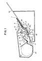
- Fig. 1 is a schematic sectional view of an image reading device as a preferred embodiment of the present invention
- Fig. 2 is a sectional view of the major parts of the embodiment
- Fig. 3 is a perspective view of the major parts of the embodiment
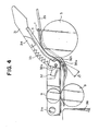
- Fig. 4 is a sectional view showing how the major parts operate
- Fig. 5 is a sectional view of the major parts as they operate when a curved document guide surface is not provided on a feed guide plate;
- Figs. 6 and 7 are sectional views of the major parts as they operate when the rotary fulcrum shaft of a transmitting guide plate is relocated;
- Fig. 8 is a sectional view of a typical prior art image communication device.
- the device has a transmitting section comprising a hopper 2 for holding a stack of documents 1, a feed roller 3 for feeding the documents 1, a transmitting guide plate 4 for guiding the upside of each document, a document-separating member 5 made of rubber or the like, a pushing member 6 for pushing the document-separating member 5, a pushing spring 7 for exerting pressure onto the pushing member 6, a feed guide plate 8, a reading roller 9 for transporting each separated document, a lamp 10 for lighting the face of each document, mirrors 11a and 11b for transmitting the reflected light, an image sensor 12 for converting the reflected light into electrical signals, and a document ejection roller 13 for ejecting documents that were read.
- a transmitting section comprising a hopper 2 for holding a stack of documents 1, a feed roller 3 for feeding the documents 1, a transmitting guide plate 4 for guiding the upside of each document, a document-separating member 5 made of rubber or the like, a pushing member 6 for pushing the document-separating member 5, a pushing spring 7 for exerting pressure onto
- the document transport path Immediately downstream of the feed roller 3 and document-separating member 5 of this device, the document transport path must not be abruptly bent toward the document-separating member 5, or the document being transported will interfere with the member 5 and can result in feed error.
- the document transport path between feed roller 3 and document ejection roller 13 is substantially straight and has an angle of 60 degrees or thereabout relative to the horizontal, as illustrated.
- the prior art image communication device also has a receiving section comprising a recording paper box 15 for holding recording paper 14, a guide 16, a recording head 17, a platen roller 18 positioned opposite to the recording head 17, a cutter 19 for cutting sheets off the recording paper 14, a recording paper ejection roller 20 for ejecting each cut sheet of the recording paper 14, and a stack guide for stacking cut sheets of the recording paper 14.
- the recording paper transport path between platen roller 18 and recording paper ejection roller 20 has an angle of 10 degrees or thereabout relative to the horizontal.
- Fig. 1 a section view thereof being shown in Fig. 1.
- the major parts of the transmitting section in the embodiment are depicted in Fig. 2.
- Fig. 2 the embodiment has on its top a hopper 30 for holding a stack of documents 1.
- the hopper 30 is inclined at about 35 degrees to the horizontal to encourage the introduction of documents into the device.
- a feed guide plate 35 At the lower end of the hopper 30 are a feed guide plate 35 for guiding the downside of documents 1 and the feed roller 3 for feeding each document.
- the support member 31 has a guide surface over which the topside of each document being fed crosswise and lengthwise from the hopper 30 is guided up to the reading roller 9.
- the support member 31 will be hereafter called the transmitting guide plate.
- the transmitting guide plate 31 is rotatably attached to a rotary fulcrum shaft 31a. In normal operation, the transmitting guide plate 31 is actuated by a spring, not shown, in the arrowed direction A and pushed as illustrated against a stopper, not shown. In case of jamming or other feed disruption, the transmitting guide plate 31 is rotated upward away from the feed roller 3 for inspection.
- the rotary fulcrum shaft 31a is located on the approximate putative extension of the document transport surface of the hopper 30. This construction prevents the transmitting guide plate 31 from rotating even if the plate 31 is pushed by the tips of documents placed on the hopper 30.
- the transmitting guide plate 31 rotatably attaches a pushing member 32 to a rotary fulcrum shaft 32a, the pushing member 32 pushing the document-separating member 5 against the feed roller 3.
- the pushing member 32 is connected to one end of a pushing spring 33 that presses the pushing member 32 against the document-separating member 5.
- the other end of the pushing spring 33 is connected to an adjusting member 34 attached to the transmitting guide plate 31.
- the adjusting member 34 is used to adjust the tension of the pushing spring 33.
- the adjusting member 34 retained by the transmitting guide plate 31 in a vertically sliding manner, is capable of adjusting the tension of the pushing spring 33 in a plurality of steps.
- the parts 31, 32, 33 and 34 constitute the assembly shown in the section view of Fig. 3.
- the pushing member 32 comprises a pushing part 32b for pushing the back of the document-separating member 5 and a document guide surface 32c located downstream of the member 5.
- the document guide surface 32c protrudes beyond an extension B of the document contact surface at the end of the document-separating member 5.
- the reading roller 9 located downstream of the document guide surface 32c is above the document transport path from the feed roller 3 and document-separating member 5 to the document guide surface 32c, i.e., above an extension C of the upstream document transport path.
- the document transport path downstream of the document guide surface 32c is inclined at an angle ⁇ to the upstream document transport path.
- the document transport path down from the feed roller 3 and document-separating member 5 is bent at the document guide surface 32c toward the pushing member 32 to approach the horizontal, the surface 32c being downstream of the document-separating member 5.
- the upstream document guide path from the feed roller 3 and document-separating member 5 to the document guide surface 32c is inclined at about 65 degrees to the horizontal, while the downstream document transport path between document guide surface 32c and reading roller 9 is inclined at about 20 degrees to the horizontal in order to reduce the overall height of the device. It follows that the angle formed by the downstream and upstream document transport paths, i.e., the angle made by extensions C and D of the respective paths, is about 135 degrees.
- the rotary fulcrum shaft 32a of the pushing member 32 is located on a bisector E of the angle formed by the document transport path that bends before and after the document guide surface 32c.
- the document guide surface 32c is provided on the pushing member 32.
- a dedicated guide means with a document guide surface may be provided apart from the pushing member.
- the embodiment as illustrated has an advantage of fewer parts to be incorporated in the device.
- the feed guide plate 35 has a document guide surface 35a concaved downward under the document guide surface 32c, i.e., under an inflection point connecting the upstream and downstream document transport paths.
- a contact-type image sensor unit 36 for reading data from each document
- a reading roller 37 for transporting each document while letting it contact the image sensor unit 36, an ejection guide 38, and the document ejection roller 13.
- the document transport path made up of these parts is located on an approximate extension of the transport path between document guide surface 32c and reading roller 9.
- the document transport path between document guide surface 32c and document ejection roller 13 is substantially straight and is inclined at about 20 degrees to the horizontal.
- the document transport path between hopper 30 and document ejection roller 13 is bent to approach the horizontal at the document guide surface 32c located immediately downstream of the document-separating member 5.
- This construction allows the overall height of the document transport path to be lower than that of the prior art device shown in Fig. 8.
- the lower path height translates into an advantage of a reduced overall height of the device.
- the embodiment also has a receiving section comprising a recording paper box 39 for holding recording paper 14, a guide 40, a recording head 17 for printing onto the recording paper 14, a platen roller 18 positioned opposite to the recording head 17, a cutter 19 for cutting sheets off the recording paper 14, a recording paper ejection roller 20, and a stack guide 21 through which cut sheets of the recording paper 14 are stacked.
- the receiving section is located above the transmitting section of the device.
- the recording paper transport path between platen roller 18 and recording paper ejection roller 20 is inclined at about 20 degrees to the horizontal, running substantially parallel to the document transport path downstream of the document-separating member 5.
- the documents 1 set in the hopper and against the feed guide plate 35 are driven by the feed roller 3 and come in contact with the document-separating member 5. There, the documents are separated one by one, each forwarded to the curved document guide surface 35a of the feed guide plate 35.
- the tip of each document 1 enters the document guide surface 35a at a small incidence angle ⁇ and is guided thereby for advance.
- the curvature of the document guide surface 35a is preferably set so that the angle between document 1 and document guide surface 35a is kept to within 30 degrees while the document is being transported. This setup prevents jamming of documents and other feed disruption.
- each document 1 proceeds at an incidence angle ⁇ of 45 degrees or more to the document guide plate 35. This can cause a document to get caught by the guide plate, resulting in jamming or other feed disruption.
- the document 1 going past the document guide surface 35a is led and forwarded by the reading roller 9.
- the document transport speed achieved by the reading roller 9 is higher than that of the feed roller 3.
- Each document 1 is being held taut while being pushed against the document guide surface 32c of the pushing member 32. Therefore the pressure onto the pushing member 32 is directed in the direction of the bisector E (see Fig. 2) of the angle formed by the bent document transport path. Because the rotary fulcrum shaft 32a of the pushing member 32 is located on this bisector, no torque is directed at the pushing member 32. Thus no change occurs in the pressure exerted by the pushing member 32 onto the document-separating member 5. This allows the documents to be separated stably one by one.
- the transmitting guide plate 31 is rotatably mounted on the rotary fulcrum shaft 31a so that any jammed document may be readily removed.
- the documents are inserted between transmitting guide plate 31 and feed roller 3.
- the tips of the documents push the transmitting guide plate 31 in parallel with the hopper 30.
- the rotary fulcrum shaft 31a is located on the approximate extension of the direction in which the documents are set on the hopper, the force for inserting the document does not rotate the transmitting guide plate 31 around the rotary fulcrum shaft 31a. Thus no trouble results from the transmitting guide plate 31 being inadvertently dislodged by documents.
- the rotary fulcrum shaft 31a of the transmitting guide plate 31 is above the extension of the direction in which the documents 1 are inserted, the force from the inserted documents 1 produces a clockwise moment in the transmitting guide 31 around the rotary fulcrum shaft 31a. This allows the pressure to increase at the point where the feed roller 3 contacts the document-separating member 5, leading to faulty paper feed or to an excess wear on the document-separating member 5. If, as shown in Fig. 6, the rotary fulcrum shaft 31a of the transmitting guide plate 31 is above the extension of the direction in which the documents 1 are inserted, the force from the inserted documents 1 produces a clockwise moment in the transmitting guide 31 around the rotary fulcrum shaft 31a. This allows the pressure to increase at the point where the feed roller 3 contacts the document-separating member 5, leading to faulty paper feed or to an excess wear on the document-separating member 5. If, as shown in Fig.
- the rotary fulcrum shaft 31a of the transmitting guide plate 31 is located under the extension of the direction in which the documents 1 are inserted, the force for inserting the documents 1 generates a counterclockwise moment in the transmitting guide plate 31 around the rotary fulcrum shaft 31a, causing the plate 31 to move away from the feed roller 3. This can result in faulty separation of the documents.
- the embodiment has its document transport path bent downstream of the feed roller and document-separating roller. This construction lowers the overall height of the device while ensuring stable feeding of documents through the device.
Landscapes
- Engineering & Computer Science (AREA)
- Multimedia (AREA)
- Signal Processing (AREA)
- Mechanical Engineering (AREA)
- Physics & Mathematics (AREA)
- General Physics & Mathematics (AREA)
- Sheets, Magazines, And Separation Thereof (AREA)
- Facsimiles In General (AREA)
Abstract
Description
- The present invention relates to a device with capabilities for reading images such as an image communication device or a copier (generically called the image reading device) and, more particularly, to an image reading device that reads images from a document while transporting it inside.
- A typical prior art image communication device has on its top a hopper on which to place a stack of documents. Below the hopper are a feed roller and a document-separating member for separating and feeding one document at a time from the stack of documents. Below the feed roller and the document-separating member are an image sensor for reading each document being transported and a document ejection roller for ejecting each document that has been read, the finished document being ejected under the device. With this type of device, bending the document transport path abruptly toward the document-separating member immediately downstream of the feed roller and document-separating member would cause the document being fed to interfere with the document-separating member and result in a feed error. The bending of the document transport path must not be acute to avoid the interference. Ordinarily, the path is substantially straight between feed roller and document ejection roller and has an angle of 60 degrees or thereabout to the horizontal.
- Because the document transport path in the transmitting section of the device, particularly the path downstream of the feed roller, has a large angle (about 60 degrees) relative to the horizontal, the path as a whole is necessarily elevated, which means the device itself becomes tall. One disadvantage of this prior art construction is that the part mounting efficiency in the device is worsened due to the device being tall.
- It is therefore an object of the present invention to provide an image reading device such as an image communication device which is low in overall height thanks to its document transport path being reduced in elevation.
- It is another object of the present invention to provide an image reading device in which the document transport path is bent so as to reduce the overall height of the device without disrupting the document-separating action performed by the feed roller and document-separating member.
- It is a further object of the present invention to provide an image reading device in which the document transport path is bent so as to reduce the overall height of the device without the need to increase the number of parts constituting the device.
- According to one aspect of the invention, there is provided an image reading device in which a pushing member for pushing the document-separating member against the feed roller has a document guide surface which is located downstream of the document-separating member and which protrudes beyond the putative extension of the document contact plane at the end of the document-separating member. Because the document guide surface supports the document, the document does not act to separate the document-separating member from the feed roller. Thus documents are separated smoothly one at a time from the stack of documents. Downstream of the document guide surface formed by the pushing member, the document transport path is bent so as to be located above the putative extension of the document transport path upstream of the document guide surface, and then stretches substantially straight. This structure reduces the elevation of the document transport path as a whole. The document guide surface guides each document as it is transported while being bent. Instead of the document guide surface, the pushing member may have an alternative guide means for guiding each document as it is transported while being bent.
- In a preferred embodiment of the invention, the pushing member is rotatably mounted around a rotation center located on a bisector of the angle formed by the document transport path before and after the document guide surface. This setup minimizes the fluctuation that may occur in the pressure of the pushing member against the document-separating member because the pressure of each document that passes the document guide surface does not exert a torque to the pushing member.
- There is preferably provided a document guide surface concaved upward below the bend of the document transport path so that the tip of each document is smoothly guided along the surface.
- Furthermore, there is preferably provided the above-mentioned pushing member being retained by a support member having a surface for guiding the topside of each document being fed from the hopper, the support member being rotatably attached to a rotary fulcrum shaft on an approximate extension of the document transport path from the hopper. Because of this construction, if the support member is pushed by the tips of documents set in the hopper, the pushing force at that time is directed to the rotary fulcrum shaft of the support member and does not rotate the member. Thus no feed error results from the change that would conventionally occur in the pressure of the document-separating member against the feed roller.
- The above and other related objects and features of the invention, as well as the novelty thereof, will clearly appear from the following description and from the accompanying drawings.
- Fig. 1 is a schematic sectional view of an image reading device as a preferred embodiment of the present invention;
- Fig. 2 is a sectional view of the major parts of the embodiment;
- Fig. 3 is a perspective view of the major parts of the embodiment;
- Fig. 4 is a sectional view showing how the major parts operate;
- Fig. 5 is a sectional view of the major parts as they operate when a curved document guide surface is not provided on a feed guide plate;
- Figs. 6 and 7 are sectional views of the major parts as they operate when the rotary fulcrum shaft of a transmitting guide plate is relocated; and
- Fig. 8 is a sectional view of a typical prior art image communication device.
- Prior to describing the preferred embodiment of the invention, a typical prior art image communication device will be described with reference to Fig. 8. As depicted, the device has a transmitting section comprising a
hopper 2 for holding a stack of documents 1, afeed roller 3 for feeding the documents 1, a transmittingguide plate 4 for guiding the upside of each document, a document-separatingmember 5 made of rubber or the like, a pushingmember 6 for pushing the document-separatingmember 5, a pushing spring 7 for exerting pressure onto the pushingmember 6, afeed guide plate 8, areading roller 9 for transporting each separated document, alamp 10 for lighting the face of each document, mirrors 11a and 11b for transmitting the reflected light, animage sensor 12 for converting the reflected light into electrical signals, and adocument ejection roller 13 for ejecting documents that were read. Immediately downstream of thefeed roller 3 and document-separatingmember 5 of this device, the document transport path must not be abruptly bent toward the document-separatingmember 5, or the document being transported will interfere with themember 5 and can result in feed error. Ordinarily, the document transport path betweenfeed roller 3 anddocument ejection roller 13 is substantially straight and has an angle of 60 degrees or thereabout relative to the horizontal, as illustrated. - The prior art image communication device also has a receiving section comprising a
recording paper box 15 for holdingrecording paper 14, aguide 16, arecording head 17, aplaten roller 18 positioned opposite to therecording head 17, acutter 19 for cutting sheets off therecording paper 14, a recordingpaper ejection roller 20 for ejecting each cut sheet of therecording paper 14, and a stack guide for stacking cut sheets of therecording paper 14. The recording paper transport path betweenplaten roller 18 and recordingpaper ejection roller 20 has an angle of 10 degrees or thereabout relative to the horizontal. - One disadvantage of the above-described prior art is that because the document transport path in the transmitting section of the device is inclined at about 60 degrees to the horizontal, the overall height of the device needs to be increased accordingly.
- This and other disadvantages of the prior art are circumvented by the preferred embodiment of the invention, a section view thereof being shown in Fig. 1. The major parts of the transmitting section in the embodiment are depicted in Fig. 2. It is to be noted that in Figs. 1 and 2 as well as in Fig. 8, like reference characters designate like or corresponding parts. Referring to Figs. 1 and 2, the embodiment has on its top a
hopper 30 for holding a stack of documents 1. Thehopper 30 is inclined at about 35 degrees to the horizontal to encourage the introduction of documents into the device. At the lower end of thehopper 30 are afeed guide plate 35 for guiding the downside of documents 1 and thefeed roller 3 for feeding each document. Above thefeed guide plate 35 and thefeed roller 3 are the document-separatingmember 5 pushed against thefeed roller 3 and asupport member 31 for retaining the document-separatingmember 5. Thesupport member 31 has a guide surface over which the topside of each document being fed crosswise and lengthwise from thehopper 30 is guided up to thereading roller 9. Thesupport member 31 will be hereafter called the transmitting guide plate. The transmittingguide plate 31 is rotatably attached to arotary fulcrum shaft 31a. In normal operation, thetransmitting guide plate 31 is actuated by a spring, not shown, in the arrowed direction A and pushed as illustrated against a stopper, not shown. In case of jamming or other feed disruption, the transmittingguide plate 31 is rotated upward away from thefeed roller 3 for inspection. Therotary fulcrum shaft 31a is located on the approximate putative extension of the document transport surface of thehopper 30. This construction prevents the transmittingguide plate 31 from rotating even if theplate 31 is pushed by the tips of documents placed on thehopper 30. - The transmitting
guide plate 31 rotatably attaches a pushingmember 32 to arotary fulcrum shaft 32a, the pushingmember 32 pushing the document-separatingmember 5 against thefeed roller 3. The pushingmember 32 is connected to one end of a pushingspring 33 that presses the pushingmember 32 against the document-separatingmember 5. The other end of the pushingspring 33 is connected to an adjustingmember 34 attached to the transmittingguide plate 31. The adjustingmember 34 is used to adjust the tension of the pushingspring 33. Specifically the adjustingmember 34, retained by the transmittingguide plate 31 in a vertically sliding manner, is capable of adjusting the tension of the pushingspring 33 in a plurality of steps. Theparts - Referring to Fig. 2, the pushing
member 32 comprises a pushingpart 32b for pushing the back of the document-separatingmember 5 and adocument guide surface 32c located downstream of themember 5. Thedocument guide surface 32c protrudes beyond an extension B of the document contact surface at the end of the document-separatingmember 5. The readingroller 9 located downstream of thedocument guide surface 32c is above the document transport path from thefeed roller 3 and document-separatingmember 5 to thedocument guide surface 32c, i.e., above an extension C of the upstream document transport path. Thus the document transport path downstream of thedocument guide surface 32c is inclined at an angle α to the upstream document transport path. In other words, the document transport path down from thefeed roller 3 and document-separatingmember 5 is bent at thedocument guide surface 32c toward the pushingmember 32 to approach the horizontal, thesurface 32c being downstream of the document-separatingmember 5. The upstream document guide path from thefeed roller 3 and document-separatingmember 5 to thedocument guide surface 32c is inclined at about 65 degrees to the horizontal, while the downstream document transport path betweendocument guide surface 32c and readingroller 9 is inclined at about 20 degrees to the horizontal in order to reduce the overall height of the device. It follows that the angle formed by the downstream and upstream document transport paths, i.e., the angle made by extensions C and D of the respective paths, is about 135 degrees. Therotary fulcrum shaft 32a of the pushingmember 32 is located on a bisector E of the angle formed by the document transport path that bends before and after thedocument guide surface 32c. With this arrangement, when a document passes as it bends over thedocument guide surface 32c, the tension of the document applied to thesurface 32c is in fact directed to therotary fulcrum shaft 32a. That is, one benefit of this arrangement is that the pushingmember 32 is not torqued by passing documents, with the result that no change takes place in the pressure against the document-separatingmember 5. Because thedocument guide surface 32c protrudes beyond the extension B of the document contact surface at the end of the document-separatingmember 5, themember 5 is not pushed upward by documents. With the pressure against the document-separatingmember 5 held constant, the mechanical area in which documents are separated one at a time is not reduced. In this embodiment, thedocument guide surface 32c is provided on the pushingmember 32. Alternatively, a dedicated guide means with a document guide surface may be provided apart from the pushing member. However, the embodiment as illustrated has an advantage of fewer parts to be incorporated in the device. - The
feed guide plate 35 has adocument guide surface 35a concaved downward under thedocument guide surface 32c, i.e., under an inflection point connecting the upstream and downstream document transport paths. - Referring again to Fig. 1, downstream of the reading
roller 9 are a contact-typeimage sensor unit 36 for reading data from each document, a readingroller 37 for transporting each document while letting it contact theimage sensor unit 36, anejection guide 38, and thedocument ejection roller 13. The document transport path made up of these parts is located on an approximate extension of the transport path betweendocument guide surface 32c and readingroller 9. Thus the document transport path betweendocument guide surface 32c anddocument ejection roller 13 is substantially straight and is inclined at about 20 degrees to the horizontal. As described, the document transport path betweenhopper 30 anddocument ejection roller 13 is bent to approach the horizontal at thedocument guide surface 32c located immediately downstream of the document-separatingmember 5. This construction allows the overall height of the document transport path to be lower than that of the prior art device shown in Fig. 8. The lower path height translates into an advantage of a reduced overall height of the device. - The embodiment also has a receiving section comprising a
recording paper box 39 for holdingrecording paper 14, aguide 40, arecording head 17 for printing onto therecording paper 14, aplaten roller 18 positioned opposite to therecording head 17, acutter 19 for cutting sheets off therecording paper 14, a recordingpaper ejection roller 20, and astack guide 21 through which cut sheets of therecording paper 14 are stacked. The receiving section is located above the transmitting section of the device. The recording paper transport path betweenplaten roller 18 and recordingpaper ejection roller 20 is inclined at about 20 degrees to the horizontal, running substantially parallel to the document transport path downstream of the document-separatingmember 5. - Below is a description of how the documents 1 are transported through the transmitting section of the embodiment. Referring to Fig. 4, the documents 1 set in the hopper and against the
feed guide plate 35 are driven by thefeed roller 3 and come in contact with the document-separatingmember 5. There, the documents are separated one by one, each forwarded to the curveddocument guide surface 35a of thefeed guide plate 35. The tip of each document 1 enters thedocument guide surface 35a at a small incidence angle β and is guided thereby for advance. At this point, the curvature of thedocument guide surface 35a is preferably set so that the angle between document 1 and documentguide surface 35a is kept to within 30 degrees while the document is being transported. This setup prevents jamming of documents and other feed disruption. - If the curved
document guide surface 35a is not provided, as in conventional setups, on thefeed guide plate 35, thefeed guide plate 35 is shaped as depicted in Fig. 5. In this case, each document 1 proceeds at an incidence angle δ of 45 degrees or more to thedocument guide plate 35. This can cause a document to get caught by the guide plate, resulting in jamming or other feed disruption. - Referring again to Fig. 4, the document 1 going past the
document guide surface 35a is led and forwarded by the readingroller 9. At this point, in Fig. 2, the document transport speed achieved by the readingroller 9 is higher than that of thefeed roller 3. Each document 1 is being held taut while being pushed against thedocument guide surface 32c of the pushingmember 32. Therefore the pressure onto the pushingmember 32 is directed in the direction of the bisector E (see Fig. 2) of the angle formed by the bent document transport path. Because therotary fulcrum shaft 32a of the pushingmember 32 is located on this bisector, no torque is directed at the pushingmember 32. Thus no change occurs in the pressure exerted by the pushingmember 32 onto the document-separatingmember 5. This allows the documents to be separated stably one by one. Because thedocument guide surface 32c of the pushingmember 32 protrudes beyond the extension B of the document guide surface at the downstream end of the document-separatingmember 5, there is no possibility of the document-separatingmember 5 getting pushed up by any document 1 resulting in fluctuations in the pushing force or in a reduction of the mechanical area for document separation. This feature also contributes to having the documents separated stably one by one. - How the transmitting
guide plate 31 works will now be described by referring again to Fig. 2. The transmittingguide plate 31 is rotatably mounted on therotary fulcrum shaft 31a so that any jammed document may be readily removed. When documents are set on thehopper 30, the documents are inserted between transmittingguide plate 31 andfeed roller 3. At this point, the tips of the documents push the transmittingguide plate 31 in parallel with thehopper 30. But because the therotary fulcrum shaft 31a is located on the approximate extension of the direction in which the documents are set on the hopper, the force for inserting the document does not rotate the transmittingguide plate 31 around therotary fulcrum shaft 31a. Thus no trouble results from the transmittingguide plate 31 being inadvertently dislodged by documents. - If, as shown in Fig. 6, the
rotary fulcrum shaft 31a of the transmittingguide plate 31 is above the extension of the direction in which the documents 1 are inserted, the force from the inserted documents 1 produces a clockwise moment in the transmittingguide 31 around therotary fulcrum shaft 31a. This allows the pressure to increase at the point where thefeed roller 3 contacts the document-separatingmember 5, leading to faulty paper feed or to an excess wear on the document-separatingmember 5. If, as shown in Fig. 7, therotary fulcrum shaft 31a of the transmittingguide plate 31 is located under the extension of the direction in which the documents 1 are inserted, the force for inserting the documents 1 generates a counterclockwise moment in the transmittingguide plate 31 around therotary fulcrum shaft 31a, causing theplate 31 to move away from thefeed roller 3. This can result in faulty separation of the documents. These problems are solved by the embodiment in which therotary fulcrum shaft 31a of the transmittingguide plate 31 is suitably located where it is. - As described, the embodiment has its document transport path bent downstream of the feed roller and document-separating roller. This construction lowers the overall height of the device while ensuring stable feeding of documents through the device.
- While the preferred embodiment of the invention has been described using specific terms, such description is for illustrative purposes only, and it is to be understood that changes and variations may be made without departing from the spirit or scope of the following claims.
Claims (14)
- An image reading device comprising:
a feed roller;
a document-separating member located to contact said feed roller so as to ensure the feeding one at a time of documents inserted between said feed roller and said member;
a support member for supporting said document-separating member; and
a pushing member attached to said support member so as to push said document-separating member against said feed roller;
wherein said pushing member has a document guide surface located downstream of said document-separating member, said document guide surface protruding beyond an extension of the document contact surface at the downstream end of said document-separating member. - An image reading device according to claim 1, wherein a document transport path between said feed roller and said document guide surface of said pushing member is inclined downward, said document transport path downstream of said document guide surface being bent so as to be located above an extension of said document transport path upstream of said document guide surface, said downstream document transport path being extended substantially straight.
- An image reading device according to claim 2, wherein said pushing member is rotatably attached to said support member, a rotary fulcrum point of said pushing member being located on a bisector of the angle formed by said two portions of the document transport path upstream and downstream of said document guide surface.
- An image reading device according to any of claims 2 and 3, further comprising a document guide surface concaved downward under the document guide surface of said pushing member.
- An image reading device according to any of claims 1 through 3, further comprising a hopper for supplying documents to said feed roller, said support member having a guide surface for guiding each document fed from said hopper, said support member being rotatably attached to a rotary fulcrum point located on an approximate extension of a document transport surface of said hopper.
- An image reading device according to claim 4, further comprising a hopper for supplying documents to said feed roller, said support member having a guide surface for guiding each document fed from said hopper, said support member being rotatably attached to a rotary fulcrum point located on an approximate extension of a document transport surface of said hopper.
- An image reading device comprising:
a feed roller;
a document-separating member located to contact said feed roller so as to ensure the feeding one at a time of documents inserted between said feed roller and said member;
a support member for supporting said document-separating member;
a pushing member which is rotatably attached to said support member so as to push said document-separating member against said feed roller and which has a document guide surface located downstream of said document-separating member; and
a means for constituting a document transport path bent at said document guide surface of said pushing member;
wherein a rotary fulcrum point of said pushing member is located on a bisector of the angle formed by two portions of said document transport path, one portion being upstream of said document guide surface and the other being downstream thereof. - An image reading device comprising:
a feed roller;
a document-separating member located to contact said feed roller so as to ensure the feeding one at a time of documents inserted between said feed roller and said member;
a means for constituting an upstream document transport path inclined downward downstream of said feed roller and said document-separating means, said path stretching in a substantially straight manner;
a means for constituting a downstream document transport path which follows said upstream document transport path and which is bent to be located above an extension of said upstream document transport path, said downstream document transport path stretching in a substantially straight manner; and
a document guide surface which is located under an inflection point connecting said upstream document transport path with said downstream document transport path and which is concaved upward. - An image reading device comprising:
a feed roller;
a document-separating member located to contact said feed roller so as to ensure the feeding one at a time of documents inserted between said feed roller and said member;
a means for constituting an upstream document transport path inclined downward downstream of said feed roller and said document-separating means, said path stretching in a substantially straight manner;
a means for constituting a downstream document transport path which follows said upstream document transport path and which is bent from said upstream document transport path toward the horizontal, said downstream document transport path stretching in a substantially straight manner; and
a guide means for guiding each document from said upstream document transport path to said downstream document transport path, said means being located above an inflection point connecting said upstream and downstream document transport paths. - An image reading device comprising:
a hopper on which to set a stack of documents;
a feed roller for feeding said documents from said hopper;
a document-separating member located to contact said feed roller so as to ensure the feeding one at a time of documents inserted between said feed roller and said member;
a pushing member for pushing said document-separating member against said feed roller; and
a support member which retains said pushing member and which has a guide surface for guiding the topside of each document fed from said hopper;
wherein said support member is rotatably attached to a rotary fulcrum point located on an approximate extension of a document transport surface of said hopper. - An image communication device comprising:
a feed roller;
a document-separating member located to contact said feed roller so as to ensure the feeding one at a time of documents inserted between said feed roller and said member;
a support member for supporting said document-separating member; and
a pushing member attached to said support member so as to push said document-separating member against said feed roller;
wherein said pushing member has a document guide surface located downstream of said document-separating member, said document guide surface protruding beyond an extension of the document contact surface at the downstream end of said document-separating member. - An image communication device according to claim 11, wherein an upstream document transport path from said feed roller to said document guide surface of said pushing member is inclined downward, said upstream document transport path being followed by a downstream document guide path downstream of said document guide surface, said downstream document path being so bent as to be located above an extension of said upstream document transport path while stretching in a substantially straight manner, said pushing member being rotatably attached to said support member, a rotary fulcrum point of said pushing member being located on a bisector of the angle formed by said upstream and downstream document transport paths.
- An image communication device according to claim 12, further comprising a document guide surface concaved upward under the document guide surface of said pushing member.
- An image communication device according to any of claims 11 through 13, further comprising a hopper from which to supply a stack of documents to said feed roller, said support member having a guide surface for guiding each document supplied from said hopper, said support member being rotatably retained around a rotary fulcrum point located on an approximate extension of a document transport surface of said hopper.
Applications Claiming Priority (2)
| Application Number | Priority Date | Filing Date | Title |
|---|---|---|---|
| JP327916/89 | 1989-12-18 | ||
| JP1327916A JPH03192039A (en) | 1989-12-18 | 1989-12-18 | Image reading-out device |
Publications (3)
| Publication Number | Publication Date |
|---|---|
| EP0434285A2 true EP0434285A2 (en) | 1991-06-26 |
| EP0434285A3 EP0434285A3 (en) | 1992-07-08 |
| EP0434285B1 EP0434285B1 (en) | 1996-03-27 |
Family
ID=18204431
Family Applications (1)
| Application Number | Title | Priority Date | Filing Date |
|---|---|---|---|
| EP90313474A Expired - Lifetime EP0434285B1 (en) | 1989-12-18 | 1990-12-11 | Image reading device |
Country Status (4)
| Country | Link |
|---|---|
| US (1) | US5102115A (en) |
| EP (1) | EP0434285B1 (en) |
| JP (1) | JPH03192039A (en) |
| DE (1) | DE69026220T2 (en) |
Cited By (4)
| Publication number | Priority date | Publication date | Assignee | Title |
|---|---|---|---|---|
| EP0511004A3 (en) * | 1991-04-26 | 1993-08-18 | Canon Kabushiki Kaisha | Original image reading device and image information processing apparatus having the same |
| FR2695591A1 (en) * | 1992-09-15 | 1994-03-18 | Swatch Ag | Fax machine with a device to facilitate the reloading of paper. |
| EP0563884A3 (en) * | 1992-03-31 | 1994-09-28 | Toshiba Kk | An image forming apparatus having a filing section and a printing section |
| WO1996037428A1 (en) * | 1995-05-23 | 1996-11-28 | Philips Electronics N.V. | Apparatus for consecutively processing sheet-like record carriers |
Families Citing this family (12)
| Publication number | Priority date | Publication date | Assignee | Title |
|---|---|---|---|---|
| DE69116749T2 (en) * | 1990-07-06 | 1996-09-19 | Canon Kk | Sheet feeder |
| NL9100891A (en) * | 1991-05-23 | 1992-12-16 | Hadewe Bv | DEVICE FOR DELIVERING FLAT OBJECTS CONTAINING ONE OR MORE LAYERS. |
| JPH05201572A (en) * | 1991-07-29 | 1993-08-10 | Riso Kagaku Corp | Paper separating type paper feeding device |
| JPH0632478A (en) * | 1992-07-13 | 1994-02-08 | Mita Ind Co Ltd | Automatic paper feeding mechanism |
| JP2571311Y2 (en) * | 1992-09-24 | 1998-05-18 | ブラザー工業株式会社 | Paper feeder |
| JP3406395B2 (en) * | 1994-08-31 | 2003-05-12 | 理想科学工業株式会社 | Paper feeder |
| US5718424A (en) * | 1995-02-01 | 1998-02-17 | Canon Kabushiki Kaisha | Sheet feeding device having a separating and prestressing device |
| FR2729938A1 (en) * | 1995-02-01 | 1996-08-02 | Canon Kk | SHEET FEEDING DEVICE HAVING A MOBILE SUPPORT MEDIUM COOPERATING SIDE GUIDANCE ALONG A TRANSFER PATH AND SOLICITED BY A THRUST MEANS |
| US5996989A (en) * | 1997-05-02 | 1999-12-07 | Lexmark International, Inc. | Sheet separator friction pad |
| DE10121814A1 (en) * | 2000-05-17 | 2001-11-22 | Heidelberger Druckmasch Ag | Rotatable pressure carrier guide |
| TWI361755B (en) * | 2009-06-16 | 2012-04-11 | Kinpo Elect Inc | Paper feeding device |
| JP5799779B2 (en) * | 2011-11-30 | 2015-10-28 | ブラザー工業株式会社 | Sheet transport device |
Family Cites Families (9)
| Publication number | Priority date | Publication date | Assignee | Title |
|---|---|---|---|---|
| US2363357A (en) * | 1941-02-10 | 1944-11-21 | Anah K Post | Sheet feed |
| GB1087786A (en) * | 1965-05-06 | 1967-10-18 | Rank Xerox Ltd | Document feeder |
| US4306713A (en) * | 1980-04-25 | 1981-12-22 | International Business Machines Corporation | Document feeder |
| US4674737A (en) * | 1983-09-14 | 1987-06-23 | Ricoh Company, Ltd. | Automatic sheet feeding device |
| JPS60117866A (en) * | 1983-11-29 | 1985-06-25 | Toshiba Corp | Picture information reader |
| EP0204227B1 (en) * | 1985-05-24 | 1990-09-12 | Mita Industrial Co. Ltd. | Paper feeding device |
| JPS6357446A (en) * | 1986-08-27 | 1988-03-12 | Canon Inc | Paper feed device |
| JPS63272728A (en) * | 1987-04-30 | 1988-11-10 | Matsushita Graphic Commun Syst Inc | Automatic paper feeder |
| JPH02178135A (en) * | 1988-12-28 | 1990-07-11 | Nippon Seimitsu Kogyo Kk | Paper feeder |
-
1989
- 1989-12-18 JP JP1327916A patent/JPH03192039A/en active Pending
-
1990
- 1990-12-11 DE DE69026220T patent/DE69026220T2/en not_active Expired - Fee Related
- 1990-12-11 EP EP90313474A patent/EP0434285B1/en not_active Expired - Lifetime
- 1990-12-12 US US07/626,301 patent/US5102115A/en not_active Expired - Fee Related
Cited By (7)
| Publication number | Priority date | Publication date | Assignee | Title |
|---|---|---|---|---|
| EP0511004A3 (en) * | 1991-04-26 | 1993-08-18 | Canon Kabushiki Kaisha | Original image reading device and image information processing apparatus having the same |
| US5526141A (en) * | 1991-04-26 | 1996-06-11 | Canon Kabushiki Kaisha | Original image reading apparatus having device for conveying an original at a position deviated from an original reading position of a contact-type reading sensor |
| EP0563884A3 (en) * | 1992-03-31 | 1994-09-28 | Toshiba Kk | An image forming apparatus having a filing section and a printing section |
| FR2695591A1 (en) * | 1992-09-15 | 1994-03-18 | Swatch Ag | Fax machine with a device to facilitate the reloading of paper. |
| EP0588205A1 (en) * | 1992-09-15 | 1994-03-23 | Swatch Ag | Facsimile apparatus with device for simplified paper reloading |
| WO1996037428A1 (en) * | 1995-05-23 | 1996-11-28 | Philips Electronics N.V. | Apparatus for consecutively processing sheet-like record carriers |
| US5718425A (en) * | 1995-05-23 | 1998-02-17 | U.S. Philips Corporation | Apparatus for consecutively processing sheet-like record carriers |
Also Published As
| Publication number | Publication date |
|---|---|
| US5102115A (en) | 1992-04-07 |
| JPH03192039A (en) | 1991-08-21 |
| DE69026220T2 (en) | 1996-10-10 |
| EP0434285B1 (en) | 1996-03-27 |
| DE69026220D1 (en) | 1996-05-02 |
| EP0434285A3 (en) | 1992-07-08 |
Similar Documents
| Publication | Publication Date | Title |
|---|---|---|
| US5102115A (en) | Image reading device | |
| JP2560315B2 (en) | Automatic paper feeder | |
| US6659450B2 (en) | Sheet feeding apparatus and automatic document using the same | |
| US7588246B2 (en) | Paper transportation device with adjustable separating pad holder | |
| US6824131B2 (en) | Method and apparatus for image forming and effectively performing sheet feeding using a sheet feed roller and a tilt member | |
| US7980549B2 (en) | Document feeder and image forming device | |
| US5219156A (en) | Automatic orgiinal sheet feeding apparatus | |
| JP3680312B2 (en) | Paper feeder | |
| USRE43682E1 (en) | Pressure-adjustable mechanism for paper feeding roller of automatic paper feeder | |
| US6956679B2 (en) | Paper feeder apparatus and facsimile apparatus | |
| US7455294B2 (en) | Paper-releasing mechanism | |
| US10245859B1 (en) | Paper feeding mechanism | |
| US8146912B2 (en) | Recording media separating device and recording apparatus | |
| US20130193635A1 (en) | Feeding apparatus | |
| JP4784958B2 (en) | Device having guide means for guiding a scanning record carrier | |
| JPS63225044A (en) | Automatic paper feeder | |
| KR100186594B1 (en) | Automatic paper sensing system of inkjet printer | |
| JP2000072266A (en) | Paper feeder | |
| KR200362498Y1 (en) | Apparatus for arranging rear part of paper | |
| JP2617796B2 (en) | Document feeder | |
| JPH04101939A (en) | Automatic paper feeder | |
| JPH06115748A (en) | Automatic paper feeder | |
| JP2006117331A (en) | Paper feeder | |
| US7556253B2 (en) | Auto document feeder | |
| JP2008024398A (en) | Paper insertion mechanism of paper feeder |
Legal Events
| Date | Code | Title | Description |
|---|---|---|---|
| PUAI | Public reference made under article 153(3) epc to a published international application that has entered the european phase |
Free format text: ORIGINAL CODE: 0009012 |
|
| AK | Designated contracting states |
Kind code of ref document: A2 Designated state(s): DE FR GB |
|
| RIN1 | Information on inventor provided before grant (corrected) |
Inventor name: YAMADA, HIROYUKI Inventor name: KUMANO, TOSHIHIRO Inventor name: SATO, MASANORI Inventor name: ISHII, YUJI Inventor name: TAKAMIZAWA, SHIRO |
|
| PUAL | Search report despatched |
Free format text: ORIGINAL CODE: 0009013 |
|
| AK | Designated contracting states |
Kind code of ref document: A3 Designated state(s): DE FR GB |
|
| 17P | Request for examination filed |
Effective date: 19930105 |
|
| 17Q | First examination report despatched |
Effective date: 19941123 |
|
| GRAH | Despatch of communication of intention to grant a patent |
Free format text: ORIGINAL CODE: EPIDOS IGRA |
|
| GRAA | (expected) grant |
Free format text: ORIGINAL CODE: 0009210 |
|
| AK | Designated contracting states |
Kind code of ref document: B1 Designated state(s): DE FR GB |
|
| REF | Corresponds to: |
Ref document number: 69026220 Country of ref document: DE Date of ref document: 19960502 |
|
| ET | Fr: translation filed | ||
| PLBE | No opposition filed within time limit |
Free format text: ORIGINAL CODE: 0009261 |
|
| STAA | Information on the status of an ep patent application or granted ep patent |
Free format text: STATUS: NO OPPOSITION FILED WITHIN TIME LIMIT |
|
| 26N | No opposition filed | ||
| PGFP | Annual fee paid to national office [announced via postgrant information from national office to epo] |
Ref country code: DE Payment date: 20001204 Year of fee payment: 11 |
|
| PGFP | Annual fee paid to national office [announced via postgrant information from national office to epo] |
Ref country code: GB Payment date: 20001206 Year of fee payment: 11 |
|
| PGFP | Annual fee paid to national office [announced via postgrant information from national office to epo] |
Ref country code: FR Payment date: 20001212 Year of fee payment: 11 |
|
| PG25 | Lapsed in a contracting state [announced via postgrant information from national office to epo] |
Ref country code: GB Free format text: LAPSE BECAUSE OF NON-PAYMENT OF DUE FEES Effective date: 20011211 |
|
| REG | Reference to a national code |
Ref country code: GB Ref legal event code: IF02 |
|
| PG25 | Lapsed in a contracting state [announced via postgrant information from national office to epo] |
Ref country code: DE Free format text: LAPSE BECAUSE OF NON-PAYMENT OF DUE FEES Effective date: 20020702 |
|
| GBPC | Gb: european patent ceased through non-payment of renewal fee |
Effective date: 20011211 |
|
| PG25 | Lapsed in a contracting state [announced via postgrant information from national office to epo] |
Ref country code: FR Free format text: LAPSE BECAUSE OF NON-PAYMENT OF DUE FEES Effective date: 20020830 |
|
| REG | Reference to a national code |
Ref country code: FR Ref legal event code: ST |