EP0434431A1 - Verfahren zur Abschirmung eines Kabeleingangs, Einrichtung zur Verbindung an einem Kabel und Klemme - Google Patents
Verfahren zur Abschirmung eines Kabeleingangs, Einrichtung zur Verbindung an einem Kabel und Klemme Download PDFInfo
- Publication number
- EP0434431A1 EP0434431A1 EP90314032A EP90314032A EP0434431A1 EP 0434431 A1 EP0434431 A1 EP 0434431A1 EP 90314032 A EP90314032 A EP 90314032A EP 90314032 A EP90314032 A EP 90314032A EP 0434431 A1 EP0434431 A1 EP 0434431A1
- Authority
- EP
- European Patent Office
- Prior art keywords
- connector
- cable
- elements
- clamping
- side wall
- Prior art date
- Legal status (The legal status is an assumption and is not a legal conclusion. Google has not performed a legal analysis and makes no representation as to the accuracy of the status listed.)
- Withdrawn
Links
- 238000000034 method Methods 0.000 title claims description 10
- 239000000463 material Substances 0.000 description 11
- 229920003023 plastic Polymers 0.000 description 10
- 239000004033 plastic Substances 0.000 description 10
- PXHVJJICTQNCMI-UHFFFAOYSA-N Nickel Chemical compound [Ni] PXHVJJICTQNCMI-UHFFFAOYSA-N 0.000 description 8
- 238000009954 braiding Methods 0.000 description 5
- RYGMFSIKBFXOCR-UHFFFAOYSA-N Copper Chemical compound [Cu] RYGMFSIKBFXOCR-UHFFFAOYSA-N 0.000 description 4
- 238000010276 construction Methods 0.000 description 4
- 229910052802 copper Inorganic materials 0.000 description 4
- 239000010949 copper Substances 0.000 description 4
- 239000002184 metal Substances 0.000 description 4
- 229910052751 metal Inorganic materials 0.000 description 4
- 229910052759 nickel Inorganic materials 0.000 description 4
- 238000007493 shaping process Methods 0.000 description 2
- 230000033228 biological regulation Effects 0.000 description 1
- 238000002788 crimping Methods 0.000 description 1
- -1 for example Substances 0.000 description 1
- 238000012423 maintenance Methods 0.000 description 1
- 238000004519 manufacturing process Methods 0.000 description 1
- 238000012986 modification Methods 0.000 description 1
- 230000004048 modification Effects 0.000 description 1
- 238000007747 plating Methods 0.000 description 1
- 230000001629 suppression Effects 0.000 description 1
Images



Classifications
-
- H—ELECTRICITY
- H01—ELECTRIC ELEMENTS
- H01R—ELECTRICALLY-CONDUCTIVE CONNECTIONS; STRUCTURAL ASSOCIATIONS OF A PLURALITY OF MUTUALLY-INSULATED ELECTRICAL CONNECTING ELEMENTS; COUPLING DEVICES; CURRENT COLLECTORS
- H01R13/00—Details of coupling devices of the kinds covered by groups H01R12/70 or H01R24/00 - H01R33/00
- H01R13/648—Protective earth or shield arrangements on coupling devices, e.g. anti-static shielding
- H01R13/658—High frequency shielding arrangements, e.g. against EMI [Electro-Magnetic Interference] or EMP [Electro-Magnetic Pulse]
- H01R13/6591—Specific features or arrangements of connection of shield to conductive members
- H01R13/6592—Specific features or arrangements of connection of shield to conductive members the conductive member being a shielded cable
- H01R13/6593—Specific features or arrangements of connection of shield to conductive members the conductive member being a shielded cable the shield being composed of different pieces
-
- H—ELECTRICITY
- H01—ELECTRIC ELEMENTS
- H01R—ELECTRICALLY-CONDUCTIVE CONNECTIONS; STRUCTURAL ASSOCIATIONS OF A PLURALITY OF MUTUALLY-INSULATED ELECTRICAL CONNECTING ELEMENTS; COUPLING DEVICES; CURRENT COLLECTORS
- H01R13/00—Details of coupling devices of the kinds covered by groups H01R12/70 or H01R24/00 - H01R33/00
- H01R13/46—Bases; Cases
- H01R13/514—Bases; Cases composed as a modular blocks or assembly, i.e. composed of co-operating parts provided with contact members or holding contact members between them
Definitions
- the present invention relates generally to connectors for electric cables.
- cables to the equipment function as aerials, and because of this, rf interference from cables is increasingly prevented by providing a conductive braiding around cables within their plastics material sheaths.
- the cables are connected to respective connectors, usually D-connectors made of a plastics material.
- D-connectors made of a plastics material.
- the plastics material of the D-connectors has been plated with metal, for example, copper or nickel to provide shielding for the connectors.
- metal for example, copper or nickel.
- a common technique involves crimping a ferrule onto a length of exposed braiding of the cable near to its end. The cable is then positioned such that the ferrule extends into or abuts the cable entry of the connector and is electrically connected to the connector. Then a cover is provided around the ferrule and the cable entry of the connector to fasten the structure into place.
- the present invention seeks to provide in a simple manner reliable shielding at the cable entry of a connector.
- a method of shielding a cable entry in a connector comprising the steps of clamping a conductive clamp member onto part of a cable to extend through said cable entry, and locating said clamp member within said connector such that the clamp member restricts the cable entry, wherein the clamp member is arranged to be in electrical contact with said connector and said cable.
- said clamp member has a releasable clamping action which aids in the original shielding of the cable entry, but also facilitates access to the cable and/or to the connector for maintenance and the like.
- the present invention also extends to apparatus for connection to a cable, said apparatus comprising a connector housing having a cable entry, shielding means for shielding the cable entry when a cable extends therethrough, said shielding means comprising a conductive clamp member for clamping onto the cable, and locating means provided within said connector housing adjacent to said cable entry for receiving and locating said clamp member such that it restricts the cable entry.
- said locating means is formed on said connector housing, and comprises a shaped recess defined within said housing and arranged to locate said clamp member such that it extends across said cable entry.
- said clamp member comprises two interengageable clamping parts which can be arranged in clamping engagement in a number of different relative positions.
- the clamping parts are movable progressively towards one another.
- a first one of the clamping parts has a guide member
- a second one of the clamping parts has a member arranged for movement along said guide member to progressively vary the relative position of the two clamping parts.
- Engaging means are provided to selectively engage said two clamping parts in their various relative positions.
- said engaging means comprises a plurality of engaging members on one of the clamping parts which are selectively engageable, in dependence upon the relative position of the two clamping parts, with co-operable means on the other of the clamping parts.
- the plurality of engaging members are provided on said member of said second clamping part, and the co-operable means are provided on said guide member of the first clamping part.
- said member of the second clamping part has a plurality of projections arranged to selectively engage a rib provided on the guide member.
- said clamp member comprises two interengageable clamping parts arrangeable in clamping engagement in a plurality of different clamping positions, wherein a first one of said clamping parts has two spaced, substantially parallel channel members which define therebetween a substantially U-shaped opening, and the second one of said clamping parts has two spaced, substantially parallel legs which define therebetween a substantially U-shaped opening, and wherein each leg of said second clamping part is receivable within a respective channel member of said first clamping part such that said two U-shaped openings face and together define a cable clamping hole, and wherein each said leg is movable along the respective channel member whereby the dimensions of said hole are variable.
- a clamp member for shielding a cable entry in a connector, said clamp member comprising two interengageable clamping parts arrangeable in clamping engagement in a plurality of different clamping positions, wherein a first one of said clamping parts has two spaced, substantially parallel channel members which define therebetween a substantially U-shaped opening, and the second one of said clamping parts has two spaced, substantially parallel legs which define therebetween a substantially U-shaped opening, and wherein each leg of said second clamping part is receivable within a respective channel member of said first clamping part such that said two U-shaped openings face and together define a cable clamping hole, and wherein each said leg is movable along the respective channel member whereby the dimensions of said hole are variable.
- Engaging means are provided to selectively engage each leg in a predetermined relative position within the respective channel member.
- the engaging means may comprise a plurality of engaging members carried on one of each leg or the respective channel member, the engaging members being selectively engageable with co-operable means provided on the other of the channel member and its respective leg.
- the plurality of engaging members are provided on each leg, and the co-operable means are provided in the respective channel members.
- the engaging members comprise a series of teeth or other projections arranged along the outer surface of each of the legs.
- the co-operable means comprise one or more ribs formed within each channel member.
- D-connectors are used in a large number of applications. Traditionally, they are made in five different sizes. Commonly, larger connectors having 25 pins, and smaller connectors having 15 pins are used.
- the basic connector has a housing made in two halves held together to hold a connector block at its front and to define a cable entry at its rear.
- a connector for an electrical cable which is formed from five or six modular elements connected together.
- the modular elements are designed and shaped such that standard connectors and specialist connectors can be fabricated at will by an appropriate choice of modular elements.
- the modular elements preferably include two different side wall elements.
- the first version of a side wall element comprises a substantially planar, rectangular, side wall having an inwardly extending lip formed on each of its two longest edges. When two of these side wall elements are connected to be opposed and spaced from one another, the lips at each edge thereof can be used to locate a connector block.
- the alternative side wall element is substantially identical to the first version except that one of said lips is replaced by an inwardly extending wall member provided substantially centrally with a half cylindrical flange for defining a cable entry.
- the modular elements also comprise two different types of end wall element.
- the first type of end wall element comprises a substantially planar end wall block.
- the alternative end wall is hollow and has a cable entry formed to extend therethrough.
- the cable entry is arranged to carry a cable clamp.
- the first front or rear wall element type is a substantially planar blanking plate.
- the second type of front or rear wall element comprises a substantially conventional connector block having a perimetral plate whose outer periphery is substantially identical to that of a planar blanking plate.
- Combinations of the modular elements can be connected together to define a connector. Where the side wall elements form integral cable entries, only five modular elements are required. In other cases six modular elements are generally needed.
- a connector for an electrical cable comprising a connector housing formed of two substantially identical side wall elements, and two end wall elements arranged spaced and opposite to one another, and connected to said side wall elements to maintain said side wall elements spaced and substantially parallel to one another, said connector housing also having spaced and opposed front and rear wall elements, at least one of said front and rear wall elements being defined by a connector block connected to said end wall elements and located by said side wall elements.
- the side wall elements, end wall elements and front and rear wall elements form modular elements which are designed and shaped such that standard connectors and specialist connectors can be fabricated at will by an appropriate choice of modular elements.
- the modular elements preferably include two different side wall elements.
- the first version of a side wall element comprises a substantially planar rectangular, side wall having an inwardly extending lip formed on each of its two longest edges. When two of these side wall elements are connected opposed and spaced from one another, the lips at each edge thereof can be used to locate a connector block.
- the alternative side wall element is substantially identical to the first version except that one of said lips is replaced by an inwardly extending wall member provided substantially centrally with a half cylindrical flange for defining a cable entry.
- the modular elements also comprise two different types of end wall element.
- the first type of end wall element comprises a substantially planar end wall block.
- the alternative end wall is hollow and has a cable entry formed to extend therethrough.
- the cable entry is arranged to carry a cable clamp.
- the first front or rear wall element type is a substantially planar blanking plate.
- the second type of front or rear wall element comprises a connector block having a perimetral plate whose outer periphery is substantially identical to that of a planar blanking plate.
- Combinations of the modular elements can be connected together to define a connector. Where the side wall elements form integral cable entries only five modular elements are required. In other cases six modular elements are generally needed.
- the modular connector defined above may be made of any appropriate material.
- the modular elements may be formed of plastics material and the individual elements can be connected by screws, pins and the like as appropriate.
- each end wall element is preferably constructed to have a chamfered or ridged end face with which an edge of each side wall element abuts whereby no gap is defined between an end wall and an adjacent side wall.
- a modular connector as defined above may incorporate rf shielding means as also defined above.
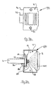
- FIG. 1 shows a perspective view of a connector 2 which is connected to a cable 4.
- the connector 2 may be a generally conventional D-connector having a housing supporting either a male or a female connector block indicated at 8.
- the connector block 8 has pins or sockets to which the wires of the cable 4 are electrically connected.
- the housing may be constructed in any manner, but for ease of manufacture, and to ensure that it shields rf emissions, the connector housing will be made of plastics material which is plated by a metal, such as copper or nickel.
- D-connectors have a housing formed in two parts which are connected to secure the chosen connector block 8 and to define two spaced opposed side walls 10 and two spaced opposed end walls 12.
- the connector block 8 forms a front face of the housing and projects forwardly of the housing and is spaced from a back face 14 in which a cable entry indicated at 16 is formed.
- This cable entry 16 is a generally cylindrical passage extending through the back face of the connector.
- the cable 4 extends through the cable entry 16 into the connector housing.
- the side wall 10 is part of a side wall element 110 also defining half of the rear face 14 and half of the cable entry 16 as can be seen from Figures 3a and 3b.
- the side wall element 110 defines a side wall 10 on whose inner face is provided an upstanding wall 18 defining a recess 20 which extends transversely of and adjacent to the cable entry 16. It will be appreciated that two side wall elements 110 are arranged opposite to one another to define the two side walls 10, the rear face 14 and the cable entry 16.
- each element 110 should be sufficiently high above the inner surface of the side wall 10, at least in parts, that it contacts the corresponding wall 18 of the other element 110 to thereby define a single recess 20 extending between the two side walls 10.
- end parts 19 of each wall 18 may be greater in height than the intermediate part, or a cable shaping indicated at 21 may be provided in the intermediate part for the receipt of the cable 4.
- the position of the connector block 8 and of the cable 4 is indicated in phantom on Figure 3b.
- the cable 4 is preferably a conventional cable having an outer plastics sheath surrounding a number of wires, with a conductive braiding being provided around the wires within the sheath.
- the cable is arranged to extend into the housing through the cable entry 16.
- the plastics material sheath is removed from the end portion of the cable such that the portion of the cable 4 extending across the recess 20 of the side wall 10 is surrounded by the conductive braiding as indicated at 22.
- the braiding is removed to reveal the individual covered wires, the conductive wires of which are connected to the pins or sockets of the connector block 8 in the normal manner.
- a clamp member 30 which is illustrated in Figure 2 is clamped onto the braided part 22 of the cable 4.
- This clamp member is, in the assembled connector, housed within the recess 20 whereby it extends across the opening of the cable entry 16 to prevent rf emissions through the cable entry 16.
- the position of the clamp member 30 in the recess 20 is shown in Figure 3b.
- the clamp member 30 is constructed from two clamping parts.
- a side view of the first clamping part 32 is shown in Figure 2a and a side view of the second clamping part 34 is shown in Figure 2b.
- Figure 2c is an end view of the second clamping part taken in the direction of the arrow C
- Figure 2d is an end view of the first clamping part 32 taken in the direction of the arrow D.
- the first clamping part 32 is a hollow part of substantially rectangular cross-section having two side walls 36 which are arranged spaced from each other and extend substantially parallel.
- the two side walls 36 are joined along their edges by respective outer walls 38.
- a substantially U-shaped cutout 40 is formed in each side wall 36 to open in the front end of the first clamping part 32. This cutout 40 is thereby defined between two spaced, substantially parallel U-shaped channel members 42 whose base is formed by a respective outer wall 38.
- the arms of each U-shaped channel member 42 are defined by the cut away side walls 36.
- a projection 44 is provided to project into each channel member 42.
- the second clamping part 34 comprises a substantially planar member shaped to define two spaced, substantially parallel extending legs 46. These legs 46 define a substantially U-shaped cutout 50 which opens in the front face of the clamping part 34. As is made clear in Figures 2a and 2b, these legs 46 are sized and shaped so that each can be received within a respective channel member 42. As shown, the outer surface of each leg 46 is provided with a series of saw teeth 48 which are directed so that they project towards the rear face of the clamping part 34, that is the face spaced from the front face in which the U-shaped opening 50 opens.
- the legs 46 can be received within, and are movable along, the channels members 42 which act as guide members therefor.
- the two U-shaped openings 40 and 50 together define a closed cable clamping hole, and pushing the two parts 34 and 32 towards one another moves the legs 46 along the channel members 42 and reduces the dimensions of said formed hole.
- additional force has to be exerted onto the two clamping parts so that the saw teeth 48 of the legs 46 are successively pushed over the rib 44. This means that the two parts 32 and 34 cannot easily be pulled apart.
- the two parts 32 and 34 are arranged around a cable and are then moved towards one another such that the cable extends within the cable clamping hole defined thereby.
- the two clamping parts are pushed together so that at least the front saw teeth of the clamping part 34 are engaged over the ribs 44. Further force is exerted on the two clamping parts until the clamp member formed thereby is firmly clamped onto the cable.
- the projections 44 ensure that the clamp remains in clamped engagement on the cable.
- the engaged clamp member 30 is then inserted into the recess 20 defined therefor within the connector housing. It will be appreciated, that in this position there will be no effective hole through the clamp member 30 because it will be tightly clamped on to the cables.
- the clamp member extends across and effectively closes the cable entry 16.
- the clamp member is preferably made of the same material as the connector housing and is a close fit within the recess 20 so that it is in electrical contact not only with the walls of the recess 20, but with the inner surfaces of the side walls 10. In this manner, the housing of the connector forms an electrically connected container for the wires therewithin to shield the uncovered wires.
- the connector shown in Figure 1 has a modular construction having been made from five elements.
- the use of a modular construction enables a variety of specialist connectors to be made very simply and easily.
- Figure 4 shows the basic modular elements which are to be made available to enable a wide variety of different connectors to be provided. In Figure 4 four different modular elements are illustrated.
- the side wall element 110 is the one that is utilised in the connector of Figure 1.
- the side wall elements 110 each comprise a substantially planar, rectangular wall which defines the side wall 10. Along one of its longer edges the side wall 10 is provided with a lip 60 which projects inwardly substantially at right angles to the plane of the side wall 10.
- a wall member 62 is provided along the opposed longer edge of the side wall 10 and extends inwardly, substantially at right angles to the plane of the wall 10, to define part of a front or rear wall of the connector.
- a half cylindrical flange 64 is provided.
- the upstanding wall 18 is provided on the inner surface of the side wall 10 adjacent to the half cylindrical flange 64. It will be appreciated that if two side wall elements 110 are arranged in a connector such that the free edges of their wall members 62 abut, a cable entry 16 will be defined by the two half cylindrical flanges 64, and the two wall members 62 will together define a front or rear wall of the connector, for example as the rear face 14 of the connector shown in Figure 1.
- the alternative side wall element 112 shown in Figure 4 is very similar to the element 110.
- the element 112 includes a substantially planar, rectangular side wall 10 identical in shape and size to that of the side wall element 110.
- the major difference between the two elements 110 and 112 is that the element 112 does not have the wall member 62. Instead, both of its longer edges are provided with an identical lip 60.
- FIG. 4 shows two alternative end wall elements, namely a plane rectangular block element 114 and an alternative end wall element 116.
- Each block 114 or end wall element 116 is provided with a bore 66 arranged to extend the entire longitudinal extent of the block 114. It is also provided with two transversely extending tapped holes 68 which each extend from a longitudinally extending face of the block 114 inwardly. The two tapped holes 68 are aligned at the same longitudinal position of the block 114 and on either side of the bore 66.
- each version of a side wall element 110 and 112 is provided with two holes 70 so that a respective screw, for example as the screw 72 in Figure 1, can be extended through a side wall element 110 or 112 to engage in a respective hole 68 in the side block 114 or 116.
- Connecting screws are also arranged to be extended through the bores 66 of the blocks 114 or elements 116 to connect connector blocks or blanking plates, not illustrated, to the connector housing.
- the end wall element 116 may be used instead of one or both end blocks 114 to define a cable entry into the formed connector housing.
- the end wall element 116 comprises a substantially hollow block having one end face formed with a cylindrical cable entry 76.
- a cable clamp 78 formed of two shaped bands screwed together by way of screws 82 is also provided.
- the side wall and end wall elements illustrated in Figure 4 are used together with connector blocks, and blanking plates and appropriate screws to form a variety of connectors as indicated by Figure 5.
- the connector blocks are substantially conventional D-shaped connector blocks in which a housing containing the pins or sockets is surrounded by a perimetral mounting plate having a screw hole in each end thereof. It will be appreciated that when two side wall elements 110 or 112 are arranged opposed to one another, a connector block can be located such that its perimetral plate engages the inner surface of a respective lip 60 and such that the screw holes in the perimetral plate will each be aligned with a respective bore 66 in a respective end wall element. If a connector block is not required, a substantially planar blanking plate having the same perimetral shape as the perimetral plate of a connector block is provided.
- the connector A shown in Figure 5 is formed from two side wall elements 112 connected by two block elements 114.
- the rear face 84 of the pod connector A will be defined by a blanking plate, whilst a connector block 86 defines its front face.
- the connector B shown in Figure 5 is similar to the pod A except that two connector blocks 86 are provided to form both its rear and front faces. These connector blocks will comprise one female and one male connector block so that the connector B can be used as a "gender changer".
- Connector C in Figure 5 is a "piggyback" connector.It is made from two side wall elements 112, and as with the connector B, two connector blocks 86 form its front and rear surfaces. However, in the connector C one of the end blocks 114 is replaced by an end wall element 116 whereby a cable entry 76 having an associated clamping element 78 is provided.
- the connector D of Figure 5 is similar to that of connector C, but here both end blocks 114 have been replaced by end wall elements 116.
- the connector D therefore has two cable entries 76 and two connector blocks 86 which may be one male and one female, or two male, or two female.
- Connector E of Figure 5 is a basic straight connector and is the connector shown in Figure 1. It will be seen that it has a cable entry 16 and a connector block defining its front face 8. It will be appreciated that this connector E is constructed from two side wall elements 110, two end blocks 114, and a connector block as 86.
- Connector F of Figure 5 is both a straight outlet connector and a right angle outlet connector. It is formed substantially the same as connector E except that one of the end blocks 114 has been omitted and has been replaced by an end wall element 116 including a cable outlet.
- Connector G is a right angle outlet connector formed from two side elements 112, one end block 114, one end wall element 116, one connector block, and a blanking plate.
- the connector H has three cable outlets and one connector block. It is formed from two side wall elements 110 in conjunction with two end wall elements 116 and one connector block.
- the main connectors which will be constructed in factory and offered for sale will be the "gender changer" of Figure 5B, the straight outlet of Figure 5E, and the right angle outlet of Figure 5G. Blanking plates, alternative side wall elements, and alternative end wall elements will also be made available such that the supplied connectors B, E or G can then be adapted as required to make any other specialist connectors needed.
- the elements of Figure 4 could be made of plastics material. However, where rf emissions are to be controlled, the elements are preferably made of metal plated plastics material, for example the plating can be copper or nickel.
- the side wall elements 110 are then provided with appropriate means, as the upstanding wall 18, to receive a clamp member 30 as shown in Figures 2 and 3 to enable the suppression of rf emissions through the cable entries defined by the half cylindrical flanges 64.
- the end blocks 114 for example which are used to connect the side wall elements 110 or 112, are shown as completely rectangular blocks.
- their longitudinally extending faces are chamfered or ridged so that the abutting edge of a respective side wall 10 can seat into the block and there is no possibility of a gap occurring.
- suitable shaping can be provided on the longitudinally extending outer faces of the blocks 116.
Landscapes
- Details Of Connecting Devices For Male And Female Coupling (AREA)
Applications Claiming Priority (2)
| Application Number | Priority Date | Filing Date | Title |
|---|---|---|---|
| GB8929046A GB2242077A (en) | 1989-12-22 | 1989-12-22 | Improvements in electrical connectors |
| GB8929046 | 1989-12-22 |
Publications (1)
| Publication Number | Publication Date |
|---|---|
| EP0434431A1 true EP0434431A1 (de) | 1991-06-26 |
Family
ID=10668410
Family Applications (1)
| Application Number | Title | Priority Date | Filing Date |
|---|---|---|---|
| EP90314032A Withdrawn EP0434431A1 (de) | 1989-12-22 | 1990-12-20 | Verfahren zur Abschirmung eines Kabeleingangs, Einrichtung zur Verbindung an einem Kabel und Klemme |
Country Status (2)
| Country | Link |
|---|---|
| EP (1) | EP0434431A1 (de) |
| GB (1) | GB2242077A (de) |
Cited By (3)
| Publication number | Priority date | Publication date | Assignee | Title |
|---|---|---|---|---|
| WO1993008620A1 (de) * | 1991-10-21 | 1993-04-29 | Siemens Aktiengesellschaft | Abgeschirmter steckverbinder |
| EP2003741A1 (de) * | 2007-06-15 | 2008-12-17 | Souriau | Subminiatur abgeschirmte Verbinderanordnung und Verfahren zum Austatten einer solchen Verbinderandordnug. |
| FR2917542A1 (fr) * | 2007-06-15 | 2008-12-19 | Souriau Soc Par Actions Simpli | Procede pour equiper d'un cable un ensemble de connexion sub-miniature blinde |
Citations (2)
| Publication number | Priority date | Publication date | Assignee | Title |
|---|---|---|---|---|
| US4767345A (en) * | 1987-03-27 | 1988-08-30 | Amp Incorporated | High-density, modular, electrical connector |
| DE8713046U1 (de) * | 1987-09-28 | 1989-01-26 | Siemens AG, 1000 Berlin und 8000 München | Elektrischer Steckverbinder |
Family Cites Families (2)
| Publication number | Priority date | Publication date | Assignee | Title |
|---|---|---|---|---|
| EP0111162A1 (de) * | 1982-11-08 | 1984-06-20 | Microdot Inc. | Gekapselter, abgeschirmter und geerdeter Steckverbinder |
| GB8508557D0 (en) * | 1985-04-02 | 1985-05-09 | Bicc Plc | Electric coupler |
-
1989
- 1989-12-22 GB GB8929046A patent/GB2242077A/en not_active Withdrawn
-
1990
- 1990-12-20 EP EP90314032A patent/EP0434431A1/de not_active Withdrawn
Patent Citations (2)
| Publication number | Priority date | Publication date | Assignee | Title |
|---|---|---|---|---|
| US4767345A (en) * | 1987-03-27 | 1988-08-30 | Amp Incorporated | High-density, modular, electrical connector |
| DE8713046U1 (de) * | 1987-09-28 | 1989-01-26 | Siemens AG, 1000 Berlin und 8000 München | Elektrischer Steckverbinder |
Cited By (4)
| Publication number | Priority date | Publication date | Assignee | Title |
|---|---|---|---|---|
| WO1993008620A1 (de) * | 1991-10-21 | 1993-04-29 | Siemens Aktiengesellschaft | Abgeschirmter steckverbinder |
| EP2003741A1 (de) * | 2007-06-15 | 2008-12-17 | Souriau | Subminiatur abgeschirmte Verbinderanordnung und Verfahren zum Austatten einer solchen Verbinderandordnug. |
| FR2917542A1 (fr) * | 2007-06-15 | 2008-12-19 | Souriau Soc Par Actions Simpli | Procede pour equiper d'un cable un ensemble de connexion sub-miniature blinde |
| US7670180B2 (en) | 2007-06-15 | 2010-03-02 | Souriau | Shielded subminiature connection assembly and process of forming such an assembly |
Also Published As
| Publication number | Publication date |
|---|---|
| GB2242077A (en) | 1991-09-18 |
| GB8929046D0 (en) | 1990-02-28 |
Similar Documents
| Publication | Publication Date | Title |
|---|---|---|
| US5647765A (en) | Shielded connector with conductive gasket interface | |
| DE69411855T2 (de) | Elektrischer Verbinder mit Zugentlastung | |
| EP0118168B2 (de) | Elektrischer Steckverbinder und Steckdose dafür | |
| DE3650030T2 (de) | Abgeschirmte Steckerbuchse-Steckverbindung. | |
| EP0040941A1 (de) | Abschirmung für eine elektrische Steckverbindung | |
| US4838811A (en) | Modular connector with EMI countermeasure | |
| DE69018356T2 (de) | Modularer Steckverbinder. | |
| US4456321A (en) | Two-piece, push-on type grounding clip | |
| US5562493A (en) | Network interface assembly and mounting frame | |
| US8777665B2 (en) | Shielded connector | |
| DE69324536T2 (de) | Hochfrequenzkabelverbinder | |
| DE69413342T2 (de) | Abgeschirmter Steckverbinder mit Zwittergehäuseschalen | |
| EP0490078B1 (de) | Abgeschirmter elektrischer Verbinder | |
| EP0390450A1 (de) | Stapelbarer Zwillingsverbinder für Schnittstellenbus | |
| DE69412037T2 (de) | Elektrischer Verbinder mit Erdklemme für Kabelabschirmung | |
| EP0873581B1 (de) | Elektrische steckvorrichtung | |
| EP1989764A1 (de) | Stecker für geschirmte datenkabel | |
| US4715827A (en) | Modular connector system | |
| EP0475414A1 (de) | Elektrischer Verbinder | |
| GB2042827A (en) | Connector hood constructions | |
| EP0597473A2 (de) | Elektrische Verbinderanordnung | |
| DE69402889T2 (de) | Vertikal ausgerichtete elektrische Verbinderbauteile | |
| DE69110382T2 (de) | Elektrischer Verbinder. | |
| DE69415645T2 (de) | Elektrischer Verbinder mit Leiterhalterung | |
| DE69405060T2 (de) | Drahtverbindevorrichtung und Anschlussklemme dazu |
Legal Events
| Date | Code | Title | Description |
|---|---|---|---|
| PUAI | Public reference made under article 153(3) epc to a published international application that has entered the european phase |
Free format text: ORIGINAL CODE: 0009012 |
|
| AK | Designated contracting states |
Kind code of ref document: A1 Designated state(s): DE ES FR IT SE |
|
| 17P | Request for examination filed |
Effective date: 19911205 |
|
| 17Q | First examination report despatched |
Effective date: 19940610 |
|
| STAA | Information on the status of an ep patent application or granted ep patent |
Free format text: STATUS: THE APPLICATION IS DEEMED TO BE WITHDRAWN |
|
| 18D | Application deemed to be withdrawn |
Effective date: 19941021 |