EP0434607A1 - Kolbenkompressor der Horizontalbauart - Google Patents
Kolbenkompressor der Horizontalbauart Download PDFInfo
- Publication number
- EP0434607A1 EP0434607A1 EP90810900A EP90810900A EP0434607A1 EP 0434607 A1 EP0434607 A1 EP 0434607A1 EP 90810900 A EP90810900 A EP 90810900A EP 90810900 A EP90810900 A EP 90810900A EP 0434607 A1 EP0434607 A1 EP 0434607A1
- Authority
- EP
- European Patent Office
- Prior art keywords
- piston
- piston rod
- bore
- axis
- crosshead
- Prior art date
- Legal status (The legal status is an assumption and is not a legal conclusion. Google has not performed a legal analysis and makes no representation as to the accuracy of the status listed.)
- Granted
Links
- 230000006835 compression Effects 0.000 description 1
- 238000007906 compression Methods 0.000 description 1
- 238000010276 construction Methods 0.000 description 1
- 210000004907 gland Anatomy 0.000 description 1
- 238000005259 measurement Methods 0.000 description 1
- 230000002093 peripheral effect Effects 0.000 description 1
- 238000007789 sealing Methods 0.000 description 1
Images

Classifications
-
- F—MECHANICAL ENGINEERING; LIGHTING; HEATING; WEAPONS; BLASTING
- F16—ENGINEERING ELEMENTS AND UNITS; GENERAL MEASURES FOR PRODUCING AND MAINTAINING EFFECTIVE FUNCTIONING OF MACHINES OR INSTALLATIONS; THERMAL INSULATION IN GENERAL
- F16J—PISTONS; CYLINDERS; SEALINGS
- F16J1/00—Pistons; Trunk pistons; Plungers
- F16J1/10—Connection to driving members
- F16J1/12—Connection to driving members with piston-rods, e.g. rigid connections
-
- F—MECHANICAL ENGINEERING; LIGHTING; HEATING; WEAPONS; BLASTING
- F04—POSITIVE - DISPLACEMENT MACHINES FOR LIQUIDS; PUMPS FOR LIQUIDS OR ELASTIC FLUIDS
- F04B—POSITIVE-DISPLACEMENT MACHINES FOR LIQUIDS; PUMPS
- F04B39/00—Component parts, details, or accessories, of pumps or pumping systems specially adapted for elastic fluids, not otherwise provided for in, or of interest apart from, groups F04B25/00 - F04B37/00
- F04B39/0005—Component parts, details, or accessories, of pumps or pumping systems specially adapted for elastic fluids, not otherwise provided for in, or of interest apart from, groups F04B25/00 - F04B37/00 adaptations of pistons
- F04B39/0022—Component parts, details, or accessories, of pumps or pumping systems specially adapted for elastic fluids, not otherwise provided for in, or of interest apart from, groups F04B25/00 - F04B37/00 adaptations of pistons piston rods
Definitions
- the invention relates to a piston compressor having at least one cylinder having a substantially horizontal axis and a piston guided therein, which is driven by a crankshaft via a piston rod and a crosshead, the end of the piston rod facing away from the crosshead protruding into a bore in the piston and the piston is detachably connected to this piston rod end.
- the invention has for its object to improve a piston compressor of the type mentioned in such a way that an adjustment of the crosshead axis is avoided and the "runout" of the piston rod can be minimized.
- the bore on the end face of the piston facing the crosshead has an enlarged bore section which is arranged eccentrically to the outside diameter of the piston and that an eccentric ring is arranged between this bore section and the piston rod projecting into it, the inner bore diameter of which is equal to the diameter is the piston rod and the outside diameter of which is eccentric to the inner bore is equal to the diameter of the enlarged bore section.
- the eccentricity of the enlarged section of the piston bore and the attachment of the eccentric ring make it possible to adjust the axis of the piston relative to the axis of the piston rod so that the axis of the piston rod remains in alignment with the axis of the crosshead and the cylinder axis.
- This setting can be made both when the compressor is first installed and after certain operating times, ie if wear has occurred on the piston or possibly on the piston guide rings due to the operation and the tolerated "runout" value has been exceeded.
- the attachment of the eccentric ring is structurally simpler than the axis of the crosshead training to be adjustable. Handling the eccentric ring for adjusting the piston is also easier than adjusting the axis of the crosshead.
- the piston compressor has a crankcase 1 in which a crankshaft 2 is mounted. At a crank pin 3 of the crankshaft 2 is connected to a push rod 4, which is articulated at its left end in FIG. 1 to a pin 5, which is part of a horizontally straight reciprocating crosshead 6.
- a piston rod 7 is attached to the crosshead 6, which penetrates the crankcase 1 in the region of an oil scraper device 8 and which is detachably connected to a piston 9 at its left end in FIG. 1.
- the piston 9 is provided in a manner known per se with piston and guide rings, not shown, for example made of plastic. It is guided in a cylinder 10 connected to the crankcase 1 and is moved horizontally back and forth by the piston rod 7.
- the piston 9 is provided with a through bore 13, the axis 13 'eccentric to the piston axis 9', that is to the axis of rotation of the peripheral or outer surface of the piston 9.
- the bore 13 is expanded at its left end in Fig. 2 to a bore 14, the axis 14 'is aligned with the axis 13'.
- a shoulder 15 is present between the bores 13 and 14.
- the right end of the bore 13 in FIG. 2 is expanded to a bore 16, the axis 16 'is aligned with the axis 13' and passes over a shoulder 17 in the bore 13.
- an eccentric ring 18 is arranged, the outside diameter of which - apart from the necessary tolerances - is equal to the diameter of the bore 16.
- the inner bore 19 of the eccentric ring 18 is eccentric to its outer diameter and - apart from the necessary tolerances - is the same as the diameter of the piston rod 7, of which one end section is enclosed by the inner bore 19.
- the axis of the inner bore 19 is aligned with the axis 7 'of the piston rod.
- the inner bore 19 merges at its left end in FIG. 2 into a shoulder 20, against which the piston rod 7 rests with an end face 21 in the assembled state.
- a rod extension 22 extends from the end face 21 of the piston rod 7 to the left in FIG. 2, which extends through the bore 13 of the piston 9 and is provided with a thread at its end projecting into the enlarged bore 14.
- a nut 23 is screwed onto this thread, which lies against the shoulder 15 and ensures the connection between the piston rod 7 and the piston 9.
- the eccentric ring 18 has on its outer end face two diametrically arranged blind bores 25, which serve to receive a suitable tool, with the aid of which the eccentric ring can be adjusted.
- the eccentric ring 18 is provided on its outer end face with a scale 26 which ranges from 0 to 10 and extends over half the circumference of the eccentric ring.
- a mark 27 is attached in its end face.
- a scale 28 is also attached to the end of the piston 9 facing away from the crosshead, which extends over a quarter of the piston circumference and, according to the scale 26, comprises the scale values from 0 to 10.
- the piston 9 is adjusted relative to the piston rod 7 in the following manner. If the eccentric ring 18 with its scale value 0 faces the mark 27, then the piston rod 7 is exactly centered on the piston 9, ie the axes 7 'and 9' coincide. Since in practice the course of the piston rod axis 7 'deviates from the ideal course of a horizontal axis, the two axes are adjusted relative to one another in such a way that the piston rod axis at least approximates the ideal position of the horizontal axis. Based on measurements on the piston rod, the size of the deviation of the piston rod axis from the horizontal axis can be determined and the size of the scale value for rotating the eccentric ring 18 can be determined therefrom. In the example according to FIGS. 3 and 4, this scale value is 5.
- the eccentricity of the piston bore 13, 14, 16 and the eccentricity of the eccentric ring 18 are the same. Deviating from this, these eccentricities can also be of different sizes.
- the bores 13 and 14 may be concentric with the outer diameter of the piston 9, the clearance between the rod extension 22 and the bore 13 and the clearance between the nut 23 and the bore 14 being dimensioned accordingly. It is also possible to arrange the scale division 28 on the piston 9 on the end face of the piston facing the crosshead. Instead of the blind bores 25, differently designed engagement surfaces for the adjusting tool on the eccentric ring 18 can also be provided.
Landscapes
- Engineering & Computer Science (AREA)
- General Engineering & Computer Science (AREA)
- Mechanical Engineering (AREA)
- Chemical & Material Sciences (AREA)
- Combustion & Propulsion (AREA)
- Compressor (AREA)
- Compressors, Vaccum Pumps And Other Relevant Systems (AREA)
- Applications Or Details Of Rotary Compressors (AREA)
Abstract
Description
- Die Erfindung bezieht sich auf einen Kolbenkompressor mit mindestens einem eine im wesentlichen horizontale Achse aufweisenden Zylinder und einem darin geführten Kolben, der über eine Kolbenstange und einen Kreuzkopf von einer Kurbelwelle angetrieben ist, wobei das dem Kreuzkopf abgewendete Ende der Kolbenstange in eine Bohrung des Kolbens ragt und der Kolben mit diesem Kolbenstangenende lösbar verbunden ist.
- Bei Kolbenkompressoren dieser Art besteht das Problem, dass sich die am Kreuzkopf befestigte Kolbenstange mit ihrem den Kolben tragenden Ende nach unten ausbiegt und ihre Achse damit von dem idealen horizontalen Verlauf abweicht. Diese Abweichung wird im Laufe des Betriebes des Kolbenkompressors zusätzlich grösser infolge der Abnützung des Kolbens oder der Abnützung von Kolbenführungsringen, falls der Kolben mit solchen Ringen versehen ist. Diese Abweichung wird in Fachkreisen auch mit "runout" bezeichnet, und für die Grösse dieses "runout" sind in den Konstruktionsrichtlinien der amerikanischen Erdölindustrie bestimmte Toleranzwerte vorgeschrieben. Um zu gross gewordene "runout"-Werte auszugleichen, ist es schon bekannt, die Achse des Kreuzkopfes und damit der Kolbenstangenbefestigung zu verstellen. Diese Massnahme hat jedoch den Nachteil, dass der Kreuzkopf und die Kolbenstange relativ zum Zylinder und zum Stopfbuchsenlager, das die Kolbenstange beim Durchtritt durch die Zylinderstirnwand umschliesst, aus der Flucht verstellt werden. Dies hat ein einseitiges Spiel zwischen der Kolbenstange und dem Stopfbuchsenlager zur Folge, wodurch die Dichtungsringe dieses Lagers exzentrisch gestützt werden, was zu verringerter Standzeit führen kann.
- Der Erfindung liegt die Aufgabe zugrunde, einen Kolbenkompressor der eingangs genannten Art dahingehend zu verbessern, dass ein Verstellen der Kreuzkopfachse vermieden wird und trotzdem der "runout" der Kolbenstange minimiert werden kann.
- Diese Aufgabe wird erfindungsgemäss dadurch gelöst, dass die Bohrung auf der dem Kreuzkopf zugewendeten Stirnseite des Kolbens einen erweiterten, zum Aussendurchmesser des Kolbens exzentrisch angeordneten Bohrungsabschnitt aufweist und dass zwischen diesem Bohrungsabschnitt und der in ihn ragenden Kolbenstange ein Exzenterring angeordnet ist, dessen Innenbohrungsdurchmesser gleich dem Durchmesser der Kolbenstange ist und dessen zur Innenbohrung exzentrischer Aussendurchmesser gleich dem Durchmesser des erweiterten Bohrungsabschnittes ist. Durch die Exzentrizität des erweiterten Abschnitts der Kolbenbohrung und das Anbringen des Exzenterringes wird es möglich, die Achse des Kolbens relativ zur Achse der Kolbenstange so einzustellen, dass die Achse der Kolbenstange mit der Achse des Kreuzkopfes und der Zylinderachse in der Flucht bleibt. Dieses Einstellen kann sowohl bei der Erstmontage des Kompressors als auch nach gewissen Betriebszeiten erfolgen, d.h. wenn wegen des Betriebes Abnützungen am Kolben oder gegebenenfalls an den Kolbenführungsringen aufgetreten sind und der tolerierte "runout"-Wert überschritten worden ist. Darüberhinaus ist von Vorteil, dass das Anbringen des Exzenterringes konstruktiv einfacher ist, als die Achse des Kreuzkopfes nachstellbar auszubilden. Auch die Handhabung des Exzenterringes zwecks Einstellens des Kolbens ist einfacher als das Verstellen der Achse des Kreuzkopfes.
- Ein Ausführungsbeispiel der Erfindung ist in der folgenden Beschreibung anhand der Zeichnung näher erläutert. Es zeigen:
- Fig. 1 einen schematisch stark vereinfachten Vertikalschnitt durch einen Kolbenkompressor der Horizontalbauart,
- Fig. 2 einen Schnitt durch den Kolben mit dem in ihn hineinragenden Kolbenstangenende,
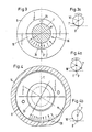
- Fig. 3 eine Ansicht des Kolbens in Richtung des Pfeiles A in Fig. 2 in einem Zwischenzustand der Montage,
- Fig. 3a ein Detail aus Fig. 3 in vergrössertem Massstab,
- Fig. 4 eine Ansicht des Kolbens in Richtung des Pfeiles B in Fig. 2 im Endzustand der Montage,
- Fig. 4a ein Detail aus Fig. 4 in vergrössertem Massstab, jedoch im Zwischenzustand gemäss Fig. 3a und
- Fig. 4b das gleiche Detail wie Fig. 4a, jedoch im Endzustand.
- Gemäss Fig. 1 weist der Kolbenkompressor ein Kurbelgehäuse 1 auf, in dem eine Kurbelwelle 2 gelagert ist. An einem Kurbelzapfen 3 der Kurbelwelle 2 ist eine Schubstange 4 angeschlossen, die an ihrem in Fig. 1 linken Ende mit einem Zapfen 5 gelenkig verbunden ist, der Teil eines horizontal geradlinig hin und her beweglichen Kreuzkopfes 6 ist. An dem Kreuzkopf 6 ist eine Kolbenstange 7 befestigt, die das Kurbelgehäuse 1 im Bereich einer Oelabstreifvorrichtung 8 durchdringt und die an ihrem in Fig. 1 linken Ende mit einem Kolben 9 lösbar verbunden ist. Der Kolben 9 ist in an sich bekannter Weise mit nicht dargestellten Kolben- und Führungsringen z.B. aus Kunststoff versehen. Er ist in einem mit dem Kurbelgehäuse 1 verbundenen Zylinder 10 geführt und wird von der Kolbenstange 7 horizontal hin und her bewegt. Bei einer Bewegung des Kolbens 9 in Richtung zum Kurbelgehäuse 1 wird im Zylinderraum 40 zu Komprimierendes Gas angesaugt, das dann bei der Bewegung in der entgegengesetzten Richtung komprimiert wird. Nahe der Stelle, an der der Kolben 9 vom Saughub zum Kompressionshub umkehrt, ist zwischen dem Kolben und der Oelabstreifvorrichtung 8 im Zylinder 10 eine Stirnwand 11 vorgesehen, die im Durchtrittsbereich der Kolbenstange 7 mit einer diese umschliessenden Stopfbüchsdichtung 12 versehen ist. In Fig. 1 sind die Achse der Kolbenstange 7 mit 7′, die Achse des Kolbens 9 mit 9′ und die Achse des Zylinders 10 mit 10′ bezeichnet. Abweichend von der Praxis sind sie hier miteinander fluchtend dargestellt.
- Gemäss Fig. 2 ist der Kolben 9 mit einer durchgehenden Bohrung 13 versehen, deren Achse 13′ exzentrisch zur Kolbenachse 9′, d.h. zur Rotationsachse der Umfangs- oder Aussenfläche des Kolbens 9 liegt. Die Bohrung 13 ist an ihrem in Fig. 2 linken Ende zu einer Bohrung 14 erweitert, deren Achse 14′ mit der Achse 13′ fluchtet. Zwischen den Bohrungen 13 und 14 ist eine Schulter 15 vorhanden. Auch das in Fig. 2 rechte Ende der Bohrung 13 ist zu einer Bohrung 16 erweitert, deren Achse 16′ mit der Achse 13′ fluchtet und die über eine Schulter 17 in die Bohrung 13 übergeht.
- In der erweiterten, ebenfalls zum Aussendurchmesser des Kolbens 9 exzentrischen Bohrung 16 ist ein Exzenterring 18 angeordnet, dessen Aussendurchmesser ― abgesehen von den notwendigen Toleranzen ― gleich dem Durchmesser der Bohrung 16 ist. In der gezeichneten Lage des Exzenterringes 18 fluchtet die Achse seines Aussendurchmessers mit der Achse 16′. Die Innenbohrung 19 des Exzenterringes 18 liegt exzentrisch zu dessen Aussendurchmesser und ist ― abgesehen von den notwendigen Toleranzen ― gleich dem Durchmesser der Kolbenstange 7, von der ein Endabschnitt von der Innenbohrung 19 umschlossen ist. Die Achse der Innenbohrung 19 fluchtet mit der Achse 7′ der Kolbenstange. Die Innenbohrung 19 geht an ihrem in Fig. 2 linken Ende in eine Schulter 20 über, an der im montierten Zustand die Kolbenstange 7 mit einer Stirnfläche 21 anliegt.
- Von der Stirnfläche 21 der Kolbenstange 7 geht in Fig. 2 nach links ein Stangenfortsatz 22 aus, der sich durch die Bohrung 13 des Kolbens 9 erstreckt und an seinem in die erweiterte Bohrung 14 ragenden Ende mit einem Gewinde versehen ist. Auf dieses Gewinde ist eine Mutter 23 geschraubt, die sich an die Schulter 15 anlegt und die Verbindung zwischen Kolbenstange 7 und Kolben 9 sicherstellt. Der Exzenterring 18 weist auf seiner äusseren Stirnfläche zwei zueinander diametral angeordnete Sackbohrungen 25 auf, die zum Aufnehmen eines passenden Werkzeugs dienen, mit dessen Hilfe der Exzenterring verstellt werden kann.
- Gemäss Fig. 3 ist der Exzenterring 18 auf seiner äusseren Stirnfläche mit einer Skala 26 versehen, die von 0 bis 10 reicht und sich über den halben Umfang des Exzenterringes erstreckt. An der tiefsten Stelle der erweiterten Bohrung 16 des Kolbens 9 ist in dessen Stirnfläche eine Marke 27 angebracht. Wie sich aus Fig. 3a ergibt, befindet sich bei dem in Fig. 3 gezeichneten Montagebeispiel die Achse 7′ der Kolbenstange links oberhalb der Achse 9′ des Kolbens 9, wogegen rechts von der Achse 7′ sowie oberhalb der Achse 9′ die Achse 16′ liegt, die identisch mit der Lage der Achse des Aussendurchmessers des Exzenterringes 18 ist.
- Gemäss Fig. 4 ist auch auf der dem Kreuzkopf abgewendeten Stirnseite des Kolbens 9 eine Skala 28 angebracht, die sich über einen Viertel des Kolbenumfangs erstreckt und entsprechend der Skala 26 die Skalenwerte von 0 bis 10 umfasst.
- Das Einstellen des Kolbens 9 relativ zur Kolbenstange 7 geschieht in folgender Weise. Wenn der Exzenterring 18 mit seinem Skalenwert 0 der Marke 27 gegenübersteht, so liegt die Kolbenstange 7 genau zentrisch zum Kolben 9, d.h. die Achsen 7′ und 9′ fallen zusammen. Da in der Praxis der Verlauf der Kolbenstangenachse 7′ von dem idealen Verlauf einer horizontalen Achse abweicht, werden die beiden Achsen so zueinander verstellt, dass die Kolbenstangenachse zumindest der idealen Lage der Horizontalachse nahekommt. Aufgrund von Messungen an der Kolbenstange kann die Grösse der Abweichung der Kolbenstangenachse von der horizontalen Achse festgestellt und daraus die Grösse des Skalenwertes für das Verdrehen des Exzenterringes 18 bestimmt werden. Im Beispiel nach Fig. 3 und 4 beträgt dieser Skalenwert 5. Vor dem Anziehen der Kolbenmutter 23 wird also der Exzenterring 18 soweit im Uhrzeigersinn in Fig. 3 gedreht, dass der Skalenwert 5 mit der Marke 27 bündig steht. Hierdurch wird also die Kolbenstangenachse 7′ relativ zur Kolbenachse 9′ angehoben (Fig. 3a und 4a). Nunmehr wird die Mutter 23 angezogen, so dass sich die relative Stellung des Kolbens 9 zur Kolbenstange 7 nicht mehr ändert. Als nächstes wird der Kolben zusammen mit der in ihm fixierten Kolbenstange relativ zum Zylinder 10 aus der in Fig. 4a gezeigten Stellung im Gegenuhrzeigersinn in die in Fig. 4b gezeigte Stellung gedreht, um zu erreichen, dass die Kolbenstangenachse 7′ und die Kolbenachse 9′ in derselben vertikalen Ebene E liegen wie die Achse 10′ des Zylinders 10. Dies wird mit Hilfe der Skala 2B bewirkt, indem deren Skalenwert 5 bündig zur vertikalen Ebene E eingestellt wird, in der sich die Zylinderachse 10′ befindet, wie dies in Fig. 4 und 4b dargestellt ist. Nunmehr wird die feste Verbindung zwischen der Kolbenstange 7 und dem Kreuzkopf 6 hergestellt.
- In dem beschriebenen Ausführungsbeispiel sind die Exzentrizität der Kolbenbohrung 13, 14, 16 und die Exzentrizität des Exzenterringes 18 gleich gross. Abweichend davon können diese Exzentrizitäten auch verschieden gross sein. Ausserdem können die Bohrungen 13 und 14 konzentrisch zum Aussendurchmesser des Kolbens 9 liegen, wobei das Spiel zwischen dem Stangenfortsatz 22 und der Bohrung 13 sowie das Spiel zwischen der Mutter 23 und der Bohrung 14 entsprechend gross zu bemessen sind. Auch ist es möglich, die Skaleneinteilung 28 am Kolben 9 auf der dem Kreuzkopf zugewendeten Stirnfläche des Kolbens anzubringen. Anstelle der Sackbohrungen 25 können auch anders gestaltete Angriffsflächen für das Verstellwerkzeug am Exzenterring 18 vorgesehen werden.
Claims (4)
- Kolbenkompressor mit mindestens einem eine im wesentlichen horizontale Achse aufweisenden Zylinder und einem darin geführten Kolben, der über eine Kolbenstange und einen Kreuzkopf von einer Kurbelwelle angetrieben ist, wobei das dem Kreuzkopf abgewendete Ende der Kolbenstange in eine Bohrung des Kolbens ragt und der Kolben mit diesem Kolbenstangenende lösbar verbunden ist, dadurch gekennzeichnet, dass die Bohrung (13) auf der dem Kreuzkopf (6) zugewendeten Stirnseite des Kolbens (9) einen erweiterten, zum Aussendurchmesser des Kolbens exzentrisch angeordneten Bohrungsabschnitt (16) aufweist und dass zwischen diesem Bohrungsabschnitt (16) und der in ihn ragenden Kolbenstange (7) ein Exzenterring (18) angeordnet ist, dessen Innenbohrungsdurchmesser gleich dem Durchmesser der Kolbenstange (7) ist und dessen zur Innenbohrung (19) exzentrischer Aussendurchmesser gleich dem Durchmesser des erweiterten Bohrungsabschnittes (16) ist.
- Kolbenkompressor nach Anspruch 1, dadurch gekennzeichnet, dass der Exzenterring (18) auf seiner dem Kreuzkopf (6) zugewendeten Stirnfläche und die dem Kreuzkopf (6) abgewendete Stirnfläche des Kolbens (9) mit je einer Skaleneinteilung (26 bzw. 28) versehen sind.
- Kolbenkompressor nach Anspruch 1 oder 2, dadurch gekennzeichnet, dass der Kolben (9) auf der dem Kreuzkopf (6) abgewendeten Stirnseite einen erweiterten Bohrungsabschnitt (14) aufweist, in dem eine die Kolbenstange (7) mit dem Kolben (9) verbindende Mutter (23) angeordnet ist.
- Kolbenkompressor nach Anspruch 3, dadurch gekennzeichnet, dass auch der Bohrungsabschnitt (14) des Kolbens (9) exzentrisch zum Aussendurchmesser des Kolbens angeordnet ist und die Exzentrizität dieses Bohrungsabschnittes (14) und die Exzentrizität des Exzenterringes (18) gleiche Grösse aufweisen.
Priority Applications (1)
| Application Number | Priority Date | Filing Date | Title |
|---|---|---|---|
| AT90810900T ATE104018T1 (de) | 1989-12-21 | 1990-11-21 | Kolbenkompressor der horizontalbauart. |
Applications Claiming Priority (2)
| Application Number | Priority Date | Filing Date | Title |
|---|---|---|---|
| CH457389 | 1989-12-21 | ||
| CH4573/89 | 1989-12-21 |
Publications (2)
| Publication Number | Publication Date |
|---|---|
| EP0434607A1 true EP0434607A1 (de) | 1991-06-26 |
| EP0434607B1 EP0434607B1 (de) | 1994-04-06 |
Family
ID=4278611
Family Applications (1)
| Application Number | Title | Priority Date | Filing Date |
|---|---|---|---|
| EP90810900A Expired - Lifetime EP0434607B1 (de) | 1989-12-21 | 1990-11-21 | Kolbenkompressor der Horizontalbauart |
Country Status (4)
| Country | Link |
|---|---|
| EP (1) | EP0434607B1 (de) |
| JP (1) | JP2788790B2 (de) |
| AT (1) | ATE104018T1 (de) |
| DE (1) | DE59005268D1 (de) |
Cited By (3)
| Publication number | Priority date | Publication date | Assignee | Title |
|---|---|---|---|---|
| US6016738A (en) * | 1994-11-10 | 2000-01-25 | Thomassen International B.V. | Piston compressor of the horizontal type |
| DE10048701C1 (de) * | 2000-09-30 | 2002-06-13 | Neuman & Esser Maschf | Kolbenkompressor und Verfahren zur Kolbenstangenjustierung |
| EP1659302A1 (de) * | 2004-11-17 | 2006-05-24 | Nuovo Pignone Holding S.P.A. | Verbindung zwischen Kolbenstange und Querspritzkopf einer hin- und hergehenden Maschine |
Citations (4)
| Publication number | Priority date | Publication date | Assignee | Title |
|---|---|---|---|---|
| FR709490A (fr) * | 1930-04-19 | 1931-08-07 | Maschb Ag Vormals Ehrhardt & S | Accouplement de tiges de piston pour compresseurs à pressions très élevées |
| US1835662A (en) * | 1931-02-12 | 1931-12-08 | Ingersoll Rand Co | Floating plunger |
| US3036873A (en) * | 1961-09-13 | 1962-05-29 | Kimwood Machine Co | Piston and piston rod connection |
| DE2061063A1 (de) * | 1969-12-15 | 1971-06-24 | Dart Ind Inc | Vorrichtung zur federnden Verbindung eines Bauteils mit einem Antrieb |
-
1990
- 1990-11-21 DE DE90810900T patent/DE59005268D1/de not_active Expired - Fee Related
- 1990-11-21 EP EP90810900A patent/EP0434607B1/de not_active Expired - Lifetime
- 1990-11-21 AT AT90810900T patent/ATE104018T1/de not_active IP Right Cessation
- 1990-12-20 JP JP2404119A patent/JP2788790B2/ja not_active Expired - Lifetime
Patent Citations (4)
| Publication number | Priority date | Publication date | Assignee | Title |
|---|---|---|---|---|
| FR709490A (fr) * | 1930-04-19 | 1931-08-07 | Maschb Ag Vormals Ehrhardt & S | Accouplement de tiges de piston pour compresseurs à pressions très élevées |
| US1835662A (en) * | 1931-02-12 | 1931-12-08 | Ingersoll Rand Co | Floating plunger |
| US3036873A (en) * | 1961-09-13 | 1962-05-29 | Kimwood Machine Co | Piston and piston rod connection |
| DE2061063A1 (de) * | 1969-12-15 | 1971-06-24 | Dart Ind Inc | Vorrichtung zur federnden Verbindung eines Bauteils mit einem Antrieb |
Cited By (5)
| Publication number | Priority date | Publication date | Assignee | Title |
|---|---|---|---|---|
| US6016738A (en) * | 1994-11-10 | 2000-01-25 | Thomassen International B.V. | Piston compressor of the horizontal type |
| RU2154190C2 (ru) * | 1994-11-10 | 2000-08-10 | Томассен Компрешн Системз Б.В. | Поршневой компрессор горизонтального типа |
| CZ296775B6 (cs) * | 1994-11-10 | 2006-06-14 | Thomassen Compression Systems B.V. | Pístový kompresor pro stlacování plynu a píst v kombinaci s pístovým kompresorem |
| DE10048701C1 (de) * | 2000-09-30 | 2002-06-13 | Neuman & Esser Maschf | Kolbenkompressor und Verfahren zur Kolbenstangenjustierung |
| EP1659302A1 (de) * | 2004-11-17 | 2006-05-24 | Nuovo Pignone Holding S.P.A. | Verbindung zwischen Kolbenstange und Querspritzkopf einer hin- und hergehenden Maschine |
Also Published As
| Publication number | Publication date |
|---|---|
| DE59005268D1 (de) | 1994-05-11 |
| JP2788790B2 (ja) | 1998-08-20 |
| JPH06213158A (ja) | 1994-08-02 |
| ATE104018T1 (de) | 1994-04-15 |
| EP0434607B1 (de) | 1994-04-06 |
Similar Documents
| Publication | Publication Date | Title |
|---|---|---|
| DE2104191C3 (de) | Vorrichtung zur Förderung von breiigen, abbindenden Massen | |
| DE19503621A1 (de) | Hubkolbenpumpe | |
| EP0006863A1 (de) | Apparat zum homogenisieren von flüssigen und breiigen substanzen | |
| EP0640764B1 (de) | Kolbenkompressor | |
| AT8401U1 (de) | Kältemittelverdichter | |
| EP0434607B1 (de) | Kolbenkompressor der Horizontalbauart | |
| DE3517123C2 (de) | Handhebel-Fettpresse | |
| DE602005005136T2 (de) | Verbindung zwischen Kolbenstange und Querspritzkopf einer hin- und hergehenden Maschine | |
| DE19512162C1 (de) | Kolben für ein Dosiergerät, Titriergerät oder dergleichen | |
| EP0866933A1 (de) | Kolben-zylinder-baueinheit | |
| DE19808251A1 (de) | Kompressor, insbesondere für eine Klimaanlage eines Kraftfahrzeugs | |
| EP0398078A2 (de) | Kompakter Kolbenvibrator | |
| DE10122512C2 (de) | Hydraulikzylinder mit Schwenkzapfen | |
| DE102010006958B4 (de) | Verfahren zur Montage eines Kolbens und eines Pleuels in einem Zylinder einer Brennkraftmaschine sowie Brennkraftmaschine | |
| DE3204785C2 (de) | Lufthammer | |
| DE10048701C1 (de) | Kolbenkompressor und Verfahren zur Kolbenstangenjustierung | |
| DE3602576A1 (de) | Tauchkolben, insbesondere fuer verbrennungsmotoren, mit fest an den kolbenbolzen montiertem pleuel | |
| DE3641783A1 (de) | Zug- und druckkraefte uebertragende gelenkverbindung zwischen einem kolben und einem pleuel | |
| EP0262167A1 (de) | Kraftstoffeinspritzpumpe für brennkraftmaschinen. | |
| DE102005040496A1 (de) | Verfahren zur Montage eines Kurbeltriebs und Kolbenverdichter | |
| DE3143306C2 (de) | Kolbenbrennkraftmaschine mit einer Kolbenring- und Zylinderlaufflächenanordnung | |
| DE10037659C2 (de) | Hubkolbenmaschine | |
| DE19515950C2 (de) | Gleitdichtung in einem pneumatischen Mehrstellungsventil | |
| DE1204072B (de) | Vorrichtung zum Austragen und gleichzeitigen Foerdern zementhaltiger Massen aus einem Vorratsbehaelter mit einer nach unten foerdernden einwelligen Schneckenpumpe | |
| DE2652346C3 (de) |
Legal Events
| Date | Code | Title | Description |
|---|---|---|---|
| PUAI | Public reference made under article 153(3) epc to a published international application that has entered the european phase |
Free format text: ORIGINAL CODE: 0009012 |
|
| 17P | Request for examination filed |
Effective date: 19901126 |
|
| AK | Designated contracting states |
Kind code of ref document: A1 Designated state(s): AT CH DE FR GB IT LI NL |
|
| 17Q | First examination report despatched |
Effective date: 19930830 |
|
| GRAA | (expected) grant |
Free format text: ORIGINAL CODE: 0009210 |
|
| AK | Designated contracting states |
Kind code of ref document: B1 Designated state(s): AT CH DE FR GB IT LI NL |
|
| REF | Corresponds to: |
Ref document number: 104018 Country of ref document: AT Date of ref document: 19940415 Kind code of ref document: T |
|
| REF | Corresponds to: |
Ref document number: 59005268 Country of ref document: DE Date of ref document: 19940511 |
|
| GBT | Gb: translation of ep patent filed (gb section 77(6)(a)/1977) |
Effective date: 19940414 |
|
| ITF | It: translation for a ep patent filed | ||
| ET | Fr: translation filed | ||
| PLBE | No opposition filed within time limit |
Free format text: ORIGINAL CODE: 0009261 |
|
| STAA | Information on the status of an ep patent application or granted ep patent |
Free format text: STATUS: NO OPPOSITION FILED WITHIN TIME LIMIT |
|
| 26N | No opposition filed | ||
| PGFP | Annual fee paid to national office [announced via postgrant information from national office to epo] |
Ref country code: GB Payment date: 19991012 Year of fee payment: 10 |
|
| PGFP | Annual fee paid to national office [announced via postgrant information from national office to epo] |
Ref country code: NL Payment date: 19991014 Year of fee payment: 10 Ref country code: CH Payment date: 19991014 Year of fee payment: 10 |
|
| PGFP | Annual fee paid to national office [announced via postgrant information from national office to epo] |
Ref country code: AT Payment date: 19991021 Year of fee payment: 10 |
|
| PGFP | Annual fee paid to national office [announced via postgrant information from national office to epo] |
Ref country code: DE Payment date: 19991025 Year of fee payment: 10 |
|
| PGFP | Annual fee paid to national office [announced via postgrant information from national office to epo] |
Ref country code: FR Payment date: 19991027 Year of fee payment: 10 |
|
| PG25 | Lapsed in a contracting state [announced via postgrant information from national office to epo] |
Ref country code: GB Free format text: LAPSE BECAUSE OF NON-PAYMENT OF DUE FEES Effective date: 20001121 Ref country code: AT Free format text: LAPSE BECAUSE OF NON-PAYMENT OF DUE FEES Effective date: 20001121 |
|
| PG25 | Lapsed in a contracting state [announced via postgrant information from national office to epo] |
Ref country code: LI Free format text: LAPSE BECAUSE OF NON-PAYMENT OF DUE FEES Effective date: 20001130 Ref country code: CH Free format text: LAPSE BECAUSE OF NON-PAYMENT OF DUE FEES Effective date: 20001130 |
|
| PG25 | Lapsed in a contracting state [announced via postgrant information from national office to epo] |
Ref country code: NL Free format text: LAPSE BECAUSE OF NON-PAYMENT OF DUE FEES Effective date: 20010601 |
|
| GBPC | Gb: european patent ceased through non-payment of renewal fee |
Effective date: 20001121 |
|
| REG | Reference to a national code |
Ref country code: CH Ref legal event code: PL |
|
| PG25 | Lapsed in a contracting state [announced via postgrant information from national office to epo] |
Ref country code: FR Free format text: LAPSE BECAUSE OF NON-PAYMENT OF DUE FEES Effective date: 20010731 |
|
| NLV4 | Nl: lapsed or anulled due to non-payment of the annual fee |
Effective date: 20010601 |
|
| PG25 | Lapsed in a contracting state [announced via postgrant information from national office to epo] |
Ref country code: DE Free format text: LAPSE BECAUSE OF NON-PAYMENT OF DUE FEES Effective date: 20010801 |
|
| REG | Reference to a national code |
Ref country code: FR Ref legal event code: ST |
|
| PG25 | Lapsed in a contracting state [announced via postgrant information from national office to epo] |
Ref country code: IT Free format text: LAPSE BECAUSE OF NON-PAYMENT OF DUE FEES;WARNING: LAPSES OF ITALIAN PATENTS WITH EFFECTIVE DATE BEFORE 2007 MAY HAVE OCCURRED AT ANY TIME BEFORE 2007. THE CORRECT EFFECTIVE DATE MAY BE DIFFERENT FROM THE ONE RECORDED. Effective date: 20051121 |