EP0434660A2 - Support réglable anatomiquement - Google Patents
Support réglable anatomiquement Download PDFInfo
- Publication number
- EP0434660A2 EP0434660A2 EP90890318A EP90890318A EP0434660A2 EP 0434660 A2 EP0434660 A2 EP 0434660A2 EP 90890318 A EP90890318 A EP 90890318A EP 90890318 A EP90890318 A EP 90890318A EP 0434660 A2 EP0434660 A2 EP 0434660A2
- Authority
- EP
- European Patent Office
- Prior art keywords
- plate
- support according
- formable support
- anatomically
- anatomically formable
- Prior art date
- Legal status (The legal status is an assumption and is not a legal conclusion. Google has not performed a legal analysis and makes no representation as to the accuracy of the status listed.)
- Granted
Links
Images
Classifications
-
- B—PERFORMING OPERATIONS; TRANSPORTING
- B60—VEHICLES IN GENERAL
- B60N—SEATS SPECIALLY ADAPTED FOR VEHICLES; VEHICLE PASSENGER ACCOMMODATION NOT OTHERWISE PROVIDED FOR
- B60N2/00—Seats specially adapted for vehicles; Arrangement or mounting of seats in vehicles
- B60N2/64—Back-rests or cushions
- B60N2/66—Lumbar supports
- B60N2/667—Lumbar supports having flexible support member bowed by applied forces
-
- B—PERFORMING OPERATIONS; TRANSPORTING
- B60—VEHICLES IN GENERAL
- B60N—SEATS SPECIALLY ADAPTED FOR VEHICLES; VEHICLE PASSENGER ACCOMMODATION NOT OTHERWISE PROVIDED FOR
- B60N2/00—Seats specially adapted for vehicles; Arrangement or mounting of seats in vehicles
- B60N2/64—Back-rests or cushions
- B60N2/66—Lumbar supports
- B60N2/667—Lumbar supports having flexible support member bowed by applied forces
- B60N2/6671—Lumbar supports having flexible support member bowed by applied forces with cable actuators
Definitions
- the invention relates to an anatomically formable support for reclining and / or seating, for. B. child seat or the like.
- a backrest for armchairs, car seats or the like in which an anatomically adaptable backrest is formed from a rectangular plate made of flexible material, which corresponds approximately to the size of the entire backrest.
- the metal plate is pivotally mounted in both the upper and lower area, between these two Positioning points approximately in the shoulder and belt area of the user adjustable spacers are provided.
- These spacers can be adjusted both in height, for example depending on the depth of the curvature of the spine, and in the longitudinal extension of the backrest using their own spindle drives.
- the curvatures of the support back as symmetrical, are not adapted to the anatomical shape.
- a backrest which has a support part, the shaped surface of which is constructed from elastically flexible, band-shaped, adjacent longitudinal parts made of steel, at least one receptacle for the longitudinal parts being movable against the other receptacle thereof, whereby the curvature can be changed in height.
- a flexible, elastic support is known from AT-B-358.767, which allows a large number of variations in both the height and the location of the maximum of the support.
- Such a support has both tension and support elements, which are arranged parallel to one another, and between these two movable spacers are provided, by means of which the exact position of the maxima of the support can be determined.
- Such a device allows a particularly high level of comfort when used, it is particularly complex due to the high precision construction with a variety of parts and high engine times, which means that this elastic support is widely used There are limits.
- the present invention has set itself the goal of creating an anatomically formable support that is as simple as possible, can be operated with little force and that allows to keep the shape of the support with the exception of the height and possibly the position predestined, both Symmetrical and asymmetrical designs of the support are possible without additional effort if the support is designed accordingly.
- the anatomically formable support according to the invention for lying and / or seating furniture, for. B. child seats, airplane seats, car seats, seat, back, couch or the like., With a plate with elastically deformable material, eg. B. alloys, glass fiber reinforced polyester or the like.
- a plate with elastically deformable material eg. B. alloys, glass fiber reinforced polyester or the like.
- the height of the apex height can be adjusted on the one hand and at the same time it is taken into account that the physical curvatures of a living being have certain shapes.
- the curvature of a person's spine, particularly in the waist region is asymmetrical, so that an asymmetrical formation of the curvature is required to support the vertebrae in the longitudinal direction of the spine.
- it is Height of the pelvis of women and men and the size of the vertebrae of women and men are different, so that even with the same body size but different sex, the curvatures are different in height and depth of the spine.
- the different elastic deformability is formed with a varying wall thickness of the plate, then a continuous formation of the curve of the anatomically formable support can be ensured in a particularly simple manner.
- the plate can be moved and preferably fixed along a guide, which is provided in particular parallel to the direction of movement of the regions that can be moved relative to one another, then besides the possibility of forming the curvature in accordance with the anatomical requirements, the location of the apex height, which even with the same size of Men and women are different, particularly easy to determine.
- abutments for the application of force, in particular for the tension element are formed in the regions that can be moved relative to one another, care can be taken to ensure a particularly uniform distribution of force and thus to ensure a long service life.
- the support can be produced on the one hand by a single shaping process, at the same time causing no force introduction peaks that are not continuously distributed.
- the force application can be carried out in a particularly targeted and self-compensating manner with minimal force peaks.
- the guidance of the plate can be carried out in a particularly simple manner along the direction of movement, so that the maximum curvature can be moved to the correct location.
- the force distribution along the transverse direction is also designed to be particularly force-compensating due to the transverse ribs.
- the guides can be held in the recesses without additional effort, so that such guides can also be obtained without additional weight.
- the guides are formed with round bars, in particular round bars, an orientation of the forces by profiles reinforced on one side can be avoided in a particularly simple manner.
- the guides are formed with a U-shaped arch, the base of which is bent from the plane of the leg, which may have a central offset, a particularly simple mechanical connection between the support and the seat surface or the backrest is ensured, while at the same time the bend guarantees complete freedom of movement.
- legs have bends at their free ends, which may partially encompass the transverse ribs, a particularly simple restriction of the movement of the transverse ribs along the legs is ensured.
- a Bowden cable is used to move the plate along the guide and / or to move the areas relative to one another, which preferably engages via support bodies which are at least partially circular in cross section, a movement mechanism is specified which can be arranged particularly easily since Bowden cables can be freely laid in space are without sacrificing their usability and through the cross-sectionally circular support body, which can be mounted in the partial circular abutment, a directional introduction of the forces into the support is guaranteed.
- the shape and position of the curvature can be specified particularly well with the corresponding possibilities for change, furthermore the effort, which z. B. must be applied manually or by motor, can be kept lower at the beginning of the elbow movement.
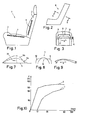
- the car seat 1 shown in FIG. 1 has a backrest 2 and a seat part 3.
- Anatomically formable supports 4, 5 are arranged both in the backrest and in the seat part.
- the supports are connected to the frame and the suspension of the car seat and each of a layer of cushioning material, not shown, for. B. polyurethane foam surrounded.
- the supports 4, 5 can be curved according to the anatomical requirements of the user, so that the spine can be supported according to its shape with an asymmetrical curvature of the support.
- the support provided in the seat part there is also the possibility of changing the seating surface in such a way that the thigh of the user is supported at the same time, the seat height also being partially adjustable at the same time.
- a support according to the invention is provided in the back part, the support 7 in the central region 8 providing greater resistance to elastic deformation than the two edge regions 9, 10.
- the Bowden cable 11 with the tension element 12 can the curvature in the direction of movement a can be changed transversely to the backrest.
- the fact that the middle part has a higher resistance to elastic deformation than the two edge parts ensures that when the trough, which serves to accommodate the back of the child, changes in width, it does not become circular, but that one of the back and chest adapted to the child's trough.
- Such a trough ensures that a child in such a seat, e.g. B.
- the pulling element can also be provided in a holding arch, which is used for support with the child's hands, wherein the holding arch can also be designed to be openable and closable.
- Such a design of a seat can also for So-called bucket seats, such as are common in sports cars, come into use.
- the Bowden cable and thus the pull element is arranged at the lower end of the backrest, so that there is no impairment of the seating comfort.
- a particularly advantageous embodiment is achieved in this way, since the backrest can be designed to widen upwards as desired.
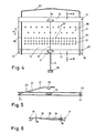
- the support 5 shown in FIG. 4 can be used not only for the backrest part of the seat in FIG. 1, but also for the seat part 3.
- the support has a plate 13 which has two mutually opposite regions 14, 15 which are arranged at the respective ends to which the tension element 12 and the hose 16 partially enveloping the tension element, and the like. between attack on the abutments formed by transverse ribs 17, 18.
- the setting is made via the handwheel 19.
- These abutments as can be seen particularly clearly in FIG. 6, are made flush with the plate and are partially circular in cross section.
- circular support bodies 20, 21 are also provided in cross section, so that when the pulling element is actuated via the handwheel 19, the support bodies are easily gliding in the abutment.
- a guide 22 is provided, which is constructed from a round steel.
- the guide is at the respective lateral ends of the abutments 17, 18, u. between.
- the guide has 26 bends 25 at the free end of the legs. How 4, the guide is essentially U-shaped.
- the base 27 of the U's has legs 28 which are bent out of the plane of the legs 26, with a crank 29 for fixing the guide in the backrest is provided.
- the support can in turn be moved along the guide either via a double Bowden cable or, for example, via a spindle. With such a movement of the support along the guide, the location of the apex can be changed in the longitudinal direction of the backrest or the seat surface.
- the wall thickness w increases in steps, u. between halves, which leads to the formation of an asymmetrical curvature when force is applied, which can be support-free in the apex, so that, for example, the apex can also change its position in the event of impact loads.
- the plate is made with three laminates 34, 35, 36 of different lengths, whereby the stepped design is obtained.
- unsaturated polyester resins for example, unsaturated polyester resins, orthophthalate polyester resins can be used, whereby glass fibers can either be oriented or can be in the form of tangled fibers. With continuous changes in material thickness, a spray compound with short fibers has proven itself.
- the material should be difficult to non-flammable and compared to other plastics, e.g. B. foam, be inert.
- a sandwich structure can also be provided.
- Another possibility of providing differently deformable areas in the plate is as in FIG. 4 shown that, for example, fewer openings 32 are arranged in area 30 than in area 31, so that area 31 is more easily deformable than area 30.
- the advantage of such openings is also that they can be made after the plate has been produced, so that there is a high degree of flexibility in the formation of the curvature.
- the plate can be cut to length from a strip by means of a punching process, the openings with different shapes being round, oval, angular, etc. being produced at the same time.
- the openings can also be made by drilling or the like. Breakthroughs also have the advantage that they also allow circulation, for example the air humidity, through the support and thus prevent perspiration.
- a support 5 is shown schematically in FIG. 7, the support being shown in different stages of curvature 5a and 5b. As can easily be seen, the left part of the support is the area which offers greater resistance to elastic deformability than the right area, so that the maximum curvature moves along line 33.
- the central region 8 has a greater resistance to elastic deformation than the two edge regions 9, 10, so that the central region remains essentially rectilinear during deformation, whereas the two lateral regions are deformed more. which creates a trough with variable width, with a flat area for receiving, for example the back, z. B. in the child seat, as shown in FIG. 3 is guaranteed.
- the Support shown in dashed lines is the support with a particularly narrow trough, whereas support shown with a full line forms a particularly wide trough.
- FIG. 9 shows a plate in cross-section in analogy to FIG. 6. In contrast to the plate according to FIG. 6, this is already shown in FIG. B. acted upon by tensile forces in the direction of movement, curved. With such a curved design, on the one hand the location and partly the shape of the curvature can be predetermined in addition to the different design of the flexibility.
- Curve 10 shows the respective forces for a specific deflection in a force / displacement diagram.
- Curve 1 corresponds to the embodiment according to FIG. 9, in which the plate is pre-curved
- curve 2 corresponds to a plate that is not pre-curved and is designed according to FIG. 6.
- the pre-curved plate requires less effort, in particular in the initial phase, in order to achieve a certain curvature.
- Pre-curved plates therefore allow less effort to be exerted, which is particularly advantageous when operated by hand in order to set the desired curvature. If it is operated by a motor, a weaker and therefore smaller motor with lower energy consumption can be used.
Landscapes
- Engineering & Computer Science (AREA)
- Aviation & Aerospace Engineering (AREA)
- Transportation (AREA)
- Mechanical Engineering (AREA)
- Chair Legs, Seat Parts, And Backrests (AREA)
- Compositions Of Macromolecular Compounds (AREA)
- Hooks, Suction Cups, And Attachment By Adhesive Means (AREA)
Applications Claiming Priority (2)
| Application Number | Priority Date | Filing Date | Title |
|---|---|---|---|
| AT0287389A AT396055B (de) | 1989-12-18 | 1989-12-18 | Anatomisch formbare stuetze |
| AT2873/89 | 1989-12-18 |
Publications (3)
| Publication Number | Publication Date |
|---|---|
| EP0434660A2 true EP0434660A2 (fr) | 1991-06-26 |
| EP0434660A3 EP0434660A3 (fr) | 1991-07-17 |
| EP0434660B1 EP0434660B1 (fr) | 1995-05-03 |
Family
ID=3541662
Family Applications (1)
| Application Number | Title | Priority Date | Filing Date |
|---|---|---|---|
| EP90890318A Expired - Lifetime EP0434660B1 (fr) | 1989-12-18 | 1990-12-10 | Support réglable anatomiquement |
Country Status (4)
| Country | Link |
|---|---|
| EP (1) | EP0434660B1 (fr) |
| AT (1) | AT396055B (fr) |
| DE (1) | DE59009013D1 (fr) |
| ES (1) | ES2077668T3 (fr) |
Cited By (5)
| Publication number | Priority date | Publication date | Assignee | Title |
|---|---|---|---|---|
| EP0698360A1 (fr) | 1994-08-10 | 1996-02-28 | Austro Investment S.A. | Support réglable anatomique, notamment support lombaire |
| WO2000046525A1 (fr) * | 1999-02-02 | 2000-08-10 | Schukra Manufacturing Inc. | Connecteur d'ensemble a cable |
| US6524024B1 (en) | 1994-03-18 | 2003-02-25 | Schukra Manufacturing, Inc. | Cable assembly connector |
| DE10322189A1 (de) * | 2003-05-16 | 2004-12-23 | Schukra Gerätebau AG | Lordosenstützkorb |
| WO2020026000A1 (fr) * | 2018-07-31 | 2020-02-06 | Safran Seats Usa Llc | Ensemble appui-tête flexible |
Families Citing this family (27)
| Publication number | Priority date | Publication date | Assignee | Title |
|---|---|---|---|---|
| AT394829B (de) | 1989-08-04 | 1992-06-25 | Schuster Wilhelm | Rueckenlehne fuer einen fahrzeugsitz, mit einer verstellbaren lendenstuetze |
| DE4320105C1 (de) | 1993-06-17 | 1994-10-13 | Ameu Management Corp | Verstellvorrichtung für ein biegeelastisches Stützelement einer Rückenlehne |
| US6805680B2 (en) | 1994-12-09 | 2004-10-19 | Schukra-Geratebau Ag | Method for providing a massage on seats, and a device for implementing this method |
| AT409711B (de) | 2000-08-07 | 2002-10-25 | Schukra Geraetebau Ag | Vorrichtung zum lageverändern und feststellen von teilen, z.b. lordosenstützen, von möbeln zum sitzen und/oder liegen |
| US6619739B2 (en) | 2001-03-01 | 2003-09-16 | L & P Property Management Company | Universal ergonomic support with self-contained actuator |
| US6758522B2 (en) | 2001-03-29 | 2004-07-06 | L&P Property Management Company | Apparatus and method for varying coefficients of friction in a variable apex back support |
| CN100486837C (zh) | 2001-10-11 | 2009-05-13 | L&P产权管理公司 | 装有动力的腰部机构 |
| US6652028B2 (en) | 2001-11-02 | 2003-11-25 | L & P Property Management | Apparatus and method for lumbar support with variable apex |
| US6676214B2 (en) | 2001-11-16 | 2004-01-13 | L & P Property Management Company | Method and apparatus for lumbar support with integrated actuator housing |
| US6779844B2 (en) | 2001-12-14 | 2004-08-24 | L&P Propety Maqnagement Company | Arching lumbar support with weight distribution surface |
| US6908152B2 (en) | 2001-12-14 | 2005-06-21 | L & P Property Management Company | Push lumbar support with flexible pressure surface |
| US6652029B2 (en) | 2001-12-20 | 2003-11-25 | L & P Property Management Company | Unitized back plate and lumbar support |
| US7083232B2 (en) | 2002-11-01 | 2006-08-01 | L&P Property Management Company | Massage apparatus and method for lumbar support |
| DE10253452A1 (de) * | 2002-11-16 | 2004-05-27 | Bayerische Motoren Werke Ag | Fahrzeugsitz |
| US6908153B2 (en) | 2002-12-02 | 2005-06-21 | L&P Property Management Company | Power lumbar support cable apparatus and method |
| US7052087B2 (en) | 2002-12-09 | 2006-05-30 | L&P Property Management Company | Method and apparatus for a scissors ergonomic support |
| US7137664B2 (en) | 2003-01-22 | 2006-11-21 | L&P Property Management Company | Automatically actuating ergonomic support system for a fold down seat |
| US6905170B2 (en) | 2003-01-22 | 2005-06-14 | L & P Property Management Company | Fold down seat lumbar support apparatus and method |
| US7140680B2 (en) | 2003-01-22 | 2006-11-28 | L&P Property Management Company | Fold down seat lumbar support apparatus and method |
| US7775595B2 (en) | 2004-02-06 | 2010-08-17 | Schukra Of North America | Drive mechanism |
| EP1771315B1 (fr) | 2004-07-30 | 2008-12-10 | L&P Property Management Company | Support lombaire modulaire |
| EP1680984B1 (fr) | 2005-01-12 | 2007-08-15 | L&P Swiss Holding Company | Dispositif de soutien lombaire et structure de siège afférante |
| EP1680983B1 (fr) | 2005-01-12 | 2012-11-28 | L&P Swiss Holding Company | Structure de siège équipé d'une unité de couplage |
| WO2007112564A1 (fr) | 2006-03-30 | 2007-10-11 | Schukra Of North America, Ltd. | Système combiné de support lombaire-rembourrage latéral |
| US7614696B2 (en) | 2006-12-11 | 2009-11-10 | Schukra Of North America | Lumbar system for climate seating |
| US7984949B2 (en) | 2007-04-24 | 2011-07-26 | Schukra Of North America | Lumbar and bolster support for second row seat |
| US7997650B2 (en) | 2008-02-22 | 2011-08-16 | Schukra Of North America | Constant pressure retreating lumbar system |
Family Cites Families (8)
| Publication number | Priority date | Publication date | Assignee | Title |
|---|---|---|---|---|
| US4153293A (en) * | 1977-09-06 | 1979-05-08 | Nepsco, Inc. | Back rest |
| DE2804703A1 (de) * | 1978-02-03 | 1979-08-09 | Fritzmeier Ag | Rueckenlehne mit hoehen- und woelbungsverstellung |
| AT368958B (de) * | 1979-01-24 | 1982-11-25 | Steyr Daimler Puch Ag | Rueckenlehne, insbesondere fuer kraftfahrzeugsitze |
| DE2947472A1 (de) * | 1979-01-24 | 1980-08-07 | Steyr Daimler Puch Ag | Rueckenlehne, insbesondere fuer kraftfahrzeugsitze |
| DE3324655C2 (de) * | 1983-07-08 | 1985-05-15 | Fa. Willibald Grammer, 8450 Amberg | Sitz mit Bandscheibenstütze |
| SE449556B (sv) * | 1983-11-09 | 1987-05-11 | Volvo Ab | Stol, exv bil-, tag- eller flygplansstol, innefattande ett i sitt ryggstod anordnat svankstod |
| DE3634500A1 (de) * | 1986-02-10 | 1987-08-20 | Wilfried Prof Dr Me Diebschlag | Sitz, insbesondere autositz |
| DE8702174U1 (de) * | 1987-02-12 | 1987-04-30 | Kemmann & Koch, 5620 Velbert | Verstellbare Rückenlehne |
-
1989
- 1989-12-18 AT AT0287389A patent/AT396055B/de not_active IP Right Cessation
-
1990
- 1990-12-10 DE DE59009013T patent/DE59009013D1/de not_active Expired - Fee Related
- 1990-12-10 ES ES90890318T patent/ES2077668T3/es not_active Expired - Lifetime
- 1990-12-10 EP EP90890318A patent/EP0434660B1/fr not_active Expired - Lifetime
Cited By (7)
| Publication number | Priority date | Publication date | Assignee | Title |
|---|---|---|---|---|
| US6524024B1 (en) | 1994-03-18 | 2003-02-25 | Schukra Manufacturing, Inc. | Cable assembly connector |
| EP0698360A1 (fr) | 1994-08-10 | 1996-02-28 | Austro Investment S.A. | Support réglable anatomique, notamment support lombaire |
| WO2000046525A1 (fr) * | 1999-02-02 | 2000-08-10 | Schukra Manufacturing Inc. | Connecteur d'ensemble a cable |
| DE10322189A1 (de) * | 2003-05-16 | 2004-12-23 | Schukra Gerätebau AG | Lordosenstützkorb |
| DE10322189B4 (de) * | 2003-05-16 | 2009-04-09 | Schukra Gerätebau AG | Lordosenstützkorb |
| WO2020026000A1 (fr) * | 2018-07-31 | 2020-02-06 | Safran Seats Usa Llc | Ensemble appui-tête flexible |
| US11192654B2 (en) | 2018-07-31 | 2021-12-07 | Safran Seats Usa Llc | Flexible headrest assembly |
Also Published As
| Publication number | Publication date |
|---|---|
| EP0434660B1 (fr) | 1995-05-03 |
| AT396055B (de) | 1993-05-25 |
| ATA287389A (de) | 1992-10-15 |
| DE59009013D1 (de) | 1995-06-08 |
| EP0434660A3 (fr) | 1991-07-17 |
| ES2077668T3 (es) | 1995-12-01 |
Similar Documents
| Publication | Publication Date | Title |
|---|---|---|
| EP0434660B1 (fr) | Support réglable anatomiquement | |
| EP0698360B1 (fr) | Support réglable anatomique, notamment support lombaire | |
| EP0006840B1 (fr) | Support élastique flexible | |
| DE60110591T2 (de) | Wirbelsäulenstütze für fahrzeugsitze | |
| DE69907489T2 (de) | Sitzaufhängungseinrichtung | |
| DE19942351B4 (de) | Sitztiefeneinstellvorrichtung für einen Fahrzeugsitz | |
| EP1082233B1 (fr) | Dossier à courbure adaptable, notamment élément de soutien lordotique, pour sièges et chaises longues de tout type | |
| DE2751608C2 (de) | Orthopädisches Stützkorsett | |
| DE1554084C3 (de) | Sitz, insbesondere Kraftfahrzeugsitz | |
| DE8007534U1 (de) | Lasttragender rahmen insbesondere fuer die ruecklehne eines fahrzeugsitzes | |
| DE2364797A1 (de) | Verstellbare sitzanordnung fuer ein fahrzeug | |
| DE69305102T2 (de) | Sitz mit Lendenstütze, insbesondere für Kraftfahrzeuge | |
| EP1501389A1 (fr) | Garniture de siege et son procede de production | |
| WO2006133809A1 (fr) | Appui dorsolombaire | |
| EP1277612B1 (fr) | Siège pour automobiles ou équivalents | |
| DE9300369U1 (de) | Flächiger Polsterkörper aus Schaumstoff, insbesondere Matratze | |
| EP0397069A1 (fr) | Sommier à lattes avec des lattes intermédiaires supportées élastiquement | |
| EP3826511B1 (fr) | Caillebotis | |
| DE602005004111T2 (de) | Trägerstruktur für einen Sitz mit einer Tischfunktion und entsprechende Sitzfederungsanordnung | |
| DE19850121B4 (de) | Justierbare Lordosenstütze | |
| DE10355659A1 (de) | Lordosenstütze | |
| DE102010048643A1 (de) | Armauflage für ein Innenraumteil eines Kraftwagens | |
| DE202020102861U1 (de) | Bettunterbau | |
| DE3531076C2 (fr) | ||
| DE3128894A1 (de) | Matratze mit einem starren rahmen |
Legal Events
| Date | Code | Title | Description |
|---|---|---|---|
| PUAI | Public reference made under article 153(3) epc to a published international application that has entered the european phase |
Free format text: ORIGINAL CODE: 0009012 |
|
| PUAL | Search report despatched |
Free format text: ORIGINAL CODE: 0009013 |
|
| AK | Designated contracting states |
Kind code of ref document: A2 Designated state(s): BE CH DE DK ES FR GB GR IT LI LU NL SE |
|
| AK | Designated contracting states |
Kind code of ref document: A3 Designated state(s): BE CH DE DK ES FR GB GR IT LI LU NL SE |
|
| RAP1 | Party data changed (applicant data changed or rights of an application transferred) |
Owner name: AUSTRO INVEST S.A. |
|
| 17P | Request for examination filed |
Effective date: 19911211 |
|
| 17Q | First examination report despatched |
Effective date: 19930429 |
|
| GRAA | (expected) grant |
Free format text: ORIGINAL CODE: 0009210 |
|
| AK | Designated contracting states |
Kind code of ref document: B1 Designated state(s): BE CH DE DK ES FR GB GR IT LI LU NL SE |
|
| PG25 | Lapsed in a contracting state [announced via postgrant information from national office to epo] |
Ref country code: NL Free format text: LAPSE BECAUSE OF NON-PAYMENT OF DUE FEES Effective date: 19950503 Ref country code: GR Free format text: LAPSE BECAUSE OF FAILURE TO SUBMIT A TRANSLATION OF THE DESCRIPTION OR TO PAY THE FEE WITHIN THE PRESCRIBED TIME-LIMIT Effective date: 19950503 Ref country code: DK Effective date: 19950503 Ref country code: BE Effective date: 19950503 |
|
| REF | Corresponds to: |
Ref document number: 59009013 Country of ref document: DE Date of ref document: 19950608 |
|
| ITF | It: translation for a ep patent filed | ||
| PG25 | Lapsed in a contracting state [announced via postgrant information from national office to epo] |
Ref country code: SE Effective date: 19950803 |
|
| ET | Fr: translation filed | ||
| GBT | Gb: translation of ep patent filed (gb section 77(6)(a)/1977) |
Effective date: 19950807 |
|
| NLV1 | Nl: lapsed or annulled due to failure to fulfill the requirements of art. 29p and 29m of the patents act | ||
| REG | Reference to a national code |
Ref country code: ES Ref legal event code: FG2A Ref document number: 2077668 Country of ref document: ES Kind code of ref document: T3 |
|
| RAP2 | Party data changed (patent owner data changed or rights of a patent transferred) |
Owner name: BERNDORF AUTOMOTIVE PRODUKTE GES.M.B.H. |
|
| PG25 | Lapsed in a contracting state [announced via postgrant information from national office to epo] |
Ref country code: LU Free format text: LAPSE BECAUSE OF NON-PAYMENT OF DUE FEES Effective date: 19951231 Ref country code: LI Effective date: 19951231 Ref country code: CH Effective date: 19951231 |
|
| PLBE | No opposition filed within time limit |
Free format text: ORIGINAL CODE: 0009261 |
|
| STAA | Information on the status of an ep patent application or granted ep patent |
Free format text: STATUS: NO OPPOSITION FILED WITHIN TIME LIMIT |
|
| 26N | No opposition filed | ||
| REG | Reference to a national code |
Ref country code: CH Ref legal event code: PL |
|
| ITPR | It: changes in ownership of a european patent |
Owner name: CAMBIO TIT.RE EPO;BERNDORF AUTOMOTIVE PRODUKTE GES |
|
| REG | Reference to a national code |
Ref country code: GB Ref legal event code: 732E |
|
| REG | Reference to a national code |
Ref country code: FR Ref legal event code: CD |
|
| REG | Reference to a national code |
Ref country code: ES Ref legal event code: PC2A |
|
| PGFP | Annual fee paid to national office [announced via postgrant information from national office to epo] |
Ref country code: GB Payment date: 20011126 Year of fee payment: 12 |
|
| PGFP | Annual fee paid to national office [announced via postgrant information from national office to epo] |
Ref country code: DE Payment date: 20011211 Year of fee payment: 12 |
|
| PGFP | Annual fee paid to national office [announced via postgrant information from national office to epo] |
Ref country code: FR Payment date: 20011212 Year of fee payment: 12 |
|
| PGFP | Annual fee paid to national office [announced via postgrant information from national office to epo] |
Ref country code: ES Payment date: 20011218 Year of fee payment: 12 |
|
| REG | Reference to a national code |
Ref country code: GB Ref legal event code: IF02 |
|
| PG25 | Lapsed in a contracting state [announced via postgrant information from national office to epo] |
Ref country code: GB Free format text: LAPSE BECAUSE OF NON-PAYMENT OF DUE FEES Effective date: 20021210 |
|
| PG25 | Lapsed in a contracting state [announced via postgrant information from national office to epo] |
Ref country code: ES Free format text: LAPSE BECAUSE OF NON-PAYMENT OF DUE FEES Effective date: 20021211 |
|
| PG25 | Lapsed in a contracting state [announced via postgrant information from national office to epo] |
Ref country code: DE Free format text: LAPSE BECAUSE OF NON-PAYMENT OF DUE FEES Effective date: 20030701 |
|
| GBPC | Gb: european patent ceased through non-payment of renewal fee | ||
| PG25 | Lapsed in a contracting state [announced via postgrant information from national office to epo] |
Ref country code: FR Free format text: LAPSE BECAUSE OF NON-PAYMENT OF DUE FEES Effective date: 20030901 |
|
| REG | Reference to a national code |
Ref country code: FR Ref legal event code: ST |
|
| REG | Reference to a national code |
Ref country code: ES Ref legal event code: FD2A Effective date: 20021211 |
|
| PG25 | Lapsed in a contracting state [announced via postgrant information from national office to epo] |
Ref country code: IT Free format text: LAPSE BECAUSE OF NON-PAYMENT OF DUE FEES;WARNING: LAPSES OF ITALIAN PATENTS WITH EFFECTIVE DATE BEFORE 2007 MAY HAVE OCCURRED AT ANY TIME BEFORE 2007. THE CORRECT EFFECTIVE DATE MAY BE DIFFERENT FROM THE ONE RECORDED. Effective date: 20051210 |