EP0434672B1 - Infusionspumpe - Google Patents
Infusionspumpe Download PDFInfo
- Publication number
- EP0434672B1 EP0434672B1 EP88905585A EP88905585A EP0434672B1 EP 0434672 B1 EP0434672 B1 EP 0434672B1 EP 88905585 A EP88905585 A EP 88905585A EP 88905585 A EP88905585 A EP 88905585A EP 0434672 B1 EP0434672 B1 EP 0434672B1
- Authority
- EP
- European Patent Office
- Prior art keywords
- syringe
- drive
- actuator
- pump
- arm
- Prior art date
- Legal status (The legal status is an assumption and is not a legal conclusion. Google has not performed a legal analysis and makes no representation as to the accuracy of the status listed.)
- Expired - Lifetime
Links
- 238000001802 infusion Methods 0.000 title abstract description 35
- 239000012530 fluid Substances 0.000 claims description 13
- 230000004044 response Effects 0.000 claims description 3
- 239000003814 drug Substances 0.000 abstract description 13
- 229940079593 drug Drugs 0.000 abstract description 13
- 230000009467 reduction Effects 0.000 abstract description 4
- 238000003780 insertion Methods 0.000 abstract 1
- 230000037431 insertion Effects 0.000 abstract 1
- 230000001276 controlling effect Effects 0.000 description 9
- 230000007246 mechanism Effects 0.000 description 3
- 230000009471 action Effects 0.000 description 2
- 230000008859 change Effects 0.000 description 2
- 230000006835 compression Effects 0.000 description 2
- 238000007906 compression Methods 0.000 description 2
- 238000010586 diagram Methods 0.000 description 2
- 230000006870 function Effects 0.000 description 2
- 238000000034 method Methods 0.000 description 2
- 229940124326 anaesthetic agent Drugs 0.000 description 1
- 230000003444 anaesthetic effect Effects 0.000 description 1
- 230000008901 benefit Effects 0.000 description 1
- 239000008280 blood Substances 0.000 description 1
- 210000004369 blood Anatomy 0.000 description 1
- 238000004159 blood analysis Methods 0.000 description 1
- 238000012790 confirmation Methods 0.000 description 1
- 238000010276 construction Methods 0.000 description 1
- 238000009795 derivation Methods 0.000 description 1
- 230000006872 improvement Effects 0.000 description 1
- 230000003993 interaction Effects 0.000 description 1
- 239000007788 liquid Substances 0.000 description 1
- 239000004973 liquid crystal related substance Substances 0.000 description 1
- 238000005259 measurement Methods 0.000 description 1
- 238000012856 packing Methods 0.000 description 1
- 238000005086 pumping Methods 0.000 description 1
- 230000001105 regulatory effect Effects 0.000 description 1
- 230000008439 repair process Effects 0.000 description 1
- 238000012360 testing method Methods 0.000 description 1
Images


Classifications
-
- A—HUMAN NECESSITIES
- A61—MEDICAL OR VETERINARY SCIENCE; HYGIENE
- A61M—DEVICES FOR INTRODUCING MEDIA INTO, OR ONTO, THE BODY; DEVICES FOR TRANSDUCING BODY MEDIA OR FOR TAKING MEDIA FROM THE BODY; DEVICES FOR PRODUCING OR ENDING SLEEP OR STUPOR
- A61M5/00—Devices for bringing media into the body in a subcutaneous, intra-vascular or intramuscular way; Accessories therefor, e.g. filling or cleaning devices, arm-rests
- A61M5/14—Infusion devices, e.g. infusing by gravity; Blood infusion; Accessories therefor
- A61M5/142—Pressure infusion, e.g. using pumps
- A61M5/145—Pressure infusion, e.g. using pumps using pressurised reservoirs, e.g. pressurised by means of pistons
- A61M5/1452—Pressure infusion, e.g. using pumps using pressurised reservoirs, e.g. pressurised by means of pistons pressurised by means of pistons
- A61M5/1456—Pressure infusion, e.g. using pumps using pressurised reservoirs, e.g. pressurised by means of pistons pressurised by means of pistons with a replaceable reservoir comprising a piston rod to be moved into the reservoir, e.g. the piston rod is part of the removable reservoir
-
- A—HUMAN NECESSITIES
- A61—MEDICAL OR VETERINARY SCIENCE; HYGIENE
- A61M—DEVICES FOR INTRODUCING MEDIA INTO, OR ONTO, THE BODY; DEVICES FOR TRANSDUCING BODY MEDIA OR FOR TAKING MEDIA FROM THE BODY; DEVICES FOR PRODUCING OR ENDING SLEEP OR STUPOR
- A61M5/00—Devices for bringing media into the body in a subcutaneous, intra-vascular or intramuscular way; Accessories therefor, e.g. filling or cleaning devices, arm-rests
- A61M5/14—Infusion devices, e.g. infusing by gravity; Blood infusion; Accessories therefor
- A61M5/142—Pressure infusion, e.g. using pumps
- A61M5/145—Pressure infusion, e.g. using pumps using pressurised reservoirs, e.g. pressurised by means of pistons
- A61M5/1452—Pressure infusion, e.g. using pumps using pressurised reservoirs, e.g. pressurised by means of pistons pressurised by means of pistons
- A61M5/1458—Means for capture of the plunger flange
-
- A—HUMAN NECESSITIES
- A61—MEDICAL OR VETERINARY SCIENCE; HYGIENE
- A61M—DEVICES FOR INTRODUCING MEDIA INTO, OR ONTO, THE BODY; DEVICES FOR TRANSDUCING BODY MEDIA OR FOR TAKING MEDIA FROM THE BODY; DEVICES FOR PRODUCING OR ENDING SLEEP OR STUPOR
- A61M5/00—Devices for bringing media into the body in a subcutaneous, intra-vascular or intramuscular way; Accessories therefor, e.g. filling or cleaning devices, arm-rests
- A61M5/14—Infusion devices, e.g. infusing by gravity; Blood infusion; Accessories therefor
- A61M5/168—Means for controlling media flow to the body or for metering media to the body, e.g. drip meters, counters ; Monitoring media flow to the body
- A61M5/16831—Monitoring, detecting, signalling or eliminating infusion flow anomalies
- A61M5/16854—Monitoring, detecting, signalling or eliminating infusion flow anomalies by monitoring line pressure
-
- Y—GENERAL TAGGING OF NEW TECHNOLOGICAL DEVELOPMENTS; GENERAL TAGGING OF CROSS-SECTIONAL TECHNOLOGIES SPANNING OVER SEVERAL SECTIONS OF THE IPC; TECHNICAL SUBJECTS COVERED BY FORMER USPC CROSS-REFERENCE ART COLLECTIONS [XRACs] AND DIGESTS
- Y10—TECHNICAL SUBJECTS COVERED BY FORMER USPC
- Y10S—TECHNICAL SUBJECTS COVERED BY FORMER USPC CROSS-REFERENCE ART COLLECTIONS [XRACs] AND DIGESTS
- Y10S128/00—Surgery
- Y10S128/01—Motorized syringe
-
- Y—GENERAL TAGGING OF NEW TECHNOLOGICAL DEVELOPMENTS; GENERAL TAGGING OF CROSS-SECTIONAL TECHNOLOGIES SPANNING OVER SEVERAL SECTIONS OF THE IPC; TECHNICAL SUBJECTS COVERED BY FORMER USPC CROSS-REFERENCE ART COLLECTIONS [XRACs] AND DIGESTS
- Y10—TECHNICAL SUBJECTS COVERED BY FORMER USPC
- Y10S—TECHNICAL SUBJECTS COVERED BY FORMER USPC CROSS-REFERENCE ART COLLECTIONS [XRACs] AND DIGESTS
- Y10S128/00—Surgery
- Y10S128/12—Pressure infusion
Definitions
- This invention relates to improvements in pumps far the delivery of drugs and other fluids in metered quantities.
- a wide range of controlled infusion pumps which are adapted to deliver drugs from a syringe are currently available and are widely use for a number of purposes in the medical field.
- Several of these pumps have a limited ability to "recognise” one or more standard syringe sizes (Atom 235 and Terufusion STC-521).
- Other pumps are highly programmable to accept a range of different standard syringes (Medfusion Systems - Model 1001, Vial Medical Program 3 and Sky Electronics - PS2000).
- a pump for the delivery of controlled amounts of fluid from a syringe having a body and a plunger comprising: means for receiving and locating the body of the syringe; syringe actuator means for engaging the plunger of the syringe held by said receiving and locating means; means for generating an electrical signal representing the position of said syringe actuator means; drive means connected to said actuator means to move the plunger into the syringe to deliver the fluid, said drive means including a permanently maintained connection between said actuator means and said means for generating said electrical signal representing the position of said actuator means; means for controlling said drive means; a movable arm for contacting the body of the syringe when held by said receiving and locating means; means for generating an electrical signal corresponding to the position of said arm when contacting the syringe body to provide a signal representative of the diameter of the syringe; means for inputting calibration data to said drive controlling means by storing the position of said actuator
- the infusion pump embodying the present invention will be seen to comprise a casing 1 within which the drive system embodying the invention is located, the casing 1 including a syringe cradle 2 having a centrally located groove 3 for locating the body of a syringe S (Fig. 3), and a slot 4 for receiving and locating the syringe flange.
- the syringe S is held in position in the groove 3 by means of a spring loaded syringe clamping arm 5 which is pivotally mounted within a housing 6 extending upwardly from the cradle 2.
- a syringe actuator 7 is mounted for sliding movement along a pair of guide rods 8 supported by the casing 1 and is driven by a driving mechanism located within the casing 1, and which will be described in greater detail below, to engage the plunger of the syringe S to cause the fluid contained in the syringe to be administered in a manner controlled by the central controlling system (Fig. 2) of the pump.
- the actuator 7 carries a proximity micro switch 9 and a clutch releasing button 10.
- the proximity microswitch 9 detects when the actuator 7 initially engages the plunger of the syringe so that the pump controller is made aware that contact with the plunger has occurred.
- the clutch releasing button 10 disengages the drive motor from the drive system to allow the actuator to be freely moved between its operating extremities for the purposes described further below.
- the infusion pump casing 1 includes a key pad 11 including the usual array of numerical keys, an enter key, a clear key and a stop key.
- a key pad 11 including the usual array of numerical keys, an enter key, a clear key and a stop key.
- several other keys 12 are also provided on the front panel, including:
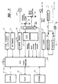
- the central microprocessor 20 is typically a Z80 type and is under the control of EPROM 21, RAM 22, EEPROM 23, a key pad 11 and a clamping arm potentiometer 24 and a syringe actuator position potentiometer 25, via multiplexer 26 and analogue to digital converter 27.
- the controlling microprocessor 20 in turn controls the operation of a drive stepper motor 28 via a stepper driver circuit 29, the LCD display 13, an alarm buzzer 30 and a printer (not shown) via UART 31.
- the stepper drive circuit 29 is supplied by a power supply 32 which provides a regulated 5 volt rail and an eight volt rail for the stepper driver from a chargeable battery.
- the EPROM 21 contains the variable programmed information on which the pump controller operates, including a series of drug infusion profiles relating to various drugs to be infused.
- the RAM 22 constitutes the active memory of the control microprocessor 20 while the EEPROM 23 contains the fixed programme data, and is capable of storing data relating to the position of the clamping arm 5 when syringes S of predetermined volumes are loaded into the cradle 2.
- the controlling microprocessor 20 also receives electrical signals from microswitches which detect manual disengagement of the clutch, contact between the micro switch 9 and the plunger of the syringe S and unintended disengagement of the clutch caused by the occurrence of an occlusion preventing infusion.
- the syringe clamping arm 5 extends from a support 39 carried by a rotatably mounted shaft 40 supporting a notched cam 41 which is positioned to operate an on/off microswitch 42 when the clamping arm 5 is moved from its rest or lowest position to actuate the control system for the pump.
- the support is in the form of a cam which bears against a spring loaded lever (not shown) to supply a biasing force which holds the clamping arm 5 in engagement with a syringe carried by the cradle 2.
- the cam support 39 is arranged to be in the over-centre position when the clamping arm 5 is raised to its highest position. This enables the operator to position the clamping arm 5 at its highest point to enable loading of a syringe into the cradle 2.
- the shaft 40 further carries a gear wheel 43 which meshes with a pinion 44 carried by the shaft 45 of the potentiometer 24.
- the gear ratio of the gear 43 and pinion 44 which is usually about 4:1 or 5:1.
- the shaft 45 also carries a hair spring or watch spring 46 which has one end anchored to the casing 6 and the other end anchored to the shaft 45.
- the spring biases the pinion 44 in the required direction to prevent any backlash between the gears 43 and 44 being transmitted to the potentiometer 24.
- the shape of the clamping arm 5 is selected so that, for syringes in the range 10 to 50 ml in the syringe cradle 2, an approximately straight line relationship exists between the diameter of the syringe and the resistance of the potentiometer 24. In this way, the position of the clamping arm 5 is able to produce a voltage signal which provides an indication to the controlling computer 20 of the diameter of the syringe.
- clamping arm potentiometer voltage or "diameter" information corresponding to four selected syringe sizes, such as, 10, 20, 30 and 50 ml, may be stored in the EEPROM 23 either before sale, during sale or after sale.
- a diameter voltage signal is generated by the potentiometer 24 and is transmitted via the multiplexer 26 and the analog to digital converter 27 to the central controlling microprocessor 20.
- This diameter signal is compared with the programmed diameter information contained in the EEPROM 23, which will usually be in the form of a look-up table, and if the diameter signal corresponds to one of the standard diameters within a reasonable tolerance such as ⁇ 2.5%, the controller 20 will cause the corresponding volume of that syringe to be displayed on the LCD display 13 so that the operator may confirm that the volume displayed is the correct volume of the syringe which has been inserted by pressing the YES button. Once confirmation has been entered by the operator, the pump is ready to operate according to a selected infusion rate profile in the general manner described in the co-pending applications referred to above.
- non-standard a syringe for which the pump has not previously been calibrated
- the drive system comprises the stepping motor 28, which is horizontally mounted on a vertical support plate 50 having a horizontal portion 51 which is attached to the frame 52 which supports the cover 1.
- the stepper motor 28 is an ESCAP step motor P310, which has been found to be particularly suitable for the present purpose, and superior in operation to other stepper motors. While the use of a stepper motor, and particularly the above stepper motor, is particularly preferred since it enables highly accurate and rapid positioning of the drive system and therefore highly accurate and fast operation of the infusion pump, it should be appreciated that other forms of motor may be used to achieve acceptable results.
- a worm gear 53 is fixed to the output shaft of the stepper motor 28and is supported by a bearing plate 54 attached to the plate portion 51.
- the worm gear 53 meshes with a worm wheel 55 having a splined hub or pinion 56, the worm wheel 55 and pinion 56 being supported in a bearing 57 mounted on the frame 52 and a bearing 58 mounted in an overlying support plate 59 attached to the plate 50.
- the support plate 50 and the frame portion 52 are in the preferred embodiment formed as a removable unit, to enable the motor 50, worm gear 53 and the worm wheel 55 to be separated as a unit to enable easy adjustment, repair or replacement.
- An output reduction gear 60 meshes with the splined hub 56 and is drivingly attached to a drive head 61 via a sprag clutch 62.
- the sprag clutch 62 is of known construction and includes interengaged tooth elements 63,64 normally held in engagement with each other by means of a compression spring 65.
- the biasing force applied by the compression spring 65 is adjustable by means of packing washers 66 to vary the load at which the clutch 62 will automatically disengage when an undesirable over-pressure develops in the infusion line for the syringe S.
- the drive head 61 is supported by the frame 52 and by a saddle frame 67 carrying a bearing 68 supporting the uppermost end of the drive head 61.
- the sprag clutch 62 is also manually releasable by moving the lower most toothed element 64 against the action of the spring 65 by means of a lever arm 69 positioned between the frame 52 and an actuating sleeve 70 surrounding the clutch elements 63,64.
- the lever 69 is connected via a linkage 71 to a pivoted bar 72 which is pivoted by operation of the clutch release button 10 carried by the syringe actuator 7.
- the mechanism for achieving clutch release is essentially as described in the co-pending application referred to above, although only one tube is used to transmit the clutch releasing movement.
- the button 10 is positioned to engage a radial arm 90 connected to one of the tubes 89 surrounding guide rods 8.
- the tube 89 is rotatable within the actuator 7 (and within slider 88) and carries a drive release cam 90 which is positioned to engage the pivoted bar 72 when the tube 89 rotates in response to movement of arm 90 caused by manual depression of button 10.
- a microswitch 73 is positioned between the frame 52 and the uppermost face of the out put gear 60 so that an electrical signal is created whenever the sprag clutch 62 is partially or fully disengaged. While the microswitch 73 is in the present embodiment mounted on the output gear 60, it may be more conveniently located within the sprag clutch 62 itself. Furthermore, in order to distinguish between clutch disengagements caused by operation of the clutch release button 10 and clutch disengagements caused by clutch overload, such as would occur in the event of an occlusion, a further microswitch 73a is positioned adjacent to the pivoted bar 72 to detect operation of the clutch release mechanism before clutch release occurs. These different inputs to the microprocessor 20 are labelled “manual override” and “occlusion sensor”. The input labelled "head engaged" inputs signals generated by the microswitch 9.
- the drive head 61 includes a central toothed portion 82 which is drivingly engaged by a toothed drive belt 83 which engages a further drive head 84, similar to the drive head 61, mounted for rotation at the opposite end of the frame 52.
- the shaft of the drive head 84 is connected to a potentiometer 25 by means of which the position of the drive belt 83 is accurately monitored at all times.
- the drive belt 83 is permanently connected to syringe actuator 7 by means of a belt clamp 86 having a connector plate 87 which is in turn attached to a slider 88 connected to the syringe actuator 7 by a pair of tubes 89, the assembly being slidably mounted on the guide rods 8 carried by the casing 1 and the syringe cradle 2.
- the potentiometer 25 is at all times able to accurately sense the position of the syringe actuator 7, even where the drive clutch 62 is disconnected by means of depression of the button 10 and the syringe actuator 7 is moved freely along its guide rods 8 to perform a manual infusion or to programme the controller to operate with a non-standard syringe.
- the controller will detect the presence of a non-standard syringe in the syringe cradle 2 and will advise the operator via the LCD display 13 that programming is required before infusion may proceed.
- an empty syringe of the required volume is first loaded into the syringe cradle 2 and the clamping arm 5 lowered.
- the syringe actuator 7 is then slid along its guide rods 8 after releasing the clutch by means of button 10.
- the controller will then move the syringe actuator 7 until the microswitch 9 closes indicating that contact with the syringe plunger has occurred.
- the position of the syringe actuator 7 required to empty the desired syringe is indicated by the potentiometer 25 and the controller 20 receives this data via the multiplexer 26 and the analog to digital converter 27.
- the empty syringe is then removed and the syringe actuator 7 returned to its rest position.
- a full syringe is then loaded into the syringe cradle 2 and the clamping arm 5 lowered.
- the syringe actuator 7 is then advanced either manually, or under the action of the controller until the microswitch 9 contacts the syringe plunger.
- the starting position of the syringe actuator 7 prior to infusion occurring is then input to the controller 20 from the potentiometer 25.
- the controller causes the LCD display 13 to request the operator to input the volume of the non-standard syringe whereupon the necessary delivery factor is calculated by dividing that volume by the distance measurement derived from the data relating to the respective positions of the syringe actuator 7 described above.
- the controller is then ready to perform the desired infusion profile using the last programmed non-standard syringe.
- only four calibrations may be stored in the look-up table, and if a further non-standard syringe is to be used, the data relating to that syringe will replace one of the previously input 'diameters'.
- the ability to store syringe 'diameters' may be expanded if desired although it is currently thought that four should be sufficient.
- microswitch 42 causes the controller to be powered up and the LCD display 13 displays the message: LOAD FILLED SYRINGE AND LOWER CLAMP If the syringe is a "standard” syringe, that is, one which has previously been calibrated and has its "diameter” reading in the look-up table contained in EEPROM 23, and assuming the syringe is a 60 mL syringe containing 50 mL of fluid, the display will register the message: If the operator is satisfied with the estimated volume, and presses the YES button, the display 13 will register: If a new infusion is required, the operator presses the YES button and the display 13 reads: FIXED OR PROGRAMMED?
- the display 13 will request the required rate to be input using the key pad 11. If the operator selects programmed, the display 13 requests the operator to input the desired drug and patient data in a manner similar to that described in the co-pending application referred to above.
- the following display appears: If the operator enters the correct volume and it is within ⁇ 2.5% of 50 mL the system will allow infusion to proceed. If the entered volume is outside ⁇ 2.5%, or if the "clear" button is pressed, the following display appears: The controller moves the syringe actuator 7 towards the plunger until the microswitch 9 closes. The voltage reading from the potentiometer 24 is entered into EEPROM 23 in the look-up table at the diameter value closest to it.
- the voltage from the potentiometer 25 is entered into the look-up table and the display 13 then reads:
- the controller moves the syringe actuator 7 into engagement with the plunger of the filled syringe until the switch 9 closes at which time the voltage from the potentiometer 25 is entered into EEPROM 23.
- the "delivery factor" resulting from the volume and position data referred to above is calculated and the display 13 reads: The operator then proceeds as described above.
- the infusion pump embodying the present invention is, in addition to the functions described above, also capable of performing each of the functions described in greater detail in the co-pending patent applications referred to above.
- the infusion pump embodying the invention reference should be had to the description and drawings contained in the specifications accompanying those applications.
- the preferred embodiment of the drive system is designed to provide a total reduction ratio of 1000:1 in a particularly compact and simple manner from an engineering point of view.
- the arrangement described enables the infusion pump to deliver fluids within the range 0.1ml/hr to 1500ml/hr without any recoil or drive integrity problems.
- commercially available infusion pumps have delivery rate ranges of the order of 0.1ml/hr to 150ml/hr which is insufficient for the drug infusion control system described in greater detail in the co-pending applications
- the present drive system is capable of actuating the syringe at rates up to 10 times the rate achieved by existing devices.
- the particularly preferred stepper motor selected for use in the present embodiment enables adequate torque to be maintained at speed ranges up to 3000rpm, thus facilitating the high delivery rates referred to above.
- the use of a sprag clutch as the clutch means is desirable since it spreads the load over a large number of teeth and minimizes wear.
- the spring loading of the sprag clutch permits adjustment of the disengagement force to suit varying requirements.
- the use of a splined hub or pinion enables the sprag clutch to be suitably located and to permit disengagement of the clutch under load.
- the infusion pump and drive system will work equally well in either direction and accordingly the pump may be used to withdraw liquids as well as deliver them.
- certain types of blood analysis require rapid withdrawal of a quantity of blood to be analysed and the drive system according to the above embodiment would enable such rapid withdrawal to be achieved.
- the pump may be used to pump fluids other than drugs.
Landscapes
- Health & Medical Sciences (AREA)
- Vascular Medicine (AREA)
- Engineering & Computer Science (AREA)
- Anesthesiology (AREA)
- Biomedical Technology (AREA)
- Heart & Thoracic Surgery (AREA)
- Hematology (AREA)
- Life Sciences & Earth Sciences (AREA)
- Animal Behavior & Ethology (AREA)
- General Health & Medical Sciences (AREA)
- Public Health (AREA)
- Veterinary Medicine (AREA)
- Infusion, Injection, And Reservoir Apparatuses (AREA)
Claims (4)
- Eine Pumpe für die Abgabe von kontrollierten Mengen eines Fluids aus einer einen Körper und einen Kolben enthaltenden Spritze, die folgendes aufweist:
Mittel (3) für die Aufnahme und Anordnung des Körpers der Spritze;
Mittel (7) für die Betätigung der Spritze, um den Kolben der von den Mitteln für die Aufnahme und Anordnung gehaltenen Spritze zu erfassen;
Mittel (25) für die Erzeugung eines elektrischen Signals, welches die Position der Mittel für die Betätigung der Spritze repräsentiert;
Mittel für den Antrieb (28, 83, 89), die mit diesen Mitteln für die Betätigung verbunden sind, um den Kolben in der Spritze im Hinblick auf die Abgabe von Fluid zu bewegen, wobei diese Mittel für den Antrieb eine permanente Verbindung (83, 86, 88, 89) zwischen den Mitteln (7) für die Betätigung und den Mitteln (25) für die Erzeugung eines elektrischen Signals enthalten, welches die Position dieser Betätigungsmittel repräsentiert;
Mittel (20) für die Kontrolle der Mittel für den Antrieb;
einen beweglichen Arm (5) für die Berührung des Körpers der Spritze, während sie von den Mitteln für die Aufnahme und Anordnung gehalten wird;
Mittel (24) für die Erzeugung eines elektrischen Signals, welches der Position dieses Armes entspricht, wenn er den Körper der Spritze berührt, um ein Signal abzugeben, welches den Durchmesser der Spritze repräsentiert;
Mittel (26, 27) für die Eingabe von Eichdaten in das Kontrollmittel (20) der Mittel für den Antrieb durch Speicherung der Position der Mittel für die Betätigung, wenn sie mit dem Kolben der leeren Spritze in Eingriff stehen, und durch Speicherung der Position dieser Mittel für die Betätigung, wenn sie mit dem Körper der befüllten Spritze in Eingriff stehen;
Mittel (11), die es dem Benutzer erlauben, das Volumen der Spritze einzugeben; und
Mittel (20) für eine Berechnung auf der Grundlage der gespeicherten Positionen der Mittel für die Betätigung und des von dem Benutzer eingegebenen Volumens der Spritze eines Abgabefaktors, welcher von dem Mitttel für die Steuerung des Antriebes verwendet wird, um die Abgabe des in der Spritze enthaltenen Fluids mit einer bestimmten Abgaberate zu kontrollieren;
dadurch gekennzeichnet, daß
die Pumpe weiterhin folgendes aufweist:
Speichermittel (21-23) für die Speicherung von Daten, die sich auf einen oder mehrere Spritzendurchmesser und die entsprechende Information über den Abgabefaktor beziehen;
logische Mittel (20), um festzustellen, ob der Wert des der Position des Armes entsprechenden elektrischen Signals einem Spritzendurchmesser entspricht, welcher in den gespeicherten Daten enthalten ist, und für die Abgabe eines Auslaßsignals, welches das Ergebnis dieser Bestimmung repräsentiert; und
Mittel (20), die auf das für eine positive Bestimmung repräsentative Signal reagieren, um aus den Speichermitteln (21-23) einen Abgabefaktor zu entnehmen, welcher dem Durchmesser der Spritze entspricht;
wobei die Eingabemittel (26, 27) für die Eichdaten so konzipiert sind, daß sie diese Eichdaten als Reaktion auf das für eine negative Bestimmung repräsentative Auslaßsignal eingeben. - Pumpe nach Anspruch 1, in der die Bewegung des beweglichen Armes (5) eine entsprechende Bewegung einer Einlaßwelle (45) eines Potentiometers (24) erzeugt, um das der Position dieses Armes entsprechende elektrische Signal zu erzeugen, und in der Getriebemittel (43, 44) zwischen diesem Arm und diesem Potentiometer angeordnet sind, um die Anzahl der Umdrehungen der Einlaßwelle zu erhöhen, die durch die Bewegung des Armes bewirkt werden.
- Pumpe nach Anspruch 2, die weiterhin Mittel (46) für die Vorspannung der Getriebemittel (43, 44) in die Richtung aufweist, welche die Bewegung der Einlaßwelle (45) reduziert, die durch ein Getriebespiel verursacht wird.
- Pumpe nach einem der Ansprüche 1 bis 3, in der die Speichermittel (21-23) eine Tabelle der vorher programmierten Daten enthalten, und das Eingabemittel (26, 27) für die Eichdaten so ausgelegt ist, daß es diese Eichdaten durch vorher programmierte Daten ersetzen kann, welche den Volumenwert enthalten, der diesen Eichdaten am nächsten kommt.
Applications Claiming Priority (3)
| Application Number | Priority Date | Filing Date | Title |
|---|---|---|---|
| AU2644/87 | 1987-06-19 | ||
| AUPI264487 | 1987-06-19 | ||
| PCT/AU1988/000198 WO1988010383A1 (en) | 1987-06-19 | 1988-06-20 | Infusion pump and drive systems therefore |
Publications (3)
| Publication Number | Publication Date |
|---|---|
| EP0434672A4 EP0434672A4 (de) | 1990-07-16 |
| EP0434672A1 EP0434672A1 (de) | 1991-07-03 |
| EP0434672B1 true EP0434672B1 (de) | 1994-12-14 |
Family
ID=3772256
Family Applications (1)
| Application Number | Title | Priority Date | Filing Date |
|---|---|---|---|
| EP88905585A Expired - Lifetime EP0434672B1 (de) | 1987-06-19 | 1988-06-20 | Infusionspumpe |
Country Status (6)
| Country | Link |
|---|---|
| US (1) | US5034004A (de) |
| EP (1) | EP0434672B1 (de) |
| AT (1) | ATE115417T1 (de) |
| AU (1) | AU609843B2 (de) |
| DE (1) | DE3852504T2 (de) |
| WO (1) | WO1988010383A1 (de) |
Families Citing this family (225)
| Publication number | Priority date | Publication date | Assignee | Title |
|---|---|---|---|---|
| US6241704B1 (en) | 1901-11-22 | 2001-06-05 | Sims Deltec, Inc. | Drug pump systems and methods |
| US5935099A (en) | 1992-09-09 | 1999-08-10 | Sims Deltec, Inc. | Drug pump systems and methods |
| WO1989006145A1 (fr) * | 1988-01-07 | 1989-07-13 | Bernard Hazon | Dispositif pousse-seringue ambulatoire pour injections parenterales a debit asservi au contenu de la seringue |
| GB2229497B (en) * | 1989-03-10 | 1992-06-03 | Graseby Medical Ltd | Infusion pump |
| USD327123S (en) | 1989-12-04 | 1992-06-16 | Ivac Corporation | Syringe pump |
| FR2667248A1 (fr) * | 1990-09-27 | 1992-04-03 | Mms | Appareil pousse-seringues perfectionne. |
| US5176646A (en) * | 1991-02-19 | 1993-01-05 | Takayuki Kuroda | Motorized syringe pump |
| US5236416A (en) * | 1991-05-23 | 1993-08-17 | Ivac Corporation | Syringe plunger position detection and alarm generation |
| US5106375A (en) * | 1991-05-23 | 1992-04-21 | Ivac Corporation | Dynamic lead screw engagement and indicator |
| DE69212069T2 (de) * | 1991-05-23 | 1997-02-20 | Ivac Corp | Antriebssystem für Kolbenstange einer Spritze |
| US5425716A (en) * | 1991-08-09 | 1995-06-20 | Atom Kabushiki Kaisha | Infusion apparatus |
| EP0603304A4 (de) * | 1991-09-11 | 1995-02-22 | Univ Melbourne | Verfahren zur intravenösen medikamenteninfusion. |
| US5261884A (en) * | 1992-04-29 | 1993-11-16 | Becton, Dickinson And Company | Syringe pump control system |
| US5232449A (en) * | 1992-04-29 | 1993-08-03 | Becton, Dickinson And Company | Syringe pump pusher |
| US5295966A (en) * | 1992-04-29 | 1994-03-22 | Becton, Dickinson And Company | Syringe pump with biased lockable syringe clamp |
| JPH06509265A (ja) * | 1992-05-26 | 1994-10-20 | バクスター、インターナショナル、インコーポレイテッド | Eepromを使用する注入ポンプ構成スキーム |
| EP0655107B1 (de) * | 1992-06-09 | 2002-10-16 | Baxter International Inc. | PROGRAMMIERBARE INFUSIONSPUMPE MIT AUSWECHSELBAREN SCHLäUCHEN |
| US6402718B1 (en) | 1992-08-17 | 2002-06-11 | Medrad, Inc. | Front-loading medical injector and syringe for use therewith |
| US5383858B1 (en) * | 1992-08-17 | 1996-10-29 | Medrad Inc | Front-loading medical injector and syringe for use therewith |
| US5295967A (en) * | 1992-09-23 | 1994-03-22 | Becton, Dickinson And Company | Syringe pump having continuous pressure monitoring and display |
| ATE198159T1 (de) * | 1992-10-15 | 2001-01-15 | Gen Hospital Corp | Infusionspumpe mit elektronisch ladbarer medikamentenbibliothek |
| DE4310808C2 (de) * | 1993-04-02 | 1995-06-22 | Boehringer Mannheim Gmbh | System zur Dosierung von Flüssigkeiten |
| AU7323994A (en) * | 1993-07-13 | 1995-02-13 | Sims Deltec, Inc. | Medical pump and method of programming |
| DE4326927A1 (de) * | 1993-08-11 | 1995-02-16 | Heidelberger Druckmasch Ag | Vorrichtung für Luftsteuerung bei Bogenanlegern von Druckmaschinen |
| USD360259S (en) | 1993-08-18 | 1995-07-11 | Terumo Kabushiki Kaisha | Chemical feeding syringe pump |
| US5531697A (en) * | 1994-04-15 | 1996-07-02 | Sims Deltec, Inc. | Systems and methods for cassette identification for drug pumps |
| CA2129284C (en) * | 1993-11-24 | 1999-03-09 | Kenneth J. Niehoff | Controlling plunger drives for fluid injection in animals |
| US5609575A (en) * | 1994-04-11 | 1997-03-11 | Graseby Medical Limited | Infusion pump and method with dose-rate calculation |
| FI95442C (fi) * | 1994-06-21 | 1996-02-12 | Instrumentarium Oy | Sovitelma ventilaattorin yhteydessä |
| US6234773B1 (en) | 1994-12-06 | 2001-05-22 | B-Braun Medical, Inc. | Linear peristaltic pump with reshaping fingers interdigitated with pumping elements |
| US5620312A (en) * | 1995-03-06 | 1997-04-15 | Sabratek Corporation | Infusion pump with dual-latching mechanism |
| US5637093A (en) * | 1995-03-06 | 1997-06-10 | Sabratek Corporation | Infusion pump with selective backlight |
| US5795327A (en) * | 1995-03-06 | 1998-08-18 | Sabratek Corporation | Infusion pump with historical data recording |
| US5628619A (en) * | 1995-03-06 | 1997-05-13 | Sabratek Corporation | Infusion pump having power-saving modes |
| US5904668A (en) * | 1995-03-06 | 1999-05-18 | Sabratek Corporation | Cassette for an infusion pump |
| GB9607471D0 (en) * | 1996-04-10 | 1996-06-12 | Baxter Int | Volumetric infusion pump |
| US5853386A (en) * | 1996-07-25 | 1998-12-29 | Alaris Medical Systems, Inc. | Infusion device with disposable elements |
| US5868710A (en) * | 1996-11-22 | 1999-02-09 | Liebel Flarsheim Company | Medical fluid injector |
| US6468242B1 (en) | 1998-03-06 | 2002-10-22 | Baxter International Inc. | Medical apparatus with patient data recording |
| US6554798B1 (en) * | 1998-08-18 | 2003-04-29 | Medtronic Minimed, Inc. | External infusion device with remote programming, bolus estimator and/or vibration alarm capabilities |
| SE9803662D0 (sv) | 1998-10-26 | 1998-10-26 | Pharmacia & Upjohn Ab | Autoinjector |
| GB9909654D0 (en) | 1999-04-28 | 1999-06-23 | Smiths Industries Plc | Syringe pump |
| US6428509B1 (en) | 1999-07-29 | 2002-08-06 | Alaris Medical Systems, Inc. | Syringe plunger driver system and method |
| JP2003510135A (ja) | 1999-09-29 | 2003-03-18 | スターリング メディヴェイションズ インコーポレイテッド | 再使用可能な医薬注入装置 |
| US6958053B1 (en) * | 1999-11-24 | 2005-10-25 | Medrad, Inc. | Injector providing drive member advancement and engagement with syringe plunger, and method of connecting a syringe to an injector |
| US6652489B2 (en) * | 2000-02-07 | 2003-11-25 | Medrad, Inc. | Front-loading medical injector and syringes, syringe interfaces, syringe adapters and syringe plungers for use therewith |
| US20030060765A1 (en) * | 2000-02-16 | 2003-03-27 | Arthur Campbell | Infusion device menu structure and method of using the same |
| EP1179369B1 (de) * | 2000-06-13 | 2007-08-22 | Frank. B. Simpson | Spiralfederkupplung für den Kolben einer Spritze und Fritmischer |
| AUPQ867900A0 (en) | 2000-07-10 | 2000-08-03 | Medrad, Inc. | Medical injector system |
| JP4975208B2 (ja) * | 2000-10-03 | 2012-07-11 | 株式会社根本杏林堂 | 自動注入装置 |
| US7500959B2 (en) * | 2000-10-05 | 2009-03-10 | Novo Nordisk A/S | Medication delivery system with improved dose accuracy |
| US6387077B1 (en) * | 2000-10-13 | 2002-05-14 | Mallinckrodt Inc. | Apparatus and method for providing a suspended agent |
| IL156245A0 (en) | 2000-12-22 | 2004-01-04 | Dca Design Int Ltd | Drive mechanism for an injection device |
| US7044933B2 (en) * | 2001-03-01 | 2006-05-16 | Scimed Life Systems, Inc. | Fluid injection system for coronary intervention |
| EP2140891B1 (de) | 2001-05-18 | 2013-03-27 | DEKA Products Limited Partnership | Leitung zum Anschluss an eine Flüssigkeitszufuhrvorrichtung |
| US8034026B2 (en) | 2001-05-18 | 2011-10-11 | Deka Products Limited Partnership | Infusion pump assembly |
| US20020184369A1 (en) * | 2001-05-31 | 2002-12-05 | Parkinson Steven William | Appointment scheme for redistributing service access |
| US7080936B1 (en) * | 2001-06-13 | 2006-07-25 | Simpson Frank B | Wrap spring clutch syringe ram and frit mixer |
| US7204823B2 (en) | 2001-12-19 | 2007-04-17 | Medtronic Minimed, Inc. | Medication delivery system and monitor |
| US6985870B2 (en) | 2002-01-11 | 2006-01-10 | Baxter International Inc. | Medication delivery system |
| EP1476222A2 (de) * | 2002-02-01 | 2004-11-17 | The Cleveland Clinic Foundation | Nervenstimulationsabgagevorrichtung mit unabhängig beweglichen abgabestrukturen |
| US8504179B2 (en) | 2002-02-28 | 2013-08-06 | Smiths Medical Asd, Inc. | Programmable medical infusion pump |
| US8250483B2 (en) | 2002-02-28 | 2012-08-21 | Smiths Medical Asd, Inc. | Programmable medical infusion pump displaying a banner |
| US7553294B2 (en) * | 2002-05-30 | 2009-06-30 | Medrad, Inc. | Syringe plunger sensing mechanism for a medical injector |
| US7150724B2 (en) * | 2002-06-05 | 2006-12-19 | Cardinal Health 303, Inc. | Syringe plunger driver system |
| US7018361B2 (en) | 2002-06-14 | 2006-03-28 | Baxter International Inc. | Infusion pump |
| US6997905B2 (en) | 2002-06-14 | 2006-02-14 | Baxter International Inc. | Dual orientation display for a medical device |
| US20040068230A1 (en) * | 2002-07-24 | 2004-04-08 | Medtronic Minimed, Inc. | System for providing blood glucose measurements to an infusion device |
| US7278983B2 (en) * | 2002-07-24 | 2007-10-09 | Medtronic Minimed, Inc. | Physiological monitoring device for controlling a medication infusion device |
| US9956377B2 (en) | 2002-09-20 | 2018-05-01 | Angiodynamics, Inc. | Method and apparatus for intra-aortic substance delivery to a branch vessel |
| JP3908150B2 (ja) * | 2002-11-11 | 2007-04-25 | 株式会社トップ | シリンジポンプ |
| WO2004065544A2 (en) * | 2003-01-15 | 2004-08-05 | Amnis Corporation | Cell suspension rotating fluidic pump |
| JP4286019B2 (ja) * | 2003-02-04 | 2009-06-24 | 株式会社根本杏林堂 | 薬液注入システム |
| US7419478B1 (en) | 2003-06-25 | 2008-09-02 | Medrad, Inc. | Front-loading syringe for medical injector having a flexible syringe retaining ring |
| US8065161B2 (en) | 2003-11-13 | 2011-11-22 | Hospira, Inc. | System for maintaining drug information and communicating with medication delivery devices |
| US9123077B2 (en) | 2003-10-07 | 2015-09-01 | Hospira, Inc. | Medication management system |
| USD1031029S1 (en) | 2003-11-25 | 2024-06-11 | Bayer Healthcare Llc | Syringe plunger |
| US7666169B2 (en) | 2003-11-25 | 2010-02-23 | Medrad, Inc. | Syringe and syringe plungers for use with medical injectors |
| US20050148867A1 (en) * | 2003-12-31 | 2005-07-07 | Liebel-Flarsheim Company | Injector with changeable syringe constants |
| US7621892B2 (en) * | 2003-12-31 | 2009-11-24 | Mallinckrodt Inc. | Contrast container holder and method to fill syringes |
| CN100569307C (zh) * | 2004-02-18 | 2009-12-16 | 阿瑞斯贸易股份公司 | 用于注射液态药物的手持式电控注射装置 |
| US8954336B2 (en) | 2004-02-23 | 2015-02-10 | Smiths Medical Asd, Inc. | Server for medical device |
| US8961461B2 (en) | 2004-05-27 | 2015-02-24 | Baxter International Inc. | Multi-state alarm system for a medical pump |
| US7927313B2 (en) | 2004-05-27 | 2011-04-19 | Baxter International Inc. | Medical device configuration based on recognition of identification information |
| US7670315B2 (en) * | 2005-01-21 | 2010-03-02 | Medrad, Inc. | Injectors, injector systems and methods for injecting fluids |
| US7543516B2 (en) * | 2005-07-22 | 2009-06-09 | Cardinal Health 303, Inc. | Dynamic lead screw thread engagement system and method |
| EP2130559B1 (de) * | 2005-12-16 | 2018-06-20 | Swi Barak | Spritzenpumpe und Andockstation zur Montage an einen Infusionsständer |
| CN103736165B (zh) | 2006-02-09 | 2017-05-10 | 德卡产品有限公司 | 流体分配器件、流体流的测量方法和系统及流体输送系统 |
| US12151080B2 (en) | 2006-02-09 | 2024-11-26 | Deka Products Limited Partnership | Adhesive and peripheral systems and methods for medical devices |
| US11497846B2 (en) | 2006-02-09 | 2022-11-15 | Deka Products Limited Partnership | Patch-sized fluid delivery systems and methods |
| US12274857B2 (en) | 2006-02-09 | 2025-04-15 | Deka Products Limited Partnership | Method and system for shape-memory alloy wire control |
| US12070574B2 (en) | 2006-02-09 | 2024-08-27 | Deka Products Limited Partnership | Apparatus, systems and methods for an infusion pump assembly |
| US11318249B2 (en) | 2006-02-09 | 2022-05-03 | Deka Products Limited Partnership | Infusion pump assembly |
| US11027058B2 (en) | 2006-02-09 | 2021-06-08 | Deka Products Limited Partnership | Infusion pump assembly |
| US11478623B2 (en) | 2006-02-09 | 2022-10-25 | Deka Products Limited Partnership | Infusion pump assembly |
| US11364335B2 (en) | 2006-02-09 | 2022-06-21 | Deka Products Limited Partnership | Apparatus, system and method for fluid delivery |
| US8926569B2 (en) | 2006-03-15 | 2015-01-06 | Bayer Medical Care Inc. | Plunger covers and plungers for use in syringes and methods of fabricating plunger covers and plungers for use in syringes |
| US8858526B2 (en) | 2006-08-03 | 2014-10-14 | Smiths Medical Asd, Inc. | Interface for medical infusion pump |
| US8149131B2 (en) | 2006-08-03 | 2012-04-03 | Smiths Medical Asd, Inc. | Interface for medical infusion pump |
| US8965707B2 (en) | 2006-08-03 | 2015-02-24 | Smiths Medical Asd, Inc. | Interface for medical infusion pump |
| US8435206B2 (en) | 2006-08-03 | 2013-05-07 | Smiths Medical Asd, Inc. | Interface for medical infusion pump |
| WO2008057729A2 (en) | 2006-10-16 | 2008-05-15 | Hospira, Inc. | System and method for comparing and utilizing activity information and configuration information from mulitple device management systems |
| JP5697871B2 (ja) * | 2006-11-21 | 2015-04-08 | メディメトリクス ペルソナリズド ドルグ デリヴェリー ベー ヴェ | 薬物送達カプセル、及び生体内での薬剤送達又は診断システム |
| US8399823B2 (en) * | 2006-12-22 | 2013-03-19 | Swi Barak | Syringe movement mechanism and control system therefor |
| JP2010517700A (ja) | 2007-02-09 | 2010-05-27 | デカ・プロダクツ・リミテッド・パートナーシップ | 自動挿入アセンブリ |
| USD847985S1 (en) | 2007-03-14 | 2019-05-07 | Bayer Healthcare Llc | Syringe plunger cover |
| USD942005S1 (en) | 2007-03-14 | 2022-01-25 | Bayer Healthcare Llc | Orange syringe plunger cover |
| USD1002840S1 (en) | 2007-03-14 | 2023-10-24 | Bayer Healthcare Llc | Syringe plunger |
| GB0709580D0 (en) * | 2007-05-18 | 2007-06-27 | Abbi Lab Ltd | Infusion pump |
| US8517990B2 (en) | 2007-12-18 | 2013-08-27 | Hospira, Inc. | User interface improvements for medical devices |
| US10188787B2 (en) | 2007-12-31 | 2019-01-29 | Deka Products Limited Partnership | Apparatus, system and method for fluid delivery |
| US12447265B2 (en) | 2007-12-31 | 2025-10-21 | Deka Products Limited Partnership | Apparatus, system and method for fluid delivery |
| US8491570B2 (en) | 2007-12-31 | 2013-07-23 | Deka Products Limited Partnership | Infusion pump assembly |
| US8881774B2 (en) | 2007-12-31 | 2014-11-11 | Deka Research & Development Corp. | Apparatus, system and method for fluid delivery |
| US9456955B2 (en) | 2007-12-31 | 2016-10-04 | Deka Products Limited Partnership | Apparatus, system and method for fluid delivery |
| US8900188B2 (en) | 2007-12-31 | 2014-12-02 | Deka Products Limited Partnership | Split ring resonator antenna adapted for use in wirelessly controlled medical device |
| AU2008347241B2 (en) | 2007-12-31 | 2014-09-18 | Deka Products Limited Partnership | Infusion pump assembly |
| US10080704B2 (en) | 2007-12-31 | 2018-09-25 | Deka Products Limited Partnership | Apparatus, system and method for fluid delivery |
| US8133197B2 (en) | 2008-05-02 | 2012-03-13 | Smiths Medical Asd, Inc. | Display for pump |
| CA3037726C (en) | 2008-09-15 | 2021-11-16 | Deka Products Limited Partnership | Systems and methods for fluid delivery |
| US8016789B2 (en) | 2008-10-10 | 2011-09-13 | Deka Products Limited Partnership | Pump assembly with a removable cover assembly |
| US9180245B2 (en) | 2008-10-10 | 2015-11-10 | Deka Products Limited Partnership | System and method for administering an infusible fluid |
| US8267892B2 (en) | 2008-10-10 | 2012-09-18 | Deka Products Limited Partnership | Multi-language / multi-processor infusion pump assembly |
| US8262616B2 (en) | 2008-10-10 | 2012-09-11 | Deka Products Limited Partnership | Infusion pump assembly |
| US8223028B2 (en) | 2008-10-10 | 2012-07-17 | Deka Products Limited Partnership | Occlusion detection system and method |
| US12370327B2 (en) | 2008-10-10 | 2025-07-29 | Deka Products Limited Partnership | Infusion pump methods, systems and apparatus |
| US12186531B2 (en) | 2008-10-10 | 2025-01-07 | Deka Products Limited Partnership | Infusion pump assembly |
| US8066672B2 (en) | 2008-10-10 | 2011-11-29 | Deka Products Limited Partnership | Infusion pump assembly with a backup power supply |
| US8708376B2 (en) | 2008-10-10 | 2014-04-29 | Deka Products Limited Partnership | Medium connector |
| US8105269B2 (en) | 2008-10-24 | 2012-01-31 | Baxter International Inc. | In situ tubing measurements for infusion pumps |
| US8137083B2 (en) | 2009-03-11 | 2012-03-20 | Baxter International Inc. | Infusion pump actuators, system and method for controlling medical fluid flowrate |
| US8271106B2 (en) | 2009-04-17 | 2012-09-18 | Hospira, Inc. | System and method for configuring a rule set for medical event management and responses |
| CH701270A1 (de) * | 2009-06-10 | 2010-12-15 | Tecpharma Licensing Ag | Okklusionsüberwachung in einem Verabreichungsgerät. |
| EP2453948B1 (de) | 2009-07-15 | 2015-02-18 | DEKA Products Limited Partnership | Vorrichtung, systeme und verfahren für eine infusionspumpenanordnung |
| CN102008770B (zh) * | 2009-09-08 | 2012-12-26 | 北京谊安医疗系统股份有限公司 | 用于注射泵的卡紧装置及注射泵 |
| US8771251B2 (en) * | 2009-12-17 | 2014-07-08 | Hospira, Inc. | Systems and methods for managing and delivering patient therapy through electronic drug delivery systems |
| US8382447B2 (en) | 2009-12-31 | 2013-02-26 | Baxter International, Inc. | Shuttle pump with controlled geometry |
| CA3033439C (en) | 2010-01-22 | 2021-04-06 | Deka Products Limited Partnership | Method and system for shape-memory alloy wire control |
| EP2364737A1 (de) * | 2010-03-08 | 2011-09-14 | Fresenius Kabi Deutschland GmbH | Antriebssystem |
| RU2016100826A (ru) | 2010-06-04 | 2018-11-19 | БАЙЕР ХелсКер ЛЛСи | Система и способ планирования и мониторинга использования многодозового радиофармацевтического средства на радиофармацевтических инъекторах |
| US8567235B2 (en) | 2010-06-29 | 2013-10-29 | Baxter International Inc. | Tube measurement technique using linear actuator and pressure sensor |
| GB201015799D0 (en) | 2010-09-21 | 2010-10-27 | Owen Mumford Ltd | Autoinjectors |
| US9211378B2 (en) | 2010-10-22 | 2015-12-15 | Cequr Sa | Methods and systems for dosing a medicament |
| USD679379S1 (en) * | 2011-04-11 | 2013-04-02 | Terumo Kabushiki Kaisha | Syringe pump |
| USD668329S1 (en) * | 2011-07-11 | 2012-10-02 | Fanavaran Nano-Meghyas | Dual syringe pump |
| AU2012299169B2 (en) | 2011-08-19 | 2017-08-24 | Icu Medical, Inc. | Systems and methods for a graphical interface including a graphical representation of medical data |
| CA2852271A1 (en) | 2011-10-21 | 2013-04-25 | Hospira, Inc. | Medical device update system |
| WO2013090709A1 (en) | 2011-12-16 | 2013-06-20 | Hospira, Inc. | System for monitoring and delivering medication to a patient and method of using the same to minimize the risks associated with automated therapy |
| WO2013134519A2 (en) | 2012-03-07 | 2013-09-12 | Deka Products Limited Partnership | Apparatus, system and method for fluid delivery |
| WO2013148798A1 (en) | 2012-03-30 | 2013-10-03 | Hospira, Inc. | Air detection system and method for detecting air in a pump of an infusion system |
| US10004847B2 (en) | 2012-05-25 | 2018-06-26 | Smiths Medical Asd, Inc. | Occlusion detection |
| EP3586891B1 (de) | 2012-07-31 | 2025-04-09 | ICU Medical, Inc. | Patientenbehandlungssystem für kritische medikamente |
| US10279112B2 (en) | 2012-09-24 | 2019-05-07 | Angiodynamics, Inc. | Power injector device and method of use |
| US9174003B2 (en) | 2012-09-28 | 2015-11-03 | Bayer Medical Care Inc. | Quick release plunger |
| CN103007379A (zh) * | 2012-11-29 | 2013-04-03 | 苏州泽德医疗器械有限公司 | 一种注射器推注泵及其规格识别装置和识别方法 |
| US11369739B2 (en) | 2013-01-21 | 2022-06-28 | Medline Industries, Lp | Method to provide injection system parameters for injecting fluid into patient |
| CN105073159A (zh) | 2013-01-28 | 2015-11-18 | 史密斯医疗Asd公司 | 用药安全设备及方法 |
| ES2908320T3 (es) | 2013-03-06 | 2022-04-28 | Icu Medical Inc | Método de comunicación de dispositivos médicos |
| CN103191486A (zh) * | 2013-04-10 | 2013-07-10 | 苏州泽德医疗器械有限公司 | 一种注射器推注泵 |
| US20160114109A1 (en) * | 2013-05-20 | 2016-04-28 | Ross A.M.S. - Advanced Medication Solutions Ltd. | System and method for preparing and delivering a medicament |
| US10046112B2 (en) | 2013-05-24 | 2018-08-14 | Icu Medical, Inc. | Multi-sensor infusion system for detecting air or an occlusion in the infusion system |
| US10166328B2 (en) | 2013-05-29 | 2019-01-01 | Icu Medical, Inc. | Infusion system which utilizes one or more sensors and additional information to make an air determination regarding the infusion system |
| AU2014274122A1 (en) | 2013-05-29 | 2016-01-21 | Icu Medical, Inc. | Infusion system and method of use which prevents over-saturation of an analog-to-digital converter |
| CA3130345A1 (en) | 2013-07-03 | 2015-01-08 | Deka Products Limited Partnership | Apparatus, system and method for fluid delivery |
| JP6621748B2 (ja) | 2013-08-30 | 2019-12-18 | アイシーユー・メディカル・インコーポレーテッド | 遠隔輸液レジメンを監視および管理するシステムならびに方法 |
| US9662436B2 (en) | 2013-09-20 | 2017-05-30 | Icu Medical, Inc. | Fail-safe drug infusion therapy system |
| US10311972B2 (en) | 2013-11-11 | 2019-06-04 | Icu Medical, Inc. | Medical device system performance index |
| US20150133861A1 (en) | 2013-11-11 | 2015-05-14 | Kevin P. McLennan | Thermal management system and method for medical devices |
| CA2930830C (en) | 2013-11-19 | 2019-12-03 | Hospira, Inc. | Infusion pump automation system and method |
| AU2014364913B2 (en) * | 2013-12-16 | 2019-07-04 | Icu Medical, Inc. | Door mount stabilization system for an infusion pump |
| JP6636442B2 (ja) | 2014-02-28 | 2020-01-29 | アイシーユー・メディカル・インコーポレーテッド | 2波長の光学的な管路内空気検出を利用する輸液システムおよび方法 |
| WO2015142995A1 (en) | 2014-03-19 | 2015-09-24 | Bayer Medical Care Inc. | System for syringe engagement to an injector |
| US9764082B2 (en) | 2014-04-30 | 2017-09-19 | Icu Medical, Inc. | Patient care system with conditional alarm forwarding |
| CA2947045C (en) | 2014-05-29 | 2022-10-18 | Hospira, Inc. | Infusion system and pump with configurable closed loop delivery rate catch-up |
| US9724470B2 (en) | 2014-06-16 | 2017-08-08 | Icu Medical, Inc. | System for monitoring and delivering medication to a patient and method of using the same to minimize the risks associated with automated therapy |
| US10143795B2 (en) | 2014-08-18 | 2018-12-04 | Icu Medical, Inc. | Intravenous pole integrated power, control, and communication system and method for an infusion pump |
| US9539383B2 (en) | 2014-09-15 | 2017-01-10 | Hospira, Inc. | System and method that matches delayed infusion auto-programs with manually entered infusion programs and analyzes differences therein |
| US11344668B2 (en) | 2014-12-19 | 2022-05-31 | Icu Medical, Inc. | Infusion system with concurrent TPN/insulin infusion |
| US10850024B2 (en) | 2015-03-02 | 2020-12-01 | Icu Medical, Inc. | Infusion system, device, and method having advanced infusion features |
| WO2016183342A1 (en) * | 2015-05-13 | 2016-11-17 | Smiths Medical Asd, Inc. | High accuracy syringe pumps |
| EP3304373B1 (de) | 2015-05-26 | 2020-07-08 | ICU Medical, Inc. | Wegwerfbare infusionsflüssigkeitsausgabevorrichtung für programmierbare grossvolumige arzneimittelabgabe |
| AU2016267761B2 (en) | 2015-05-26 | 2021-02-11 | Icu Medical, Inc. | Infusion pump system and method with multiple drug library editor source capability |
| EP3310411A4 (de) | 2015-06-17 | 2019-01-23 | Smiths Medical ASD, Inc. | Kraftsensoren, systeme und verfahren für spritzenpumpen |
| US9480797B1 (en) | 2015-10-28 | 2016-11-01 | Bayer Healthcare Llc | System and method for syringe plunger engagement with an injector |
| DE102015122347A1 (de) | 2015-12-21 | 2017-06-22 | Fresenius Medical Care Deutschland Gmbh | Sensorgesteuerte Displayausgabe für Dialysemaschinen |
| AU2017264784B2 (en) | 2016-05-13 | 2022-04-21 | Icu Medical, Inc. | Infusion pump system and method with common line auto flush |
| CA3027176A1 (en) | 2016-06-10 | 2017-12-14 | Icu Medical, Inc. | Acoustic flow sensor for continuous medication flow measurements and feedback control of infusion |
| AU2017295722B2 (en) | 2016-07-14 | 2022-08-11 | Icu Medical, Inc. | Multi-communication path selection and security system for a medical device |
| CA3032123A1 (en) * | 2016-07-29 | 2018-02-01 | Alcyone Lifesciences, Inc. | Automated drug delivery systems and methods |
| WO2018026385A1 (en) | 2016-08-01 | 2018-02-08 | Medimop Medical Projects Ltd. | Partial door closure prevention spring |
| DE102016115608A1 (de) * | 2016-08-23 | 2018-03-01 | B. Braun Melsungen Ag | Spritzenpumpe mit verbesserter Einlegeprozedur von Spritzen zur Vermeidung ungewollter Bolusgaben |
| PT3565619T (pt) | 2017-01-06 | 2023-10-17 | Bayer Healthcare Llc | Êmbolo de seringa com vedação dinâmica |
| CN113855913A (zh) | 2017-05-30 | 2021-12-31 | 西部制药服务有限公司(以色列) | 用于穿戴式注射器的模块化驱动机构 |
| JP6810816B2 (ja) * | 2017-05-30 | 2021-01-06 | ウェスト ファーマ サービシーズ イスラエル リミテッド | 注射器の雑音および振動減衰マウントモジュール |
| WO2019018658A2 (en) | 2017-07-19 | 2019-01-24 | Smiths Medical Asd, Inc. | PENCIL ARRANGEMENTS FOR INFUSION PUMPS |
| EP3672664A1 (de) * | 2017-08-22 | 2020-07-01 | Steadymed Ltd. | Selektiv mechanisch aktivierbare vorgefüllte infusionspumpenvorrichtungen |
| US10089055B1 (en) | 2017-12-27 | 2018-10-02 | Icu Medical, Inc. | Synchronized display of screen content on networked devices |
| PL3758777T3 (pl) | 2018-02-27 | 2023-06-12 | Bayer Healthcare, Llc | Mechanizm sprzęgający tłoczek strzykawki |
| EP3545992A1 (de) * | 2018-03-29 | 2019-10-02 | Tecpharma Licensing AG | Zustandsschätzung für wirkstofffreisetzungssysteme |
| DE102018108203A1 (de) * | 2018-04-06 | 2019-10-10 | Fresenius Medical Care Deutschland Gmbh | Verfahren zum Kalibrieren einer Spritzenpumpe, Spritzenpumpe und Vorrichtungen |
| WO2019209963A1 (en) | 2018-04-24 | 2019-10-31 | Deka Products Limited Partnership | Apparatus and system for fluid delivery |
| WO2020018388A1 (en) | 2018-07-17 | 2020-01-23 | Icu Medical, Inc. | Updating infusion pump drug libraries and operational software in a networked environment |
| US11139058B2 (en) | 2018-07-17 | 2021-10-05 | Icu Medical, Inc. | Reducing file transfer between cloud environment and infusion pumps |
| EP3824383B1 (de) | 2018-07-17 | 2023-10-11 | ICU Medical, Inc. | Systeme und verfahren zur klinischen nachrichtenübermittlung in einer netzwerkumgebung |
| US10964428B2 (en) | 2018-07-17 | 2021-03-30 | Icu Medical, Inc. | Merging messages into cache and generating user interface using the cache |
| AU2019309766B2 (en) | 2018-07-26 | 2024-06-13 | Icu Medical, Inc. | Drug library management system |
| US10692595B2 (en) | 2018-07-26 | 2020-06-23 | Icu Medical, Inc. | Drug library dynamic version management |
| AU2020267477B2 (en) | 2019-05-08 | 2025-09-18 | Icu Medical, Inc. | Threshold signature based medical device management |
| DE102019113460A1 (de) * | 2019-05-21 | 2020-11-26 | Fresenius Medical Care Deutschland Gmbh | Verfahren zum Ermitteln von Spritzenparametern mittels einer Spritzenpumpe, und Vorrichtungen |
| USD939079S1 (en) | 2019-08-22 | 2021-12-21 | Icu Medical, Inc. | Infusion pump |
| US11278671B2 (en) | 2019-12-04 | 2022-03-22 | Icu Medical, Inc. | Infusion pump with safety sequence keypad |
| US12303649B2 (en) * | 2020-01-03 | 2025-05-20 | Stanley Batiste | Catheter clearance device and method of use |
| US11590057B2 (en) | 2020-04-03 | 2023-02-28 | Icu Medical, Inc. | Systems, methods, and components for transferring medical fluids |
| BR112022023788A2 (pt) | 2020-06-18 | 2022-12-27 | Bayer Healthcare Llc | Sistema e método de engate de êmbolo de seringa com um injetor |
| EP4175621A4 (de) | 2020-07-02 | 2024-07-17 | ICU Medical, Inc. | Ortsbasierte rekonfiguration von infusionspumpeneinstellungen |
| WO2022020184A1 (en) | 2020-07-21 | 2022-01-27 | Icu Medical, Inc. | Fluid transfer devices and methods of use |
| EP4208798A4 (de) | 2020-09-05 | 2024-10-09 | ICU Medical, Inc. | Identitätsbasierte sichere kommunikation medizinischer vorrichtungen |
| US11135360B1 (en) | 2020-12-07 | 2021-10-05 | Icu Medical, Inc. | Concurrent infusion with common line auto flush |
| US12599716B2 (en) | 2021-10-12 | 2026-04-14 | Icu Medical, Inc. | Intravenous infusion pump with cassette insertion and pump control user interface |
| USD1091564S1 (en) | 2021-10-13 | 2025-09-02 | Icu Medical, Inc. | Display screen or portion thereof with graphical user interface for a medical device |
| USD1052728S1 (en) | 2021-11-12 | 2024-11-26 | Icu Medical, Inc. | Medical fluid infusion pump |
| EP4444472A4 (de) | 2021-12-10 | 2025-11-19 | Icu Medical Inc | Medizinische flüssigkeitscompoundierungssysteme mit koordinierter flusssteuerung |
| EP4637878A1 (de) * | 2022-12-19 | 2025-10-29 | ICU Medical, Inc. | Manuelle bolusvolumenschätzung |
| EP4389170A1 (de) * | 2022-12-22 | 2024-06-26 | Eveon | Minispritzenschieber |
| US12465693B1 (en) * | 2025-01-07 | 2025-11-11 | Resurge Therapeutics, Inc. | Dosing delivery devices, systems, and methods |
Family Cites Families (23)
| Publication number | Priority date | Publication date | Assignee | Title |
|---|---|---|---|---|
| FR866461A (fr) * | 1940-07-16 | 1941-08-14 | Doseur mélangeur spécialement applicable à la conservation de sang pour transfusion | |
| US3456649A (en) * | 1965-12-03 | 1969-07-22 | Warren R Jewett | Motor driven fluid administration apparatus |
| GB1178738A (en) * | 1966-07-25 | 1970-01-21 | Sweden Freezer Mfg Company | Drive Mechanism for a Syringe |
| NL6904268A (de) * | 1969-03-20 | 1970-09-22 | ||
| US3812737A (en) * | 1973-02-09 | 1974-05-28 | Lockwood Corp | Worm gear construction |
| FR2276841A1 (fr) * | 1974-07-03 | 1976-01-30 | Bhavsar Guy | Appareil pour l'injection automatique de liquides |
| FR2348709A1 (fr) * | 1976-04-23 | 1977-11-18 | Pistor Michel | Procede de traitement mesotherapique et dispositif d'injection,formant micro-injecteur automatique,en comportant application |
| US4273122A (en) * | 1976-11-12 | 1981-06-16 | Whitney Douglass G | Self contained powered injection system |
| GB1595972A (en) * | 1977-03-09 | 1981-08-19 | Nat Res Dev | Syringe driving apparatus |
| ZA78674B (en) * | 1978-02-09 | 1979-09-26 | Ethor Ltd | Dispensing of fluent materials |
| US4424720A (en) * | 1980-12-15 | 1984-01-10 | Ivac Corporation | Mechanism for screw drive and syringe plunger engagement/disengagement |
| US4397642A (en) * | 1981-12-31 | 1983-08-09 | Baxter Travenol Laboratories, Inc. | Motor driven occlusion controller for liquid infusion and the like |
| US4529401A (en) * | 1982-01-11 | 1985-07-16 | Cardiac Pacemakers, Inc. | Ambulatory infusion pump having programmable parameters |
| FR2546068B1 (fr) * | 1983-05-20 | 1986-05-02 | Odam | Procede et dispositif pour la commande automatique d'une seringue medicale |
| AU579152B2 (en) * | 1984-05-10 | 1988-11-17 | University Of Melbourne, The | Open-loop control of drug infusion |
| US4741732A (en) * | 1984-05-10 | 1988-05-03 | The University Of Melbourne | Open-loop control of drug infusion |
| IT8453710U1 (it) * | 1984-08-07 | 1986-02-07 | Hospal Dasco Spa | Apparecchiatura per somministrare un liquido tramite un iniettore. |
| DE3439322C2 (de) * | 1984-10-26 | 1987-01-08 | Infors GmbH, 8000 München | Infusionspumpe |
| CA1269578A (en) * | 1985-03-11 | 1990-05-29 | Ernest M. Santin | Infusion device |
| US4627835A (en) * | 1985-03-11 | 1986-12-09 | Strato Medical Corporation | Tubing assembly for infusion device |
| US4846797A (en) * | 1985-05-14 | 1989-07-11 | Intelligent Medicine, Inc. | Syringe positioning device for enhancing fluid flow control |
| US4838857A (en) * | 1985-05-29 | 1989-06-13 | Becton, Dickinson And Company | Medical infusion device |
| GB8525109D0 (en) * | 1985-10-11 | 1985-11-13 | Vickers Plc | Syringe pumps |
-
1988
- 1988-06-20 WO PCT/AU1988/000198 patent/WO1988010383A1/en not_active Ceased
- 1988-06-20 EP EP88905585A patent/EP0434672B1/de not_active Expired - Lifetime
- 1988-06-20 AU AU19607/88A patent/AU609843B2/en not_active Ceased
- 1988-06-20 US US07/427,121 patent/US5034004A/en not_active Expired - Fee Related
- 1988-06-20 DE DE3852504T patent/DE3852504T2/de not_active Expired - Fee Related
- 1988-06-20 AT AT88905585T patent/ATE115417T1/de not_active IP Right Cessation
Also Published As
| Publication number | Publication date |
|---|---|
| DE3852504D1 (de) | 1995-01-26 |
| DE3852504T2 (de) | 1995-05-04 |
| AU609843B2 (en) | 1991-05-09 |
| EP0434672A4 (de) | 1990-07-16 |
| US5034004A (en) | 1991-07-23 |
| AU1960788A (en) | 1989-01-19 |
| EP0434672A1 (de) | 1991-07-03 |
| WO1988010383A1 (en) | 1988-12-29 |
| ATE115417T1 (de) | 1994-12-15 |
Similar Documents
| Publication | Publication Date | Title |
|---|---|---|
| EP0434672B1 (de) | Infusionspumpe | |
| US4838857A (en) | Medical infusion device | |
| EP0801578B1 (de) | Flüssigkeitspumpe für medizinische zwecke mit mehreren gespeicherten protokollen | |
| EP0302752B1 (de) | Geschlossenes Fördersystem für mehrere Flüssigkeiten und Verfahren | |
| DK1349591T4 (en) | Injector pens of the type with an electronic control unit | |
| JP2610385B2 (ja) | 注射器ポンプ | |
| US5395321A (en) | Infusion apparatus capable of storing a plurality of accumulated infusion fluid volumes of the past | |
| AU615988B2 (en) | Medical pump with infusion controlled by a detachable coded label | |
| EP1362606B1 (de) | Spritzenpumpe | |
| US4952205A (en) | Pressure infusion device | |
| EP1240913B1 (de) | Schreibstiftartiger Injektor für Flüssige Medizin | |
| US5464392A (en) | Infusion system having plural fluid input ports and at least one patient output port | |
| EP2062527A1 (de) | Benutzerschnittstelle für eine Insulininfusionsvorrichtung | |
| JPH06261942A (ja) | メモリーカートリッジが交換可能な自動注入ポンプ | |
| AU2002217288A1 (en) | Pen-type injector having an electronic control unit | |
| KR20200053709A (ko) | 무통 마취 주사장치의 제어방법 | |
| JP2625533B2 (ja) | 注入ポンプとその駆動システム | |
| DE19820316A1 (de) | Prozessorgesteuertes Handgerät zur Aufnahme von herkömmlichen Injektionsspritzen und Ampullen mit akustischer Anzeigevorrichtung für eingestellte und abgegebene Mengenparameter | |
| JPH0558347B2 (de) | ||
| JPH0542209A (ja) | 輸液装置 | |
| CA1322743C (en) | Closed multi-fluid delivery system and method | |
| US20100179694A1 (en) | Ambulatory infusion device with plunger position memory | |
| CA2208791C (en) | Medicinal fluid pump having multiple stored protocols | |
| CN118871149A (zh) | 输注递送装置 | |
| HK1059585B (en) | Pen-type injector having an electronic control unit |
Legal Events
| Date | Code | Title | Description |
|---|---|---|---|
| PUAI | Public reference made under article 153(3) epc to a published international application that has entered the european phase |
Free format text: ORIGINAL CODE: 0009012 |
|
| 17P | Request for examination filed |
Effective date: 19891118 |
|
| AK | Designated contracting states |
Kind code of ref document: A1 Designated state(s): AT BE CH DE FR GB IT LI LU NL SE |
|
| 17Q | First examination report despatched |
Effective date: 19930617 |
|
| GRAA | (expected) grant |
Free format text: ORIGINAL CODE: 0009210 |
|
| AK | Designated contracting states |
Kind code of ref document: B1 Designated state(s): AT BE CH DE FR GB IT LI LU NL SE |
|
| PG25 | Lapsed in a contracting state [announced via postgrant information from national office to epo] |
Ref country code: IT Free format text: LAPSE BECAUSE OF FAILURE TO SUBMIT A TRANSLATION OF THE DESCRIPTION OR TO PAY THE FEE WITHIN THE PRE;WARNING: LAPSES OF ITALIAN PATENTS WITH EFFECTIVE DATE BEFORE 2007 MAY HAVE OCCURRED AT ANY TIME BEFORE 2007. THE CORRECT EFFECTIVE DATE MAY BE DIFFERENT FROM THE ONE RECORDED.SCRIBED TIME-LIMIT Effective date: 19941214 Ref country code: NL Effective date: 19941214 Ref country code: LI Effective date: 19941214 Ref country code: AT Effective date: 19941214 Ref country code: CH Effective date: 19941214 Ref country code: BE Effective date: 19941214 |
|
| REF | Corresponds to: |
Ref document number: 115417 Country of ref document: AT Date of ref document: 19941215 Kind code of ref document: T |
|
| REF | Corresponds to: |
Ref document number: 3852504 Country of ref document: DE Date of ref document: 19950126 |
|
| ET | Fr: translation filed | ||
| PG25 | Lapsed in a contracting state [announced via postgrant information from national office to epo] |
Ref country code: SE Effective date: 19950314 |
|
| REG | Reference to a national code |
Ref country code: CH Ref legal event code: PL |
|
| NLV1 | Nl: lapsed or annulled due to failure to fulfill the requirements of art. 29p and 29m of the patents act | ||
| PG25 | Lapsed in a contracting state [announced via postgrant information from national office to epo] |
Ref country code: LU Free format text: LAPSE BECAUSE OF NON-PAYMENT OF DUE FEES Effective date: 19950630 |
|
| PLBE | No opposition filed within time limit |
Free format text: ORIGINAL CODE: 0009261 |
|
| STAA | Information on the status of an ep patent application or granted ep patent |
Free format text: STATUS: NO OPPOSITION FILED WITHIN TIME LIMIT |
|
| 26N | No opposition filed | ||
| PGFP | Annual fee paid to national office [announced via postgrant information from national office to epo] |
Ref country code: GB Payment date: 20010515 Year of fee payment: 14 |
|
| PGFP | Annual fee paid to national office [announced via postgrant information from national office to epo] |
Ref country code: FR Payment date: 20010531 Year of fee payment: 14 |
|
| PGFP | Annual fee paid to national office [announced via postgrant information from national office to epo] |
Ref country code: DE Payment date: 20010611 Year of fee payment: 14 |
|
| REG | Reference to a national code |
Ref country code: GB Ref legal event code: IF02 |
|
| PG25 | Lapsed in a contracting state [announced via postgrant information from national office to epo] |
Ref country code: GB Free format text: LAPSE BECAUSE OF NON-PAYMENT OF DUE FEES Effective date: 20020620 |
|
| PG25 | Lapsed in a contracting state [announced via postgrant information from national office to epo] |
Ref country code: DE Free format text: LAPSE BECAUSE OF NON-PAYMENT OF DUE FEES Effective date: 20030101 |
|
| GBPC | Gb: european patent ceased through non-payment of renewal fee |
Effective date: 20020620 |
|
| PG25 | Lapsed in a contracting state [announced via postgrant information from national office to epo] |
Ref country code: FR Free format text: LAPSE BECAUSE OF NON-PAYMENT OF DUE FEES Effective date: 20030228 |
|
| REG | Reference to a national code |
Ref country code: FR Ref legal event code: ST |