EP0434703B1 - Oberflächenvergrösserungselemente für wärmeaustauschleitungen - Google Patents
Oberflächenvergrösserungselemente für wärmeaustauschleitungen Download PDFInfo
- Publication number
- EP0434703B1 EP0434703B1 EP89909450A EP89909450A EP0434703B1 EP 0434703 B1 EP0434703 B1 EP 0434703B1 EP 89909450 A EP89909450 A EP 89909450A EP 89909450 A EP89909450 A EP 89909450A EP 0434703 B1 EP0434703 B1 EP 0434703B1
- Authority
- EP
- European Patent Office
- Prior art keywords
- tube
- surface enlarging
- metal
- slits
- heat
- Prior art date
- Legal status (The legal status is an assumption and is not a legal conclusion. Google has not performed a legal analysis and makes no representation as to the accuracy of the status listed.)
- Expired - Lifetime
Links
Images
Classifications
-
- F—MECHANICAL ENGINEERING; LIGHTING; HEATING; WEAPONS; BLASTING
- F28—HEAT EXCHANGE IN GENERAL
- F28F—DETAILS OF HEAT-EXCHANGE AND HEAT-TRANSFER APPARATUS, OF GENERAL APPLICATION
- F28F1/00—Tubular elements; Assemblies of tubular elements
- F28F1/10—Tubular elements and assemblies thereof with means for increasing heat-transfer area, e.g. with fins, with projections, with recesses
- F28F1/12—Tubular elements and assemblies thereof with means for increasing heat-transfer area, e.g. with fins, with projections, with recesses the means being only outside the tubular element
- F28F1/24—Tubular elements and assemblies thereof with means for increasing heat-transfer area, e.g. with fins, with projections, with recesses the means being only outside the tubular element and extending transversely
- F28F1/30—Tubular elements and assemblies thereof with means for increasing heat-transfer area, e.g. with fins, with projections, with recesses the means being only outside the tubular element and extending transversely the means being attachable to the element
-
- F—MECHANICAL ENGINEERING; LIGHTING; HEATING; WEAPONS; BLASTING
- F28—HEAT EXCHANGE IN GENERAL
- F28F—DETAILS OF HEAT-EXCHANGE AND HEAT-TRANSFER APPARATUS, OF GENERAL APPLICATION
- F28F1/00—Tubular elements; Assemblies of tubular elements
- F28F1/10—Tubular elements and assemblies thereof with means for increasing heat-transfer area, e.g. with fins, with projections, with recesses
- F28F1/12—Tubular elements and assemblies thereof with means for increasing heat-transfer area, e.g. with fins, with projections, with recesses the means being only outside the tubular element
- F28F1/24—Tubular elements and assemblies thereof with means for increasing heat-transfer area, e.g. with fins, with projections, with recesses the means being only outside the tubular element and extending transversely
- F28F1/32—Tubular elements and assemblies thereof with means for increasing heat-transfer area, e.g. with fins, with projections, with recesses the means being only outside the tubular element and extending transversely the means having portions engaging further tubular elements
- F28F1/325—Fins with openings
Definitions
- the present invention relates to a surface enlarging element for heat-exchanger tubes of the type defined in the preamble to claim 1.
- Such an element is known from FR-A- 981 567.
- Heat exchangers of the type under consideration generally comprise parallel tubes arranged with equal spacing between them, the surface enlarging elements on adjacent tubes substantially abutting each other in common normal planes to the tube axes so that the surface enlarging elements in each such common plate together substantially define a complete screen, these screens guiding the gas flow through the heat exchanger.
- the surface enlarging elements on a tube therefore suitably cover a rectangular, preferably square surface, centered around the tube.
- the first type consists of plates consists of plates having a central hole in which the tube is placed and secured to the plates.
- Rectangular surface enlarging elements of this type are known to be provided at opposite sides with slits of varying length arranged perpendicularly to the respective side, such as disclosed in FR-A-2 131 828, or arranged preferentially radially, such as disclosed in CH-A-414 705, said slits increasing in length towards the corners.
- the main advantage with slits arranged in such way is stated to be improved heat transfer.
- the second type of surface enlarging elements such as the element disclosed in FR-A-981 567, comprises substantially rectangular plates with a length about twice the width. These plates have a substantially semicircular recess in one long side and are designed to be resistance welded to the tube so that the plates lie in a plane perpendicular to the axis and at opposite sides of the tube. As disclosed by US-A-4 648 443, such elements may also be provided with slits.
- the second type of plate is to be preferred.
- the known surface enlarging elements of this type do not function satisfactorily. They exhibit an unsatisfactory thermal balance, for instance, resulting in deformation during operation. Such deformation entails an uncontrolled rise in flow resistance in the heat exchanger, as well as the risk of dirt and soot being more quickly deposited on the plates, which in turn necessitates more frequent cleaning.
- the heat exchanger surface in contact with the medium with lower thermal exchange content is normally provided with surface enlarging elements so that the heat flow balances that which can be achieved on the opposite side of the heat exchanger.
- One object of the invention is therefore to propose a surface enlarging element for heat exchanger tubes of the above type, which element can be produced easily and at low cost and can be simply and cheaply welded to the tube, resulting in a construction which can be efficiently cleaned and is subject to a negligible deformation during operation.
- the surface enlarging element must have the features defined in claim 1, i.e. its shape must conform to that of the tube for resistance welding and it must have slits arranged in a specific manner.
- the radius of the recess in the element should preferably be slightly greater than the radius of the tube, for instance 1 mm greater, which is suitable if the tube radius is about 20 mm. A homogeneous weld is then possible.
- the surface of the tube and/or recess is preferably ground with a course grinding wheel, so that the grinding scores permit gases formed during the welding process to be drawn off.
- the tongues in the element defined by the slits may be turned, bent or deformed in some other way to offer increased turbulence in the passing fluid.
- the fluid flue-gas
- tongues of equal width separated in accordance with the invention By making tongues of equal width separated in accordance with the invention by slits which become gradually shallower towards the side edges of the element, the tongues become less deformed during operation and the temperature conditions will be equivalent at their outer ends, i.e. at the periphery of the surface enlarging elements, while at the same time surface enlarging elements in common planes form well defined flow paths for the outer fluid (e.g. flue-gas) in the heat exchanger.
- the outer fluid e.g. flue-gas
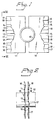
- Figure 1 shows a surface enlarging element according to the invention in which the depth of the slits decreases towards the short sides of the element.
- the slides are thus deeper in the mid-region of the longitudinal direction of the element.
- This variation in depth of the slits, combined with tongues 17 of equal width, has proved to offer a particularly uniform temperature distribution during operation for the peripheral area of the surface enlarging element, which in turn entails negligible thermal deformation.
- the tongues 17 may be deformed to an angled cross section, neighbouring tongues thus being bent in opposite directions.
- the element 11 may be of the same material as the tube 18, e.g. steel. It is important that the material of the element has high thermal conductivity since this will improve its efficiency. If steel is used, therefore, a steel with low carbon content is preferably selected.
- the slits 14 - 16 have a width of 6 mm
- the central slit 15 has a depth of 25 mm
- the outer slits have a depth of 15 mm.
- the two central tongues have a width of 19 mm and the two outer tongues have a width of 22 mm.
- the length of the element 11 is 100 mm and its width is 55 mm.
- the recess has a radius of about 23,5 mm and a depth of about 17,5 mm.
- the distance between the centres of the tubes in the longitudinal direction of the element 11 is about 108 mm, whereas the distance between the centres of the tubes in the transverse direction of the element is about 125 mm in one example of a heat exchanger.
- Each piece of metal 11 has a width B appropriate for the installation, a suitable width being approximately twice the outer diameter of the tube, and a depth of approximately 0.5B.
- a substantially circular recess In one long side of the piece of metal, in its mid-region, is a substantially circular recess.
- the radius of this recess is somewhat greater, e.g. 1 mm greater, than the radius of the tube, and its depth is less than the radius.
- the edge of the recess thus extends through an angle of somewhat less than 180°.
- a gap is thus obtained between two pieces of metal 11 welded to the tube in the same plane. This facilitates welding and also permits a certain amount of gas to flow transverse to the plane of the metal pieces.
- the difference in radius ensures a satisfactory, homogeneous welding joint if resistance welding is performed under pressure.
- the quality of the weld can be further improved if the surface of the tube and/or the attachment edge of the metal piece is coarse ground so that the grinding scores allow gas to be drawn off during the welding operation.
Landscapes
- Physics & Mathematics (AREA)
- Engineering & Computer Science (AREA)
- Geometry (AREA)
- Thermal Sciences (AREA)
- Mechanical Engineering (AREA)
- General Engineering & Computer Science (AREA)
- Heat-Exchange Devices With Radiators And Conduit Assemblies (AREA)
- Details Of Heat-Exchange And Heat-Transfer (AREA)
Claims (8)
- Oberflächenvergrößerndes Element für Wärmeübertragerrohre, welches ein im wesentliches viereckiges Teil aus einem Metallblech (11) aufweist, welches im Mittelbereich einer Längsseite mit einer im wesentlichen halbkreisförmigen Ausnehmung versehen ist, welche sich über einen Winkel von weniger als 180° hinwegerstreckt und derart ausgelegt ist, daß sie an dem Rohr anschweißbar ist, dadurch gekennzeichnet, daß das Teil aus Metallblech mit Schlitzen (14, 15, 16) versehen ist, welche sich von der anderen Längsseite des Metallteils ausgehen und im allgemeinen parallel zu den kurzen Seiten des Teils aus Metallblech (11) verlaufen, und daß die Länge der Schlitze (14, 15, 16) ausgehend von der Mitte des Metallteils in Richtung zu seinen kurzen Seiten abnimmt.
- Oberflächenvergrößerndes Element nach Anspruch 1, dadurch gekennzeichnet, daß die Länge des längsten Schlitzes (15) der Hälfte der Breite des Elements entspricht.
- Oberflächenvergrößerndes Element nach Anspruch 1 oder 2, dadurch gekennzeichnet, daß die Zungen (17), welche in dem Element durch die Schlitze (14, 15, 16) gebildet werden, ausgehend von der Mittelebene des Elements verformt sind.
- Oberflächenvergrößerndes Element nach einem der Ansprüche 1 bis 3, dadurch gekennzeichnet, daß die Zungen (17), die von den Schlitzen gebildet werden, eine im wesentlichen gleiche Breite haben.
- Wärmeübertragerrohr, welches mit oberflächenvergrößernden Elementen nach einem der Ansprüche 1 bis 4 versehen ist, dadurch gekennzeichnet, daß die oberflächenvergrößernden Elemente mittels Widerstandsschweißen an dem Rohr angeschweißt sind.
- Oberflächenvergrößerndes Element nach einem der Asprüche 1 bis 5, dadurch gekennzeichnet, dass der Radius der Ausnehmung geringfügig größer als der Radius des Rohrs ist, an welchem das Element mittels Widerstandsschweißen anzubringen ist.
- Wärmeübertragerrohr nach Anspruch 5, dadurch gekennzeichnet, daß die Oberfläche einer Schweißstelle am Rohr oder am oberflächenvergrößernden Element mit Kerben versehen ist, welche ein Abziehen des Gases von der Schweißstelle während des Widerstandsschweißverfahrens gestatten.
- Wärmeübertragerrohr nach Anspruch 5 oder 7, dadurch gekennzeichnet, daß die oberflächenvergrößernden Elemente an dem Rohr paarweise einander gegenüberliegend angeordnet und angeschweißt sind.
Priority Applications (1)
| Application Number | Priority Date | Filing Date | Title |
|---|---|---|---|
| AT89909450T ATE84139T1 (de) | 1988-09-13 | 1989-08-28 | Oberflaechenvergroesserungselemente fuer waermeaustauschleitungen. |
Applications Claiming Priority (2)
| Application Number | Priority Date | Filing Date | Title |
|---|---|---|---|
| SE8803215 | 1988-09-13 | ||
| SE8803215A SE8803215D0 (sv) | 1988-09-13 | 1988-09-13 | Ytforstoringselement for vermevexlartub |
Publications (2)
| Publication Number | Publication Date |
|---|---|
| EP0434703A1 EP0434703A1 (de) | 1991-07-03 |
| EP0434703B1 true EP0434703B1 (de) | 1992-12-30 |
Family
ID=20373307
Family Applications (1)
| Application Number | Title | Priority Date | Filing Date |
|---|---|---|---|
| EP89909450A Expired - Lifetime EP0434703B1 (de) | 1988-09-13 | 1989-08-28 | Oberflächenvergrösserungselemente für wärmeaustauschleitungen |
Country Status (7)
| Country | Link |
|---|---|
| US (1) | US5046556A (de) |
| EP (1) | EP0434703B1 (de) |
| JP (1) | JP2735664B2 (de) |
| KR (1) | KR960005789B1 (de) |
| AU (1) | AU4070689A (de) |
| SE (1) | SE8803215D0 (de) |
| WO (1) | WO1990002917A1 (de) |
Families Citing this family (13)
| Publication number | Priority date | Publication date | Assignee | Title |
|---|---|---|---|---|
| US5240070A (en) * | 1992-08-10 | 1993-08-31 | Fintube Limited Partnership | Enhanced serrated fin for finned tube |
| ES2101285T3 (es) * | 1993-12-14 | 1997-07-01 | Aalborg Ind As | Intercambiador de calor con cuerpo en forma tubular. |
| JP3292077B2 (ja) * | 1997-01-30 | 2002-06-17 | 株式会社日立製作所 | 熱交換器及び空気調和機 |
| US6009936A (en) * | 1997-04-17 | 2000-01-04 | Sanyo Electric Co., Ltd. | Heat exchanger |
| AU2003269188A1 (en) * | 2003-09-19 | 2005-04-11 | Ti Group Automotive Systems Limited | Heat exchanger cooling fin |
| KR100800770B1 (ko) * | 2006-09-07 | 2008-02-01 | 삼성전자주식회사 | 슬라이딩형 휴대용 단말기 |
| US20110308228A1 (en) * | 2010-06-18 | 2011-12-22 | General Electric Company | Fin and Tube Heat Exchanger |
| FR2978236B1 (fr) * | 2011-07-21 | 2015-08-21 | Valeo Systemes Thermiques | Echangeur thermique, tube plat et plaque correspondants |
| DE102014108209A1 (de) * | 2014-06-11 | 2015-12-17 | GEA Luftkühler GmbH | Wärmetauscher |
| CN104110989A (zh) * | 2014-06-25 | 2014-10-22 | 上海理工大学 | H型平齿翅片管及h型平齿翅片管换热管束 |
| CN106595368A (zh) * | 2016-11-29 | 2017-04-26 | 国电南京自动化股份有限公司 | 一种翅片管换热器 |
| US11774187B2 (en) * | 2018-04-19 | 2023-10-03 | Kyungdong Navien Co., Ltd. | Heat transfer fin of fin-tube type heat exchanger |
| US10859208B2 (en) * | 2018-05-31 | 2020-12-08 | Savannah River Nuclear Solutions, Llc | Heat transfer unit for prefabricated vessel |
Family Cites Families (12)
| Publication number | Priority date | Publication date | Assignee | Title |
|---|---|---|---|---|
| US2402262A (en) * | 1943-08-30 | 1946-06-18 | American Coils Co | Heat exchange fin |
| GB590715A (en) * | 1945-02-19 | 1947-07-25 | Leopold Friedman | Improvements in and relating to heat exchangers |
| FR981567A (fr) * | 1946-04-23 | 1951-05-28 | Vitkovicke Zelezarny Narodni P | Tubes à ailettes |
| CH288848A (de) * | 1949-09-12 | 1953-02-15 | Kablitz Richard | Röhrenwärmeaustauscher mit Rippenrohren und Stahlrohrseele. |
| GB902011A (en) * | 1958-03-06 | 1962-07-25 | Green & Son Ltd | Improvements in or relating to tubular heat exchangers |
| US3363682A (en) * | 1964-07-09 | 1968-01-16 | Int Combustion Holdings Ltd | Heat exchangers having vortex producing vanes |
| CH414705A (de) * | 1964-10-15 | 1966-06-15 | Bbc Brown Boveri & Cie | Wärmeaustauschelement |
| FR2131828A3 (en) * | 1971-03-29 | 1972-11-17 | Air Ind | Heat exchanger - with parallel multi-gilled tubes giving enhanced transfer of heat |
| DE2628866A1 (de) * | 1976-06-26 | 1978-01-05 | Schoell Guenter | Rippenrohr-waermeaustauschelement |
| HU183314B (en) * | 1981-02-06 | 1984-04-28 | Laszlo Szuecs | Ribbed heat exchanger and method for producing same |
| AT371592B (de) * | 1982-02-25 | 1983-07-11 | Waagner Biro Ag | Rippenrohrwaermetauscher, insbesondere dampferzeuger nach dem naturumlaufsystem |
| JPS59112196A (ja) * | 1982-12-18 | 1984-06-28 | Daikin Ind Ltd | フイン付熱交換器 |
-
1988
- 1988-09-13 SE SE8803215A patent/SE8803215D0/xx unknown
-
1989
- 1989-08-28 AU AU40706/89A patent/AU4070689A/en not_active Abandoned
- 1989-08-28 US US07/634,119 patent/US5046556A/en not_active Expired - Lifetime
- 1989-08-28 KR KR1019900700989A patent/KR960005789B1/ko not_active Expired - Fee Related
- 1989-08-28 JP JP1508894A patent/JP2735664B2/ja not_active Expired - Fee Related
- 1989-08-28 EP EP89909450A patent/EP0434703B1/de not_active Expired - Lifetime
- 1989-08-28 WO PCT/SE1989/000448 patent/WO1990002917A1/en not_active Ceased
Also Published As
| Publication number | Publication date |
|---|---|
| AU4070689A (en) | 1990-04-02 |
| JPH04500717A (ja) | 1992-02-06 |
| EP0434703A1 (de) | 1991-07-03 |
| KR960005789B1 (ko) | 1996-05-01 |
| US5046556A (en) | 1991-09-10 |
| WO1990002917A1 (en) | 1990-03-22 |
| SE8803215D0 (sv) | 1988-09-13 |
| KR900702317A (ko) | 1990-12-06 |
| JP2735664B2 (ja) | 1998-04-02 |
Similar Documents
| Publication | Publication Date | Title |
|---|---|---|
| US5046556A (en) | Surface enlarging elements for heat-exchanger tubes | |
| EP0094954B1 (de) | Wärmeaustauschplatte | |
| SU1314963A3 (ru) | Трубчато-пластинчатый теплообменник | |
| US4344480A (en) | Support for heat exchange tubes | |
| CA1079263A (en) | Heat exchanger | |
| GB1566619A (en) | Heat exchange element | |
| EP0030012B1 (de) | Verfahren zur Verbesserung des Wärmeübertragungs-Koeffizienten, Verfahren zur Herstellung eines Rohrbündels und Vorrichtung mit einer Vielzahl von parallelen Rohren | |
| EP0162828A2 (de) | Wärmetauscher | |
| EP0018388B1 (de) | Einrichtung eines plattenartigen wärmetauschers | |
| GB2049146A (en) | Finned tube for heat exchangers | |
| US3330336A (en) | Heat exchanger tubes with longitudinal ribs | |
| CA1118763A (en) | Heat exchanger | |
| GB1592125A (en) | Heat exchanger for liquid heaters | |
| DE69900710T2 (de) | Wärmetauschereinheit und ihre Verwendung | |
| CN214371969U (zh) | 一种间隔支撑件及其盘管热交换器 | |
| JPH0610584B2 (ja) | 熱交換器 | |
| JP2888313B2 (ja) | 積層式熱交換器 | |
| IE52252B1 (en) | Space heater | |
| US5050670A (en) | Four piece elbow for a multi-tube heat exchanger | |
| GB2032091A (en) | Heat exchangers | |
| EP0122667A1 (de) | Wärmetauscher und Zentralheizungskessel mit einem solchen Wärmetauscher | |
| JPH0749189A (ja) | 熱交換器 | |
| JPS6183882A (ja) | プレ−ト式熱交換器 | |
| JPH07117349B2 (ja) | 熱交換器 | |
| SU1539500A1 (ru) | Элемент пластинчатого теплообменника |
Legal Events
| Date | Code | Title | Description |
|---|---|---|---|
| PUAI | Public reference made under article 153(3) epc to a published international application that has entered the european phase |
Free format text: ORIGINAL CODE: 0009012 |
|
| 17P | Request for examination filed |
Effective date: 19901114 |
|
| AK | Designated contracting states |
Kind code of ref document: A1 Designated state(s): AT BE CH DE FR GB IT LI LU NL SE |
|
| 17Q | First examination report despatched |
Effective date: 19910802 |
|
| GRAA | (expected) grant |
Free format text: ORIGINAL CODE: 0009210 |
|
| ITF | It: translation for a ep patent filed | ||
| AK | Designated contracting states |
Kind code of ref document: B1 Designated state(s): AT BE CH DE FR GB IT LI LU NL SE |
|
| REF | Corresponds to: |
Ref document number: 84139 Country of ref document: AT Date of ref document: 19930115 Kind code of ref document: T |
|
| REF | Corresponds to: |
Ref document number: 68904200 Country of ref document: DE Date of ref document: 19930211 |
|
| ET | Fr: translation filed | ||
| PG25 | Lapsed in a contracting state [announced via postgrant information from national office to epo] |
Ref country code: LU Free format text: LAPSE BECAUSE OF NON-PAYMENT OF DUE FEES Effective date: 19930831 |
|
| PLBE | No opposition filed within time limit |
Free format text: ORIGINAL CODE: 0009261 |
|
| STAA | Information on the status of an ep patent application or granted ep patent |
Free format text: STATUS: NO OPPOSITION FILED WITHIN TIME LIMIT |
|
| 26N | No opposition filed | ||
| EAL | Se: european patent in force in sweden |
Ref document number: 89909450.2 |
|
| REG | Reference to a national code |
Ref country code: GB Ref legal event code: IF02 |
|
| PGFP | Annual fee paid to national office [announced via postgrant information from national office to epo] |
Ref country code: GB Payment date: 20050812 Year of fee payment: 17 |
|
| PGFP | Annual fee paid to national office [announced via postgrant information from national office to epo] |
Ref country code: SE Payment date: 20050823 Year of fee payment: 17 |
|
| PGFP | Annual fee paid to national office [announced via postgrant information from national office to epo] |
Ref country code: BE Payment date: 20050829 Year of fee payment: 17 Ref country code: CH Payment date: 20050829 Year of fee payment: 17 |
|
| PGFP | Annual fee paid to national office [announced via postgrant information from national office to epo] |
Ref country code: AT Payment date: 20050831 Year of fee payment: 17 Ref country code: FR Payment date: 20050831 Year of fee payment: 17 Ref country code: NL Payment date: 20050831 Year of fee payment: 17 |
|
| PGFP | Annual fee paid to national office [announced via postgrant information from national office to epo] |
Ref country code: DE Payment date: 20051026 Year of fee payment: 17 |
|
| PG25 | Lapsed in a contracting state [announced via postgrant information from national office to epo] |
Ref country code: AT Free format text: LAPSE BECAUSE OF NON-PAYMENT OF DUE FEES Effective date: 20060828 |
|
| PG25 | Lapsed in a contracting state [announced via postgrant information from national office to epo] |
Ref country code: SE Free format text: LAPSE BECAUSE OF NON-PAYMENT OF DUE FEES Effective date: 20060829 |
|
| PG25 | Lapsed in a contracting state [announced via postgrant information from national office to epo] |
Ref country code: CH Free format text: LAPSE BECAUSE OF NON-PAYMENT OF DUE FEES Effective date: 20060831 Ref country code: BE Free format text: LAPSE BECAUSE OF NON-PAYMENT OF DUE FEES Effective date: 20060831 Ref country code: LI Free format text: LAPSE BECAUSE OF NON-PAYMENT OF DUE FEES Effective date: 20060831 |
|
| PGFP | Annual fee paid to national office [announced via postgrant information from national office to epo] |
Ref country code: IT Payment date: 20060831 Year of fee payment: 18 |
|
| PG25 | Lapsed in a contracting state [announced via postgrant information from national office to epo] |
Ref country code: NL Free format text: LAPSE BECAUSE OF NON-PAYMENT OF DUE FEES Effective date: 20070301 Ref country code: DE Free format text: LAPSE BECAUSE OF NON-PAYMENT OF DUE FEES Effective date: 20070301 |
|
| REG | Reference to a national code |
Ref country code: CH Ref legal event code: PL |
|
| EUG | Se: european patent has lapsed | ||
| GBPC | Gb: european patent ceased through non-payment of renewal fee |
Effective date: 20060828 |
|
| NLV4 | Nl: lapsed or anulled due to non-payment of the annual fee |
Effective date: 20070301 |
|
| REG | Reference to a national code |
Ref country code: FR Ref legal event code: ST Effective date: 20070430 |
|
| PG25 | Lapsed in a contracting state [announced via postgrant information from national office to epo] |
Ref country code: GB Free format text: LAPSE BECAUSE OF NON-PAYMENT OF DUE FEES Effective date: 20060828 |
|
| BERE | Be: lapsed |
Owner name: *GADELIUS SUNROD A.B. Effective date: 20060831 |
|
| PG25 | Lapsed in a contracting state [announced via postgrant information from national office to epo] |
Ref country code: FR Free format text: LAPSE BECAUSE OF NON-PAYMENT OF DUE FEES Effective date: 20060831 |
|
| PG25 | Lapsed in a contracting state [announced via postgrant information from national office to epo] |
Ref country code: IT Free format text: LAPSE BECAUSE OF NON-PAYMENT OF DUE FEES Effective date: 20070828 |