EP0434892A2 - Verfahren zum Prägen von Textilien - Google Patents
Verfahren zum Prägen von Textilien Download PDFInfo
- Publication number
- EP0434892A2 EP0434892A2 EP90109994A EP90109994A EP0434892A2 EP 0434892 A2 EP0434892 A2 EP 0434892A2 EP 90109994 A EP90109994 A EP 90109994A EP 90109994 A EP90109994 A EP 90109994A EP 0434892 A2 EP0434892 A2 EP 0434892A2
- Authority
- EP
- European Patent Office
- Prior art keywords
- embossing
- foam
- foam sheet
- film
- textile material
- Prior art date
- Legal status (The legal status is an assumption and is not a legal conclusion. Google has not performed a legal analysis and makes no representation as to the accuracy of the status listed.)
- Granted
Links
Images
Classifications
-
- D—TEXTILES; PAPER
- D06—TREATMENT OF TEXTILES OR THE LIKE; LAUNDERING; FLEXIBLE MATERIALS NOT OTHERWISE PROVIDED FOR
- D06C—FINISHING, DRESSING, TENTERING OR STRETCHING TEXTILE FABRICS
- D06C23/00—Making patterns or designs on fabrics
- D06C23/04—Making patterns or designs on fabrics by shrinking, embossing, moiréing, or crêping
-
- B—PERFORMING OPERATIONS; TRANSPORTING
- B32—LAYERED PRODUCTS
- B32B—LAYERED PRODUCTS, i.e. PRODUCTS BUILT-UP OF STRATA OF FLAT OR NON-FLAT, e.g. CELLULAR OR HONEYCOMB, FORM
- B32B2305/00—Condition, form or state of the layers or laminate
- B32B2305/02—Cellular or porous
- B32B2305/022—Foam
-
- B—PERFORMING OPERATIONS; TRANSPORTING
- B32—LAYERED PRODUCTS
- B32B—LAYERED PRODUCTS, i.e. PRODUCTS BUILT-UP OF STRATA OF FLAT OR NON-FLAT, e.g. CELLULAR OR HONEYCOMB, FORM
- B32B2305/00—Condition, form or state of the layers or laminate
- B32B2305/10—Fibres of continuous length
- B32B2305/18—Fabrics, textiles
Definitions
- the invention relates to a method for embossing textiles, in which adjacent layers made of a textile material and a film material are pressed between two opposing embossing surfaces and bonded together.
- the object of the present invention is to propose a method for embossing textiles, in which a substantially improved dimensional stability of the embossing is ensured compared to the known methods.
- this object is achieved in that a foam sheet is used as the sheet material and the foam sheet is compressed differently in different surface areas to form an embossed pattern.
- the foam sheet is embossed by permanent compression of the foam material in accordance with the embossing pattern, whereby the connection of the embossed textile material with the embossed foam material results in significantly improved dimensional stability, particularly when cleaning Washing, ironing and drying are maintained.
- the embossing takes place on the condition that the two embossing surfaces are designed as flat surfaces and that recesses corresponding to the embossing pattern are provided in one of the two surfaces.
- the recesses can be provided so deep that the foam film is not or only slightly compressed in the region of the recess.
- the foam sheet can be compressed outside of the recesses until or almost until the foam structure is lifted.
- the textile material remains relatively flexible in the area of the embossing, since the structure of the foam film has only been retained in the above areas of the embossing.
- the embossed area is surrounded by a closed edge in which the foam material or is compressed almost to the point where the foam structure is eliminated. Since a particularly firm connection between the textile and the film material is achieved in the highly compressed areas, this ensures that the film material cannot detach from the textile material from the edge.
- a further layer made of a plastic film is arranged between the textile material layer and the foam film.
- This plastic film which melts under the influence of heat during the embossing process and causes a melt connection between the foam film and the textile material, prevents the foam film material, which melts even at low temperature, from penetrating too deeply into the textile material and, for example, impairing the appearance of the embossing up to opposite surface can reach.
- a film of low density polyethylene is preferably used as such a barrier film.
- An easily deformable polyethylene foam with a density of 24 kg / m3 is expediently used as the foam film material, the film having a thickness of approximately 2 mm in most applications.
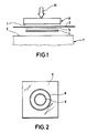
- the reference numeral 6 denotes an embossing stamp with an embossing surface 1 and the reference number 7 denotes a support with a support surface 2.
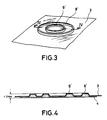
- the bearing surface 2 is a flat surface, while the surface 1 of the stamping die has the stamping pattern shown in FIG. 2 with the circular concentric grooves 8 and 9.
- a textile material layer 3 to be embossed there is a textile material layer 3 to be embossed, a foam film layer 4 and between the textile material layer 3 and the foam film layer 4 another layer made of a polyethylene film 5.
- the foam sheet layer is made of polyethylene and has a thickness of 2 mm with a material density of 24 kg / m3.
- the thickness of the film arranged between the textile material layer 3 and the foam film layer 4 is 25 ⁇ m in the present exemplary embodiment and it is high-pressure polyethylene with a low density of 0.918-0.93 gcm ⁇ 3. It has been found that it is advantageous to add films in the range from 25 to 40 ⁇ m use, but foils up to a thickness of 100 ⁇ m can also be used. Depending on the desired embossing, foam films with thicknesses and densities can also be used which deviate upwards or downwards from the values selected for the present exemplary embodiment.
- the thickness of the foam sheet can be between 1 and 3 mm. Tricotage materials or other textile materials come into consideration as the textile material to be embossed.
- Both the stamping die 6, which is preferably made of aluminum, and the base 7 are heated by devices not shown in FIG. 1.
- the embossing die 6 When embossing the textile material 3, the embossing die 6 is pressed down in the direction of the arrow 10, the heat pattern corresponding to the embossing pattern shown in FIG. 2 causing the foam sheet material to melt in the areas outside the grooves 8 and 9, melting the Foam material is compressed so far that the foam structure is almost eliminated, while the foam material in the area of the grooves 8 and 9 protrudes into the grooves, which in the present exemplary embodiment are chosen so deep that the foam material is hardly compressed in the area of the grooves.
- the action of heat causes the film 5 to melt, so that when the melted plastic material penetrates the textile material, a melt connection is produced between the textile material and the foam material.
- the film 5 used ensures that the foam material, which melts at a lower temperature than the material of the film 5, does not penetrate too deep into the textile material and in particular does not penetrate as far as the surface of the textile material layer 3 facing the embossing die 6 the textile material penetrates.
- the foam sheet material melts at least on the surface, so that there is a melt connection with the textile material in these areas as well.
- the melting temperature of the foam material was 107.6 ° C and that of the film 5 110.1 o C.
- the pressing pressure during embossing is preferably in a range between 5 and 8 bar, with the temperature on the surfaces 1 and preferably C and the stamping time in the range 2 is in the range between 140 and 180 o 3-5 seconds.
- the grooves 8 and 9 of the embossing stamp correspond to protruding embossing areas in the form of two concentric circles.
- 4 shows that the foam material is only slightly compressed in the area of the grooves or the protruding rings and has an initial thickness of approximately 2 mm. In contrast, the material in the areas outside the grooves is compressed to such an extent that the foam structure is almost eliminated.
- the film 5 is not shown in FIG. 4, since it largely melts during the embossing process and connects to the surface of the foam film or the molten material penetrates into the textile material.
- embossings are also conceivable in which the foam sheet material is compressed in the entire embossing area, but the maximum For example, compression only takes place up to a reduction in the film thickness to a third.
- stamping rollers could also be used.
- the described embossing process for textiles can also be used for embossing leather, including artificial leather, and in particular for embossing thin leather.
Landscapes
- Engineering & Computer Science (AREA)
- Textile Engineering (AREA)
- Treatment Of Fiber Materials (AREA)
- Shaping Of Tube Ends By Bending Or Straightening (AREA)
- Treatments For Attaching Organic Compounds To Fibrous Goods (AREA)
- Laminated Bodies (AREA)
Abstract
Description
- Die Erfindung betrifft ein Verfahren zum Prägen von Textilien, bei dem aneinander anliegende Lagen aus einem Textilmaterial und aus einem Folienmaterial zwischen zwei einander gegenüberliegenden Prägeflächen gepreßt und miteinander verbunden werden.
- Bei derartigen bekannten Verfahren zum Prägen von Textilien sind die einander gegenüberliegenden Flächen, zwischen denen das Textilmaterial zusammen mit dem Folienmaterial zum Prägen und Verbinden gepreßt wird, mit einer positiven und einer der positiven entsprechenden negativen Prägeform versehen. Durch die beim Prägen permanent verformte Folie wird zwar der Prägung eine gewisse Formbeständigkeit verliehen, diese ist jedoch unter den für Textilien typischen Beanspruchungen beim Waschen, Bügeln und Trocknen nicht ausreichend. Textilerzeugnisse, die nach den bisher bekannten Verfahren hergestellte Prägungen aufweisen, sind daher meist schon nach einmaliger Reinigung oder Wäsche unansehnlich, indem die Prägung nur noch andeutungsweise vorhanden und das eingeprägte Motiv nicht mehr oder nur noch teilweise erkennbar ist.
- Der vorliegenden Erfindung liegt die Aufgabe zugrunde, ein Verfahren zum Prägen von Textilien vorzuschlagen, bei dem gegenüber den bekannten Verfahren eine wesentlich verbesserte Formbeständigkeit der Prägung gewährleistet ist.
- Erfindungsgemäß wird diese Aufgabe dadurch gelöst, daß als Folienmaterial eine Schaumstoffolie verwendet und die Schaumstoffolie zur Bildung eines eingeprägten Musters in verschiedenen Flächenbereichen unterschiedlich verdichtet wird.
- Durch diese erfindungsgemäße Lösung, bei der Prägeflächen mit negativen Prägemustern verwendet werden, erfolgt eine Prägung der Schaumstoffolie durch permanente Verdichtung des Schaumstoffmaterials entsprechend dem Prägemuster, wobei durch die Verbindung des geprägten Textilmaterials mit dem geprägten Schaumstoffmaterial eine wesentlich verbesserte Formbeständigkeit, die insbesondere auch beim Reinigen, Waschen, Bügeln und Trocknen erhalten bleibt, erreicht wird.
- In vorteilhafter Ausgestaltung der Erfindung erfolgt das Prägen unter der Bedingung, daß die beiden Prägeflächen als ebene Flächen ausgebildet sind und in der einen der beiden Flächen dem Prägemuster entsprechende Ausnehmungen vorgesehen sind. Dabei können die Ausnehmungen so tief vorgesehen sein, daß die Schaumstoffolie im Bereich der Ausnehmung nicht oder nur geringfügig verdichtet wird. Andererseits kann die Schaumstoffolie außerhalb der Ausnehmungen bis oder nahezu bis zur Aufhebung der Schaumstoffstruktur verdichtet sein. In diesem Fall bleibt das Textilmaterial im Bereich der Prägung verhältnismäßig flexibel, indem die Struktur der Schaumstoffolie nur in den vorstehenden Bereichen der Prägung erhalten geblieben ist.
- Zweckmäßig umgibt den geprägten Bereich ein geschlossener Rand, in dem das Schaumstoffmaterial bis oder nahezu bis zur Aufhebung der Schaumstoffstruktur verdichtet ist. Da in den hochverdichteten Bereichen eine besonders feste Verbindung zwischen dem Textil- und dem Folienmaterial erreicht wird, ist dadurch gesichert, daß es vom Rand her nicht zu einer Ablösung des Folienmaterials vom Textilmaterial kommen kann.
- In weiterer vorteilhafter Ausgestaltung der Erfindung kann vorgesehen sein, daß zwischen der Textilmateriallage und der Schaumstoffolie eine weitere Lage aus einer Kunststoffolie angeordnet wird. Durch diese Kunststoffolie, die während des Prägevorgangs unter Wärmeeinwirkung schmilzt und eine Schmelzverbindung zwischen der Schaumstoffolie und dem Textilmaterial hervorruft, wird verhindert, daß das schon bei niedriger Temperatur schmelzende Schaumstoffolienmaterial zu tief in das Textilmaterial eindringt und zum Beispiel unter Beeinträchtigung der Ansehnlichkeit der Prägung bis zur gegenüberliegenden Oberfläche gelangen kann. Als eine solche Sperrfolie wird vorzugsweise eine Folie aus Polyethylen geringer Dichte eingesetzt.
- Als Schaumstoffolienmaterial wird zweckmäßig ein leicht verformbarer Polyethylenschaum mit einer Dichte von 24 kg/m³ verwendet, wobei die Folie in den meisten Anwendungsfällen eine Dicke von ca. 2 mm aufweist.
- Weitere vorteilhafte Ausgestaltungsmöglichkeiten der Erfindung gehen aus den Unteransprüchen hervor.
- Das erfindungsgemäße Verfahren soll nun anhand eines Ausführungsbeispiels und der beiliegenden, dieses Ausführungsbespiel betreffenden Zeichnungen weiter erläutert und beschrieben werden. Es zeigen:
- Fig.1 schematisch eine Anordnung zur Ausführung des erfindungsgemäßen Prägeverfahrens,
- Fig.2 den bei der Anordnung von Fig. 1 vorgesehenen Prägestempel mit einem Prägemuster,
- Fig.3 ein nach der Anordnung von Fig. 1 geprägtes Textilmaterialstück, und
- Fig.4 das Textilmaterialstück gemäß der Fig. 3 in einer Schnittdarstellung gemäß der Schnittlinie A-A von Fig. 3.
- In der Fig. 1 ist mit dem Bezugszeichen 6 ein Prägestempel mit einer Prägefläche 1 und mit dem Bezugszeichen 7 eine Auflage mit einer Auflagefläche 2 bezeichnet. Die Auflagefläche 2 ist eine ebene Fläche, während die Fläche 1 des Prägestempels das in Fig. 2 gezeigte Prägemuster mit den kreisförmigen konzentrischen Rillen 8 und 9 aufweist. Zwischen der Fläche 1 und der Fläche 2 sind eine zu prägende Textilmateriallage 3, eine Schaumstoffolienlage 4 und zwischen der Textilmateriallage 3 und der Schaumstoffolienlage 4 eine weitere Lage aus einer Polyethylenfolie 5 angeordnet. Im vorliegenden Ausführungsbeispiel besteht die Schaumstoffolienlage aus Polyethylen und weist eine Dicke von 2 mm bei einer Materialdichte von 24 kg/m³ auf. Die Dicke der zwischen der Textilmateriallage 3 und der Schaumstoffolienlage 4 angeordneten Folie beträgt im vorliegenden Ausführungsbeispiel 25 µm und es handelt sich um Hochdruck-Polyethylen mit einer geringen Dichte von 0,918-0,93 gcm⁻³. Es hat sich herausgestellt, daß es zweckmäßig ist, Folien im Bereich von 25 bis 40 µm zu verwenden, wobei aber auch Folien bis zu einer Dicke von 100 µm einsetzbar sind. Je nach erwünschter Prägung können auch Schaumstoffolien mit Dicken und Dichten verwendet werden, die von den für das vorliegende Ausführungsbeispiel gewählten Werten nach oben oder unten abweichen. Die Dicke der Schaumstoffolie kann zwischen 1 und 3 mm liegen. Als zu prägendes Textilmaterial kommen Tricotagenmaterialien oder andere textile Materialien in Betracht.
- Sowohl der vorzugsweise aus Aluminium gefertige Prägestempel 6 als auch die Unterlage 7 werden durch in der Fig. 1 nicht dargestellte Einrichtungen beheizt.
- Beim Prägen des Textilmaterials 3 wird der Prägestempel 6 in Richtung des Pfeils 10 nach unten gedrückt, wobei es unter der Wärmeeinwirkung entsprechend dem in der Fig. 2 gezeigten Prägemuster dazu kommt, daß das Schaumstoffolienmaterial in den Bereichen außerhalb der Rillen 8 und 9 unter Schmelzen des Schaumstoffmaterials soweit verdichtet wird, daß die Schaumstoffstruktur nahezu aufgehoben ist, während das Schaumstoffmaterial im Bereich der Rillen 8 und 9 in die Rillen hineinsteht, die im vorliegenden Ausführungsbeispiel so tief gewählt sind, daß das Schaumstoffmaterial im Bereich der Rillen kaum verdichtet wird. Durch die Wärmeeinwirkung kommt es zum Schmelzen der Folie 5, so daß unter Eindringen des geschmolzenen Kunststoffmaterials in das Textilmaterial eine Schmelzverbindung zwischen dem Textilmaterial und dem Schaumstoffmaterial hergestellt wird. Die verwendete Folie 5 sorgt dafür, daß das Schaumstoffmaterial, das bei niedrigerer Temperatur als das Material der Folie 5 schmilzt, nicht zu tief in das Textilmaterial eindringt und insbesondere nicht bis zur dem Prägestempel 6 zugewandten Oberfläche der Textilmateriallage 3 durch das Textilmaterial hindurchdringt. In den Bereichen der Rillen 8 und 9 schmilzt das Schaumstoffolienmaterial wenigstens an der Oberfläche, so daß es auch in diesen Bereichen zur einer Schmelzverbindung mit dem Textilmaterial kommt. Im vorliegenden Fall betrug die Schmelztemperatur des Schaumstoffmaterials 107,6°C und die der Folie 5 110,1oC.
- Der Preßdruck beim Prägen liegt vorzugsweise in einem Bereich zwischen 5 und 8 bar, wobei die Temperatur auf den Flächen 1 und 2 vorzugsweise im Bereich zwischen 140 und 180oC und die Prägedauer im Bereich von 3 bis 5 Sekunden liegt.
- In der Fig. 3, die ein entsprechend der Anordnung gemäß der Fig. 1 und 2 geprägtes Textilmaterialstück zeigt, sind mit 8′ und 9′ den Rillen 8 und 9 des Prägestempels entsprechende vorstehende Prägebereiche in Form zweier konzentrischer Kreise bezeichnet. Aus der Fig. 4 geht hervor, daß das Schaumstoffmaterial im Bereich der Rillen bzw. der vorstehenden Ringe nur wenig verdichtet ist und die Ausgangsdicke von etwa 2 mm aufweist. Dagegen ist in den Bereichen außerhalb der Rillen das Material soweit verdichtet, daß die Schaumstoffstruktur nahezu aufgehoben ist. Die Folie 5 ist in der Fig. 4 nicht mit eingezeichnet, da sie beim Prägevorgang weitgehend schmilzt und sich mit der Oberfläche der Schaumstoffolie verbindet bzw. das geschmolzene Material in das Textilmaterial eindringt.
- Anstelle der in den Fig. 3 und 4 dargestellten Prägung mit extrem wenig und extrem stark verdichteten Teilen der Schaumstoffolie sind auch Prägungen denkbar, bei denen im gesamten Prägebereich eine Verdichtung des Schaumstoffolienmaterials erfolgt, aber die maximale Verdichtung zum Beispiel nur bis zu einer Verringerung der Foliendicke auf ein Drittel erfolgt.
- Anstelle der verwendeten plattenförmigen Prägewerkzeuge könnten auch Prägewalzen eingesetzt werden.
- Mit dem erfindungsgemäßen Verfahren lassen sich Textilien mit Prägungen herstellen, wobei die Prägungen unter den für Textilien typischen Beanspruchungen beim Waschen, Bügeln und Trocknen ihre Formbeständigkeit bewahren.
- Das beschriebene Prägeverfahren für Textilien kann auch zum Prägen von Leder, einschließlich künstlichem Leder, und insbesondere zum Prägen von dünnem Leder eingesetzt werden.
Claims (17)
Applications Claiming Priority (2)
| Application Number | Priority Date | Filing Date | Title |
|---|---|---|---|
| DE3938966A DE3938966A1 (de) | 1989-11-24 | 1989-11-24 | Verfahren zum praegen von textilien |
| DE3938966 | 1989-11-24 |
Publications (3)
| Publication Number | Publication Date |
|---|---|
| EP0434892A2 true EP0434892A2 (de) | 1991-07-03 |
| EP0434892A3 EP0434892A3 (en) | 1992-05-20 |
| EP0434892B1 EP0434892B1 (de) | 1996-03-27 |
Family
ID=6394132
Family Applications (1)
| Application Number | Title | Priority Date | Filing Date |
|---|---|---|---|
| EP90109994A Expired - Lifetime EP0434892B1 (de) | 1989-11-24 | 1990-05-25 | Verfahren zum Prägen von Textilien |
Country Status (4)
| Country | Link |
|---|---|
| EP (1) | EP0434892B1 (de) |
| AT (1) | ATE136072T1 (de) |
| DE (2) | DE3938966A1 (de) |
| RU (1) | RU2015228C1 (de) |
Cited By (1)
| Publication number | Priority date | Publication date | Assignee | Title |
|---|---|---|---|---|
| FR2745306A1 (fr) * | 1996-02-28 | 1997-08-29 | Loris Azzaro | Procede pour realiser un motif ornemental sur une etoffe |
Families Citing this family (5)
| Publication number | Priority date | Publication date | Assignee | Title |
|---|---|---|---|---|
| DE4116040C2 (de) * | 1989-11-24 | 2003-01-30 | Weiss Gisbert Gmbh | Textilverbundmaterial und Verfahren zu seiner Herstellung |
| DE4201766A1 (de) * | 1992-01-23 | 1993-07-29 | Tpm Textilpraegemaschinen Gmbh | Verfahren zum praegen und bedrucken von textilmaterialien |
| US6193914B1 (en) | 1995-11-30 | 2001-02-27 | Ubertech Texas, Inc. | Molding thermosetting polymers onto substrates |
| US6241930B1 (en) | 1995-11-30 | 2001-06-05 | Ubertech Texas, Inc. | Method of constructing a garment with a graphical design thereon |
| RU2178032C2 (ru) * | 1999-12-30 | 2002-01-10 | Московский государственный университет сервиса | Способ придания объемных эффектов трикотажным изделиям |
Family Cites Families (5)
| Publication number | Priority date | Publication date | Assignee | Title |
|---|---|---|---|---|
| US3471354A (en) * | 1964-08-19 | 1969-10-07 | Rohm & Haas | Embossing apparatus |
| DE1811422A1 (de) * | 1968-11-28 | 1970-06-18 | Messerschmitt Boelkow Blohm | Summen-Differentialschutzeinrichtung,vorzugsweise fuer Flugzeugbordnetze |
| CH300169A4 (de) * | 1969-02-27 | 1973-02-28 | ||
| FR2437935A1 (fr) * | 1978-10-05 | 1980-04-30 | Bouhaniche Marc | Piece composite de materiaux souples et son procede de fabrication |
| FR2614577B1 (fr) * | 1987-04-28 | 1989-10-06 | Gravurex Sarl | Procede de realisation d'un motif en creux et/ou relief sur un materiau souple notamment destine a la confection de vetements; materiau multicouche utilisable pour la mise en oeuvre du procede et produit notamment destine a la confection, realise au moyen de ce materiau multicouche |
-
1989
- 1989-11-24 DE DE3938966A patent/DE3938966A1/de active Granted
-
1990
- 1990-05-25 EP EP90109994A patent/EP0434892B1/de not_active Expired - Lifetime
- 1990-05-25 AT AT90109994T patent/ATE136072T1/de not_active IP Right Cessation
- 1990-05-25 DE DE59010244T patent/DE59010244D1/de not_active Expired - Fee Related
- 1990-11-23 RU SU904831795A patent/RU2015228C1/ru active
Cited By (1)
| Publication number | Priority date | Publication date | Assignee | Title |
|---|---|---|---|---|
| FR2745306A1 (fr) * | 1996-02-28 | 1997-08-29 | Loris Azzaro | Procede pour realiser un motif ornemental sur une etoffe |
Also Published As
| Publication number | Publication date |
|---|---|
| DE59010244D1 (de) | 1996-05-02 |
| DE3938966A1 (de) | 1991-05-29 |
| EP0434892A3 (en) | 1992-05-20 |
| EP0434892B1 (de) | 1996-03-27 |
| DE3938966C2 (de) | 1992-04-09 |
| ATE136072T1 (de) | 1996-04-15 |
| RU2015228C1 (ru) | 1994-06-30 |
Similar Documents
| Publication | Publication Date | Title |
|---|---|---|
| DE2835665C2 (de) | Verfahren zum Herstellen einer Auskleidung aus einer Verbundschichtplatte | |
| DE69433547T2 (de) | Gemustertes schleifmittel und verfahren | |
| DE3801059C2 (de) | Reparaturflicken für Fahrzeugkarosserien | |
| DE3501354A1 (de) | Innenverkleidungsteil fuer kraftfahrzeuge und vorrichtungen zu seiner herstellu ng | |
| DE4419908C2 (de) | Verfahren zum Herstellen eines kaschierten Formteiles | |
| DE2511597A1 (de) | Verfahren zum waermeverbinden von thermoplastischen materialien | |
| DE3537997C2 (de) | ||
| EP0434892B1 (de) | Verfahren zum Prägen von Textilien | |
| DE68925108T2 (de) | Verfahren und Form zum Herstellen eines mehrschichtigen geformten Gegenstandes | |
| DE69510805T2 (de) | Verfahren zum herstellen einer platte beschichtet mit einer verblendungsfläche, insbesondere textil | |
| DE3439474A1 (de) | Tuer- oder fensterprofil aus kunststoff und werkzeug zum herstellen des profils | |
| EP0353413B1 (de) | Faltenbalg | |
| DE3621054A1 (de) | Verfahren und vorrichtung zum verbinden flexibler materialien | |
| DE3220768C2 (de) | Verfahren zum Herstellen von mit einer strukturierten Dekorschicht versehenen Formteilen aus Faservliesen | |
| EP0630320B1 (de) | Klebstoff zur flächigen, insbesondere punktförmigen verbindung von zwei materialschichten | |
| DE3620192C2 (de) | ||
| DE2353157A1 (de) | Verfahren zum bilden einer imitierten naehnaht auf einem grundblatt aus thermoplastischem werkstoff | |
| DE4103389A1 (de) | Verfahren zum herstellen von werkstuecken zur oertlichen versteifung von gegenstaenden aus schmiegsamem material, insbesondere innenkappen fuer schuhe | |
| DE1504385A1 (de) | Verfahren zur Herstellung einer Faserschichtung | |
| DE1504742A1 (de) | Verfahren und Vorrichtung zum Verbinden von duennen Metallfolien mit Hartschaum | |
| DE69617067T2 (de) | Verfahren zum Herstellen eines mehrschichtigen Gegenstandes | |
| DE2541667A1 (de) | Verfahren zur herstellung gedruckter schaltungsplatinen | |
| DE2835822B2 (de) | Absorptionsfähiger Schichtstoff und Verfahren | |
| DE2945939A1 (de) | Verfahren zum erhalten verstaerkter zonen auf gewebe und damit erhaltene artikel, insbesondere miederwaren und bekleidung | |
| DE1259430B (de) | Verfahren zur Herstellung gedruckter Schaltungen durch Auflegen einer Metallfolie auf eine elastische Unterlage |
Legal Events
| Date | Code | Title | Description |
|---|---|---|---|
| PUAI | Public reference made under article 153(3) epc to a published international application that has entered the european phase |
Free format text: ORIGINAL CODE: 0009012 |
|
| 17P | Request for examination filed |
Effective date: 19901205 |
|
| AK | Designated contracting states |
Kind code of ref document: A2 Designated state(s): AT CH DE ES FR GB GR IT LI NL |
|
| PUAL | Search report despatched |
Free format text: ORIGINAL CODE: 0009013 |
|
| AK | Designated contracting states |
Kind code of ref document: A3 Designated state(s): AT CH DE ES FR GB GR IT LI NL |
|
| 17Q | First examination report despatched |
Effective date: 19930302 |
|
| RAP3 | Party data changed (applicant data changed or rights of an application transferred) |
Owner name: GISBERT WEISS GMBH |
|
| RAP3 | Party data changed (applicant data changed or rights of an application transferred) |
Owner name: GISBERT WEISS GMBH |
|
| GRAH | Despatch of communication of intention to grant a patent |
Free format text: ORIGINAL CODE: EPIDOS IGRA |
|
| GRAA | (expected) grant |
Free format text: ORIGINAL CODE: 0009210 |
|
| AK | Designated contracting states |
Kind code of ref document: B1 Designated state(s): AT CH DE ES FR GB GR IT LI NL |
|
| PG25 | Lapsed in a contracting state [announced via postgrant information from national office to epo] |
Ref country code: IT Free format text: LAPSE BECAUSE OF FAILURE TO SUBMIT A TRANSLATION OF THE DESCRIPTION OR TO PAY THE FEE WITHIN THE PRESCRIBED TIME-LIMIT;WARNING: LAPSES OF ITALIAN PATENTS WITH EFFECTIVE DATE BEFORE 2007 MAY HAVE OCCURRED AT ANY TIME BEFORE 2007. THE CORRECT EFFECTIVE DATE MAY BE DIFFERENT FROM THE ONE RECORDED. Effective date: 19960327 Ref country code: GR Free format text: LAPSE BECAUSE OF FAILURE TO SUBMIT A TRANSLATION OF THE DESCRIPTION OR TO PAY THE FEE WITHIN THE PRESCRIBED TIME-LIMIT Effective date: 19960327 Ref country code: ES Free format text: THE PATENT HAS BEEN ANNULLED BY A DECISION OF A NATIONAL AUTHORITY Effective date: 19960327 Ref country code: FR Effective date: 19960327 Ref country code: NL Free format text: LAPSE BECAUSE OF FAILURE TO SUBMIT A TRANSLATION OF THE DESCRIPTION OR TO PAY THE FEE WITHIN THE PRESCRIBED TIME-LIMIT Effective date: 19960327 Ref country code: GB Effective date: 19960327 |
|
| REF | Corresponds to: |
Ref document number: 136072 Country of ref document: AT Date of ref document: 19960415 Kind code of ref document: T |
|
| REF | Corresponds to: |
Ref document number: 59010244 Country of ref document: DE Date of ref document: 19960502 |
|
| PG25 | Lapsed in a contracting state [announced via postgrant information from national office to epo] |
Ref country code: AT Effective date: 19960525 |
|
| PG25 | Lapsed in a contracting state [announced via postgrant information from national office to epo] |
Ref country code: LI Effective date: 19960531 Ref country code: CH Effective date: 19960531 |
|
| EN | Fr: translation not filed | ||
| NLV1 | Nl: lapsed or annulled due to failure to fulfill the requirements of art. 29p and 29m of the patents act | ||
| GBV | Gb: ep patent (uk) treated as always having been void in accordance with gb section 77(7)/1977 [no translation filed] |
Effective date: 19960327 |
|
| PLBE | No opposition filed within time limit |
Free format text: ORIGINAL CODE: 0009261 |
|
| STAA | Information on the status of an ep patent application or granted ep patent |
Free format text: STATUS: NO OPPOSITION FILED WITHIN TIME LIMIT |
|
| 26N | No opposition filed | ||
| PGFP | Annual fee paid to national office [announced via postgrant information from national office to epo] |
Ref country code: DE Payment date: 20040629 Year of fee payment: 15 |
|
| PG25 | Lapsed in a contracting state [announced via postgrant information from national office to epo] |
Ref country code: DE Free format text: LAPSE BECAUSE OF NON-PAYMENT OF DUE FEES Effective date: 20051201 |